Institute for Materials Research, Tohoku University, Sendai 980-8577, Japan
Delft University of Technology, Kavli Institute of NanoScience, 2628 CJ Delft, The Netherlands
Spin transport through interfaces Theory of electronic transport; scattering mechanisms Magnetoelectronics; spintronics: devices exploiting spin polarized transport or integrated magnetic fields
Spin transfer torque on magnetic insulators
Abstract
Recent experimental and theoretical studies focus on spin-mediated heat currents at interfaces between normal metals and magnetic insulators. We resolve conflicting estimates for the order of magnitude of the spin transfer torque by first-principles calculations. The spin mixing conductance of the interface between silver and the insulating ferrimagnet Yttrium Iron Garnet (YIG) is dominated by its real part and of the order of 1014 , i.e. close to the value for intermetallic interface, which can be explained by a local spin model.
pacs:
72.25.Mkpacs:
72.10.-dpacs:
85.75.-d1 Introduction
It has recently been reported that the magnetism of insulators can be actuated electrically and thermally by normal metal contacts [1, 2]. The material of choice is the ferrimagnet Y3Fe5O12 (YIG), because of its extremely small magnetic damping [3, 4, 5]. The low-lying excitations of magnetic insulators are spin waves, which carry heat and angular momentum [6]. Existing experiments use Pt contacts, which by means of the inverse spin Hall effect are effective spin current detectors [7]. Slonczewski [8] reports that the thermal spin transfer torque in magnetic nanopillars [9, 10] can be much more efficient than the electrically generated spin torque in metallic structures.
The electrical and thermal injection of spin and heat currents into insulating magnets is governed by the spin transfer torque at the metalinsulator interface [11, 12], which is parameterized by the spin-mixing conductance where and are the unit matrix and the matrix of interface reflection coefficients for spin spanned by the scattering channels at the Fermi energy of the metal [13]. Crude approximations such as a Stoner model with spin-split conduction bands [11] and parameterized exchange between the itinerant metal electrons and local moments of the ferromagnet [1, 8, 12] have been used to estimate for YIG interfaces222The spin mixing conductance is governed by the reflection coefficients only and remains finite when the transmission coefficients vanish. This is not a breach of the scattering theory of transport,since the incoming and outgoing scattering states are well defined as propagating states in the metallic contacts.. Experiments and initial theoretical estimates found very small spin torques that are at odds with Slonczewski’s predictions [8].
Here we report calculations of the spin mixing conductance for the AgYIG interface based on realistic electronic structures. Silver is a promising material [14] for non-local spin current detection [15], which should be more efficient than the inverse spin Hall effect in nanostructures. We demonstrate that the calculated for the AgYIG interface is much larger than expected from the Stoner model and better described by local-moment exchange fields.
2 Free-electron model
We start with a reference structure consisting of an AgFIAg(001) junction in which the ferromagnetic insulator (FI) is modeled by a spin-split vacuum barrier, i.e., the free-electron Stoner model. The vacuum potential is chosen to be spin-split by and , whereas the barrier height is adjusted to 0.3, 1.4, 2.6 and , respectively. The barrier thickness () is chosen here such that electron transmission is negligible. Table 1 lists the corresponding of AgFIAg. Both and decrease with increasing barrier height, as expected [11].
| Barrier | / | / | Re/ | Im/ |
| 0.3 | 6.3E-5 | 5.1E-6 | 0.009 | -1.1E-1 |
| 1.4 | 3.3E-8 | 7.1E-9 | 0.003 | -7.4E-2 |
| 2.6 | 3.5E-9 | 1.3E-9 | 0.001 | -4.0E-2 |
| 2.85 | 0* | 0 | 0.001 | -5.1E-2 |
| 0.3 | 7.0E-6 | 0 | 0.15 | -0.45 |
| 1.4 | 7.4E-10 | 0 | 0.08 | -0.35 |
| 2.6 | 0 | 0 | 0.05 | -0.28 |
| 2.85 | 0 | 0 | 0.04 | -0.27 |
| * 0 means a transmission probability of less than 10-10 | ||||
3 Band structure
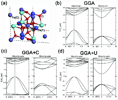
We calculate the electronic structure of YIG using the tight-binding linear-muffin-tin-orbital code in the augmented spherical wave approximation as implemented in the Stuttgart code [16, 17, 18] using the generalized gradient correction (GGA) to the local density approximation (LDA). The cubic lattice constant is chosen 1.6% smaller than the experimental one [19]. We use 136 additional empty spheres (ES) for better space filling and reduced overlap between neighboring atomic spheres. YIG is a ferrimagnetic insulator with band gap of [20, 21]. Magnetism is carried by majority and minority spin Fe atoms (tetragonal Fe(T) and octahedral Fe(O) sites in Fig.1(a), respective.) with a net magnetic moment of per formula unit [24, 23, 19, 22]. The magnetic moments are 3.95 and for majority and minority spin Fe atoms, respectively. Both Y and O atoms show small positive magnetic moments of 0.03 and 0.09, respectively, while those on the empty spheres do not exceed 0.007. The common problem of density-functional theory to predict the energy gap of insulators can be handled by an on-site Coulomb correction (LDA/GGA+U) [26, 25] or a scissor operator (LDA/GGA+C) [27]. Figure 1(b) is a plot of the band structure of GGA with a fundamental band gap of between the valence band edge of the majority-spin channel and conductance band edge of minority-spin channel. The GGA+C method can be used to increase the band gap depending on the scissor parameters C. A GGA+C band structure with a band gap of is shown in Fig. 1(c). The GGA+U method applied to the YIG band structure using the parameters from Ref. [25, 26] leads to the band structure plotted in 1(d) with the same energy gap .
| Majority-spin | Minority-spin | ||||
| VB | CB | VB | CB | ||
| GGA | 0.33 | 0.10 | 0.52 | 0.40 | 0.17 |
| GGA+Ua | 1.25 | 0.13 | 0.60 | 0.37 | 0.19 |
| GGA+Cb | 1.25 | 0.17 | 1.00 | 0.31 | 0.27 |
| GGA+Cc | 1.4 | 0.17 | 1.00 | 0.28 | 0.31 |
| GGA+Cd | 1.4 | 0.18 | 1.46 | 0.25 | 0.25 |
While a visual comparison of the band structures in Figs. 1(c) and (d) assures the equivalence of the two methods, we can assess the differences quantitatively by comparing the effective masses at the band edges as shown in Table 2. For band gaps of the effective mass at the conductance band edge of majority-spin as obtained by the GGA+U and GGA+C methods differ by up to 67%. This seems significant, but the effects on the mixing conductance, which is the quantity of our main interest here, is small, as discussed in the next section.
4 AgYIG interface
We study the spin mixing conductance in AgYIGAg with a 33 and 66 lateral supercell of fcc Ag to match a cubic YIG unit cell along the (001) and (111) directions with lattice mismatch . Interfaces can be classified according to their magnetic surface properties into three types of terminations. For the (001) texture, one cut is terminated by Y as well as majority and minority spin Fe atoms with compensated magnetic moment (“YFe-termination”). Another cut yields only majority Fe atoms at the interface (“Fe-termination”) with total magnetic moment of per lateral unit cell. The third interface covered by O atoms is obtained by removing Fe and Y atoms from the YFe-termination. The oxygen layer is separated from adjacent Fe atoms by only . Including the latter, the “O-termination” also corresponds to a net interface magnetic moment of . The interfaces for the (111) direction can be classified analogously. The “YFe-termination” cut has now a net interface magnetic moment of . The Fe-termination contains now minority-spin Fe atoms with net magnetic moment of , while the O-terminated surface has the same magnetic moment when including the shallowly buried Fe layer.
We chose a YIG film of 4 unit cell layers, because its electric conductance does not exceed / per unit cell. is therefore governed solely by the single AgYIG interface.
First, we inspect of AgYIG interfaces computed with and without scissor corrections. We find that the difference of is as small as 21% when increasing the band gap of YIG from its GGA value of to a GGA+C band gap of as shown in Table 3. We conclude that the precise band gap is a parameter that hardly affects the of the AgYIG interface.
| 0.33 | 0.65 | 0.95 | 1.4 | 1.8 | 2.1 | |
| 3.46 | 3.94 | 3.43 | 3.01 | 2.82 | 2.74 | |
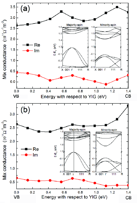
By scanning the Fermi energy of Ag (or the YIG work function), we can obtain information similar to that when varying the band gap. Scanning the Ag Fermi energy from the valence to conductance band edges for a band gap of , we obtain results equivalent to a mid-gap Fermi energy and band gaps varying from zero to , but without changing the details of the band dispersion. In Figure 2 we plot the mixing conductance of AgYIG(001) with YFe termination as a function of YIG’s work function. Here we consider two kinds of band dispersions with the same band gap of 1.4 obtained by different scissor operator implementations as shown in Table.2. We find that the mixing conductance does not depend sensitively on (i) the YIG work function or interface potential barrier as well as (ii) the band dispersion when fixing the Fermi energy of Ag in the middle of the band gap of YIG; the difference in effective mass of 46 % causes changes in of only 13%. These deviations are within the error bars due to other approximations (see below). We therefore conclude that the transport properties in the present system are sufficiently well represented by the scissor operator or on-site Coulomb correction methods for the gap problem.
Besides the band alignment discussed in the previous paragraph, two more properties are difficult to compute self-consistently for large unit cells, viz. the atomic interface configuration and the ferromagnetic proximity effect: (i): We determine the distance between AgYIG by minimizing ASA overlap while keeping the space filled. We estimate that the differences in for configurations with maximum and minimum ASA overlap is less than 30% (ii): We assess the ferromagnetic proximity effect by using the self-consistent electronic structure of Ag atom at the AgFe interface. We find that the Ag atoms closest to Fe acquire a magnetic moment of 0.025 and the effect is observable up to the 4th Ag layer. The spin mixing conductance is found to be enhanced by about 10% in this system. In the following we disregard such an effect. From various checks of these and other issues, the magnitude of a possible systematic error in the mixing conductance is estimated to be .
5 Results
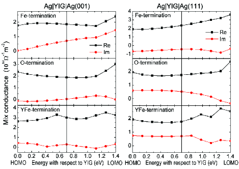
Fig. 3 summarizes our results for of AgYIG(111) and AgYIG(001) junction with different YIG interface-terminations. We find for both AgYIG(111) and AgYIG(001), with the real part dominating over the imaginary one, in stark contrast to the Stoner model (cf. Table 1). depends only weakly on exposing different YIG(111) surface cuts to Ag, which we attribute to the homogeneous distribution of magnetic atoms. The YFe termination of YIG(001) is a nearly compensated magnetic interface, but we still calculate a large spin mixing conductance. Finally, our results are two orders of magnitude larger than the experimental value found for PtYIG(111) [1]! The difference between Ag and Pt cannot account for this discrepancy: one would rather expect a larger for Pt because of its higher conduction electron density.
The difference between the Stoner model and the first-principles calculations indicate that the spin-transfer torque physics at normal metal interfaces with YIG is very different from those with transition metals. Spin-transfer is equivalent to the absorption of a spin current at an interface that is polarized transversely to the magnetization direction. Magnetism in insulators is usually described in a local moment model. The physical picture of spin transfer appropriate for metals, viz. the destructive interference of precessing spins in the ferromagnet, then obviously fails. When the spin transfer acts locally on the magnetic ions, we expect no difference for the spin absorbed by a fully ordered interface with a large net magnetic moment or a compensated one, in which the local moments point in opposite directions, as is indeed born out of our calculations.
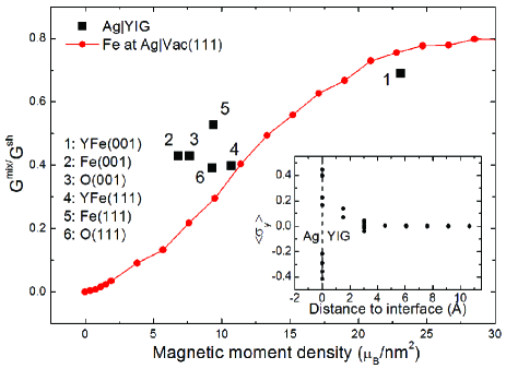
In order to test the local moment paradigm, we consider non-conducting AgVac(4L)Ag(111) junctions. We now sprinkle one vacuum interface randomly with Fe atoms. At low densities the Fe atoms are weakly coupled and form local moments. The electronic structure is generated using the Coherent Potential Approximation (CPA) for interface disorder. A lateral supercell with 100 atoms in one principle layer is used to model a magnetic impurity range from 1% to 80%. The high density limit is a monolayer of Fe atoms in the fcc structure: AgFe(1L)Vac(3L)Ag(111) with total magnetic moment of per Fe atom. So, the maximum magnetic moment density here is . The results for the mixing conductances is summarized in Fig. 4. We find that the ratio of to the (Ag) Sharvin conductances monotonically increases with the Fe density at the AgVac interface. The increase is linear at small densities and saturates around due to interactions between neighboring moments. We find that of AgYIG and AgFevacuum agrees well for corresponding Fe densities at the interface, in strong support of the local moment model.
Since the mixing conductance is dominated by the local moments at the interface, we understand that the results are relatively stable against the difficulties density functional theory has for insulators. The variation of the band gap of the insulator as well as the band alignment with respect to normal metal changes the penetration of the spin accumulation, but since only the uppermost layers contribute this is of little consequence.
| clean | 3.010 | 0.302 |
| disorder | 3.145 | 0.382 |
Table 4 shows the effect of directional disorder of magnetic moments on the mixing conductance for AgYIG(001) with YFe-termination, for which the integrated surface magnetic moment density is close to zero. Here, we use a lateral YIG supercell in which three magnetic moments are flipped to a negative value, amounting to a total surface magnetic moment of per lateral unit cell. The directional disorder of magnetic moments at the interface slightly enhances (around ), as indeed expected from the local moment picture.
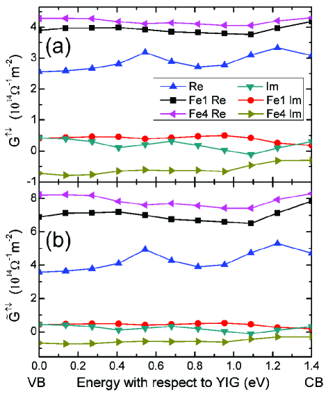
Inserting a thin ferromagnetic metallic layer between the normal metal and YIG should enhance the spin mixing conductance. In Fig. 5 (a), we show that inserting Fe atomic layers indeed increases by 40-65% up to the intermetallic AgFe value, which is close to the Ag Sharvin conductance.
In these calculation, the Ag reservoirs has been assumed to be ballistic. When the spin mixing conductance is small relative to the Sharvin conductance, this is a valid approximation, but otherwise the diffusive nature of transport may not be be neglected. Since turns out to be of the same order as we have to introduce the diffusive transport correction as introduced by Schep et al. as [28, 29]
| (1) |
The results are shown in Fig. 5(b). We observe that the ”Schep” correction enhances the spin mixing conductance by 20% for for the and about 90% for 4 nonolayers Fe insertions between Ag and YIG.
The spin transfer can be maximized by a high density of magnetic ions at the interfaces. In YIG we could not identify interface directions or cuts that are especially promising, but this could be different for other magnetic insulator, such as ferrites [8]. Slonczewski [8] uses a local moment model with a somewhat smaller exchange splitting (0.5) than found here; when defined as where is the density of the evanescent wave function in YIG at mid-gap energy disregarding its spin splitting [30], the Wigner-Seitz sphere at the lattice site , and denotes the exchange-correlation potentials for spin-up (down) electronsthe exchange splitting felt by the Ag conduction electrons at the YIG interface is up to . Since Slonzcewski focusses on the magnetization dynamics of the magnetic insulator we cannot carry out a quantitative comparison with his model here.
6 Conclusion
In conclusion, we computed the spin mixing conductance of the interface between silver and the insulating ferrimagnet Yttrium Iron Garnet (YIG). is found to be of the order of 1014 , which is much larger than expected for a Stoner model, which indicates the importance of the local magnetic exchange field at the interface. On the other hand, is not very sensitive to crystal orientation and interface cut. can be enhanced to around 40-65% of the fully metallic limit by inserting a monolayers of iron between Ag and YIG. The discrepancy between the measured and calculated mixing conductance might indicate previously unidentified interface contaminations that, when removed, would greatly improve the usefulness of magnetic insulators in spintronics.
Acknowledgements.
We would like to thank Burkard Hillebrands, Eiji Saitoh, and Ken-ichi Uchida for stimulating discussions. This work was supported by National Basic Research Program of China (973 Program) under the grant No. 2011CB921803 and NSF-China grant No. 60825404, the EC Contract ICT-257159 “MACALO” and the Dutch FOM foundation. This research was supported in part by the Project of Knowledge Innovation Program (PKIP) of Chinese Academy of Sciences, Grant No. KJCX2.YW.W10. Additional remark: After first submission of our manuscript arXiv:1103.3764, a manuscript was submitted and accepted by Physical Review Letters (Heinrich B. et al., Phys. Rev. Lett., 107 (2011) 066604) that reports a mixing conductance that is clearly enhanced compared to ref. [1], but still an order of magnitude smaller than our predictions.References
- [1] \NameKajiwara Y., Harii K., Takahashi S., Ohe J., Uchida K., Mizuguchi M., Umezawa H., Kawai H., Ando K., Takanashi K., Maekawa S. Saitoh E. \REVIEWNature 464 2010 262.
- [2] \NameUchida K., Xiao J., Adachi H., Ohe J., Takahashi S., Ieda J., Ota T., Kajiwara Y., Umezawa H., Kawai H., Bauer G. E. W., MaekawaS. Saitoh E. \REVIEWNat. Mater. 92010 894.
- [3] \Name Geller S. Gilleo M. A. \REVIEWActa Crystallogr. 10 1957239.
- [4] \NameCherepanov V., Kolokolov I. Lvov V. \REVIEWPhys. Rep.-Rev. Sec. Phys. Lett. 2291993 81.
- [5] \NameSerga A. A., Chumak A. V. Hillebrands B. \REVIEWJ. Phys. D: Appl. Phys. 43 2010 264002.
- [6] \NameSchneider T., Serga A. A., Leven B., Hillebrands B., Stamps R. L. Kostylev M. P. \REVIEWAppl. Phys. Lett. 92 2008 022505.
- [7] \NameSaitoh E., Ueda M., Miyajima H. Tatara G. \REVIEWAppl.Phys. Lett. 88 2006 182509.
- [8] \NameSlonczewski J. C. \REVIEWPhys. Rev. B 82 2010 054403.
- [9] \NameHatami M., Bauer G. E. W., Zhang Q. Kelly P. J. \REVIEWPhys. Rev. Lett. 99 2007 066603.
- [10] \NameYu H., Granville S., Yu D. P. Ansermet J.-Ph. \REVIEWPhys. Rev. Lett. 104 2010 146601.
- [11] \NameXiao J., Bauer G. E. W., Uchida K.-C., Saitoh E. Maekawa S. \REVIEWPhys. Rev. B 81 2010 214418.
- [12] \NameAdachi H., Ohe J., Takahashi S., Maekawa S. \REVIEWPhys. Rev. B 83 2011 094410.
- [13] \Name Brataas A.,Bauer G. E. W. Kelly P. J. \REVIEWPhys. Rep. 427 2006 157.
- [14] \Name Kimura T. Otani Y. \REVIEW Phys. Rev. Lett. 99 2007 196604.
- [15] \NameJedema F. J., Heersche H. B., Filip A. T., Baselmans J. J. A. van Wees B. J. \REVIEWNature 416 2002 713.
- [16] \NameAndersen O. K., Jepsen O. Glötzel D. \BookHighlights of Condensed Matter Theory \Editor Bassani F., Fumi F. Tosi M. P. \PublNorth-Holland, Amsterdam \Year1985 \Page59
- [17] \NameAndersen O. K. Jepsen O. \REVIEWPhys. Rev. Lett. 53 1984 2571
- [18] \NameGunarson O., Jepsen O. Andersen O. K. \REVIEWPhys. Rev. B 27 1983 7144.
- [19] \NameBaettig P. Oguchi T. \REVIEWChem. Mater. 20 2008 7545.
- [20] \NameMetselaar R. Larsen P. K. \REVIEWSolid State Commun. 15 1974 291.
- [21] \Name Wittekoek S., Popma T. J. A., Robertson J. M. Bongers P. F. \REVIEWPhys. Rev. B 12 1975 2777.
- [22] \NameRodic D., Mitric M., Tellgren R., Rundlof H. Kremonovic A. \REVIEWJ. Magnet. Magnet. Mater. 191 1999 137.
- [23] \NamePascard H. \REVIEWPhys. Rev. B 30 1984 2299.
- [24] \NameGilleo M. A. \Book Ferromagnetic Materials \EditorWohlfarth E.P. \Vol2 \PublNorth-Holland, Amsterdam \Year1980 \Page1
- [25] \Name Ching W. Y., Gu Z.-Q. Xu Y.-N. \REVIEWJ. Appl. Phys. 89 2001 6883.
- [26] \NameRogalev A., Goulon J., Wilhelm F., Brouder Ch., Yaresko A., Youssef J. Ben Indenbom M. V. \REVIEWJ. Magn. Magn. Mater. 321 2009 3945.
- [27] \NameFiorentini V. Baldereschi A. \REVIEWPhys. Rev. B1995 51 17196.
- [28] \NameSchep K. M., van Hoof J. B. A. N., Kelly P. J., Bauer G. E. W., Inglesfield J. E. \REVIEWPhys. Rev. B 56 1997 10805.
- [29] \NameBauer G. E. W., Schep K. M., Kelly P. J., Xia K. \REVIEWJ. Phys. D: Appl. Phys. 35 2002 2410.
- [30] \NameGunnarsson O. \REVIEWJ. Phys. F: Metal Phys.6 1976587.