Detecting paired and counterflow superfluidity via dipole oscillations
Abstract
We suggest an experimentally feasible procedure to observe counterflow and paired superfluidity in ultra-cold atom systems. We study the time evolution of one-dimensional mixtures of bosonic atoms in an optical lattice following an abrupt displacement of an additional weak confining potential. We find that the dynamic responses of the paired superfluid phase for attractive inter-species interactions and the counterflow superfluid phase for repulsive interactions are qualitatively distinct and reflect the quasi long-range order that characterizes these phases. These findings suggest a clear experimental procedure for their detection, and give an intuitive insight into their dynamics.
Rapid progress in experiments with ultra-cold atomic mixtures has enabled the study of the rich quantum many-body phenomena of strongly correlated multi-component systems in a controllable environment BBmixture_Inguscio . A central current objective of the ultra-cold atom community is the realization and study of magnetic order, and, closely related, of ‘’–driven physics. refers to the tunneling energy, and refers to the interaction strength in a Hubbard model, discussed below. The most promising choice is to use bosonic atoms, due to the higher degree of degeneracy that can be achieved in such systems. In anzi we identify the regime in which bosonic mixtures in optical lattices sustain counterflow superfluidity (CFSF). Requiring only repulsive contact interactions, this order is characterized by particles binding with holes of the other species. Such particle-hole pairing, or anti-pairing, leads to non-dissipative counter-flow of the two species while the net flow is zero Kuklov_CFSF . Besides CFSF, the ground state can also display paired superfluidity (PSF), for attractive interactions KuklovDiagram ; LM ; Svistunov ; anzi ; anzinoise ; Cirac_PSF ; dembler_pd .
We propose to realize CFSF. A key question is what maximal value of can be used. CFSF competes energetically with the single-particle superfluid (SF) phase. In anzi we demonstrate that with , CFSF is sustained up to . is the interaction strength between the two species, see below. When using, say, a mixture of two hyperfine states of 87Rb in an optical lattice this can be achieved by dislocating the two species slightly with a magnetic field gradient spin_latt .
In this paper we propose to use dissipationless counterflow as the experimental signature of CFSF. In experiments of ultra-cold atoms in optical lattices, transport properties are often studied by suddenly displacing a confining harmonic potential and inducing dipole oscillations. This type of experiment has been carried out to study superfluidity of 1D trey_damp ; 1D_damp and 3D 3D_damp Bose gases. Here, we report the first many-body simulation to observe CFSF Kuklov_CFSF . We consider SF, PSF and CFSF states in a 1D Bose mixture in an optical lattice confined in a weak trapping potential anzi ; LM . Using the quasi-exact numerical method of time-evolving block decimation (TEBD) Vidal , we study the transport properties through the dipole oscillations induced by either a brief or a constant displacement of the harmonic trapping potential. Finding the qualitative features described here experimentally, would demonstrate the existence of CFSF order. We note that the same physical effects can also be achieved by applying magnetic field gradients, and that similar results can be expected for higher dimensions.
We consider a 1D two-component Bose Hubbard model with a harmonic trap centered at ,
| (1) | |||||
We denote the atomic species with index , the lattice site with index , the number of lattice sites , and we impose hard-wall boundary conditions. In this paper, . The species have the same average filling factor, , where is the number of particles for each species. For all cases reported here, . We also assume that the repulsive intra-species interaction , hopping parameter and the spring constant are the same for both species. The inter-species interaction is given by . The operators and are the creation and annihilation operators for atoms of type on site and is the atom number operator. We assume that the trap centers, , are time dependent and independently controllable. Their initial values are . For convenience, we define the displacement All distances are in units of the lattice constant .

The initial state is the ground state of at obtained by the TEBD method with imaginary time propagation. The time evolution is obtained with real-time TEBD propagation with the time step equal to , where is the reduced Planck constant. Previous works ippei_damp ; Guido_damp have applied TEBD to simulate dipole oscillations in 1D single-species systems. The simulations here use similar parameters as in Ref.ippei_damp . We analyze the time evolution of the system by studying the spatial density distribution , where the expectation value is over the state of the system, and also the local flux or current
| (2) |
and the center of mass for each species
| (3) |
We also define the total (relative) center of mass, and .
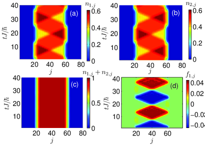
We first consider the time evolution after a brief displacement of the harmonic confinement of species 1. Figure 1 shows a compelling example of the counter-flow property of the CFSF phase. Particle-hole pairing in the CFSF state requires that the particle density of one species equals the hole density of the other: . For equal fillings, this means that the CFSF phase only occurs at half-filling, anzi . In a trapped system, the density of the CFSF phase shows a plateau at half-filling near the center of the trap. Near the edges, the system is SF. The impulse applied to species 1 is generated by the brief displacement shown in Fig. 2(a). It causes the species to move in opposite directions, as shown in Fig. 1(a) and (b). The density of species at a given position oscillates about , and the density oscillations of the two species differ in phase by . The flux is reflected at the steep SF edge of the atomic cloud. The total density distribution stays unchanged and equals one (see Fig. 1(c)). Figure 1(d) shows the local current of species 1 as a function of time. At any time, the flow occurs in only one direction. Moreover, the color image shows characteristic diamond shapes. Within each diamond, the current is nearly independent of lattice site and time, indicating a constant velocity flow. This constant flow can be understood from the constant total density of the CFSF state. As the energy due to the trapping potential at each site only depends upon the total density there, there is no potential energy cost in changing the local relative density and the observed flow moves freely within the CFSF plateau.
In Fig. 2, we show an example of the center of mass motion, , for SF, PSF, and CFSF initial states after applying a small impulse to species 1. For the SF state, Fig. 2(b) shows that only species 1 is excited immediately after the impulse. Oscillatory motion of species is only induced gradually as a result of the weak attraction between the two species. In Fig. 2(c) we show the response of the PSF phase. Due to the pairing order, both species move instantaneously and the time evolution of the center of mass is identical. The impulse on species 1 is transformed into a collective motion of both species and there is no relative motion. In the CFSF phase shown in Fig. 2(d), we see that the oscillatory motion of species is perfectly matched by an opposite or counter-flowing motion of species . We note that the sinusoidal oscillation of the center of mass is not in contradiction with the constant current flow shown in Fig. 1. Averaging over lattice sites as in Eq. (3) erases this information.
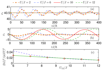
In Fig. 3 we plot the time evolution of the center of mass of both species, , and the relative center of mass, , after a brief displacement as in Fig. 2 for several interaction strengths. We increase the intra-species interaction from to and from and , with the fixed ratio ; we set . The system undergoes a phase transition from SF to CFSF around . In the SF state, the brief displacement of species 1 leads to damped oscillations in both the relative and total center of mass. The maximum amplitude of the oscillation increases with . The damping rate increases in this regime. As increases beyond the critical point, the total center of mass motion is suddenly suppressed to almost zero. On the other hand, the amplitude of the relative center of mass keeps increasing through the phase transition. The damped oscillation of the relative center of mass suddenly changes to nearly undamped above the transition.
We have also studied the dependence of the oscillation period on the interaction strength in the CFSF state. As noted previously, the density flow occurs at a constant velocity in this regime. The velocity can be estimated with two methods: the Luttinger liquid theory and an effective spin-1/2 model. Luttinger liquid theory predicts phonon-like low energy excitations with a velocity
| (4) |
where the non-universal coefficients and are assumed to be constants. For a plateau of length , the period of oscillation is then For the analysis of our simulations, we find it convenient to define the relationship based on Eq. (4),
| (5) |
In the limit of large and , we can derive another relationship for the period. Assuming the particle-hole pairs are hard-core bosons, Eq. (1) can be mapped to an effective spin-1/2 model dembler_pd . Using linear spin-wave theorylinear_spin , we obtain the phonon velocity as
| (6) |
and
| (7) |
Unlike for the Luttinger theory, this relationship does not have free parameters. Figure 3(c) shows the quantity as a function of for fixed , where and are obtained from the simulations. Overall, the quantity shows a linear trend consistent with the relationship in Eq. (5). The value is in good agreement with Eq. (7) especially for .
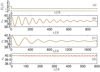
In Fig. 4 we consider the time evolution after a sudden displacement for the SF, PSF and CFSF initial states. The displacement is the same for both species. For the SF and PSF initial states, the centers of mass of both species oscillate in phase around the new minimum of the trap. The origin of the in-phase motion is different for these two initial states. For the SF state, the species respond independently to the same displacement. For the PSF state, the species respond as pairs. The oscillation frequencies for the SF and PSF states differ. This is not only because the states are confined by different trapping potentials, but also because of the larger effective mass of the pairs in the PSF state. The oscillations exhibit damping that can be attributed to strong quantum fluctuations in 1D systems Guido_damp ; ippei_damp ; trey_damp . For the CFSF state, the motion is overdamped and the center of mass remains at the original equilibrium position. The small oscillations that are visible in the time evolution of and are due to oscillations of the superfluid at the edges of the atomic cloud. For this type of displacement, the impact on both species is the same and it only affects the total density. Because the motion of the total density is suppressed for the CFSF state, the displacement can not induce a response.
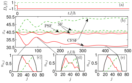
In Fig. 5 we consider a sudden displacement of the two traps in opposite directions. For the SF state, the two species oscillate around their respective new trap minima. The PSF state has no response, because the pairing order resists the force imparted by the trap displacement. The most dramatic response is in the CFSF state. Because the displaced traps act as an effective linear potential, , on the relative density, the two species are driven to move apart, until they reach the edge of the CFSF plateau. 5(c)-(e) show density profiles at different times during the time-evolution.
By increasing the displacement amplitude, we can potentially break the (anti-)pairing order. We can break the PSF pairing by applying a large opposite displacement, while the CFSF pairing can be broken by a large identical displacement. The displacement amplitude then becomes an indicator of the binding energy of the pairs in the PSF state and the anti-pairs in the CFSF state.
In conclusion, we have studied the dipole oscillation of 1D two-component Bose mixtures in an optical lattice and a weak confining harmonic potential. The oscillation is induced by displacing the harmonic confinement either briefly or suddenly. We have shown that the response of the system shows much richer features than its single-component counterpart. In the two-component system, there are three long-range orders: the superfluid, paired superfluid and counter-flow superfluid orders. For the PSF and CFSF states, the suppression of individuality leads to distinct dipole oscillations dependent on the character of the perturbation. We have shown that this is the consequence of pairing and anti-pairing ordering for the two states. For the CFSF state, which forms plateaus of constant total density, the dipole oscillations resemble the oscillation of a confined homogeneous system with free propagation between boundaries.
We acknowledge helpful discussions with Trey Porto, Steven Olmschenk, Dominik Schneble and Yoshiro Takahashi. This work was supported by the U. S. Army Research Office under the Atomtronics MURI Program. I.D. is supported by KAKENHI (22840051) from JSPS. The computational work reported here was partially done on the RIKEN Cluster of Clusters facility.
References
- (1) J. Catani, et al., Phys. Rev. A 77, 011603 (2008); B. Gadway, et al., Phys. Rev. Lett. 105, 045303 (2010); A. Widera, et al., ibid. 100, 140401 (2008); S. Ospelkaus, et al., ibid. 96, 180403 (2006); K. Gï¿œnter, et al., ibid. 96, 180402 (2006); T. Best, et al., ibid. 102, 030408 (2009); C. A. Regal, et al., ibid. 92, 040403 (2004).
- (2) A. B. Kuklov and B. V. Svistunov, Phys. Rev. Lett. 90, 100401 (2003).
- (3) A. Hu, et al., Phys. Rev. A 80, 023619 (2009).
- (4) A. Hu, et al, Phys. Rev. A 81, 063602 (2010).
- (5) L. Mathey, et al., Phys. Rev. A 79, 011602 (2009); ibid. 79, 013609 (2009).
- (6) B. Paredes and J. I. Cirac, Phys. Rev. Lett. 90, 150402 (2003).
- (7) A. B. Kuklov, et al., Phys. Rev. Lett. 92, 030403 (2004); ibid. Phys. Rev. Lett. 92, 050402 (2004); Phys. Rev. A 69, 025601 (2004).
- (8) E. Altman, et al., New J. Phys. 5, 113 (2003).
- (9) Ş.G. Sï¿œyler, et al., New J. Phys. 11, 073036 (2009); T. Ohgoe and N. Kawashima, Phys. Rev. A 83, 023622 (2011); C. Trefzger, et al.., Phys. Rev. Lett. 103, 035304 (2009); C. Trefzger, et al., New J. Phys. 12 093008 (2010), E. K. Dahl et al., Phys. Rev. B 77, 144519 (2008).
- (10) D. McKay and B. DeMarco, New J. Phys. 12, 055013 (2010).
- (11) C. D. Fertig, et al., Phys. Rev. Lett. 94, 120403 (2005).
- (12) T. Stï¿œferle et al., Phys. Rev. Lett. 92, 130403 (2004); E. Haller et al., Nature 466, 597 (2010).
- (13) S. Burger et al., Phys. Rev. Lett. 86, 4447 (2001); D. McKay, et al., Nature 453, 76 (2008).
- (14) G. Vidal, Phys. Rev. Lett. 91, 147902 (2003); ibid. 93, 040502 (2004); S. R. White, et al., Phys. Rev. Lett. 93, 076401 (2004).
- (15) I. Danshita and C. W. Clark, Phys. Rev. Lett. 102, 030407 (2009).
- (16) S. Montangero, et al., Phys. Rev. A 79, 041602(R) (2009).
- (17) See, e.g., R. M. White, Quantum Theory of Magnetism (Springer, New York, 2006).