Exploiting Interference Alignment in Multi-Cell Cooperative OFDMA Resource Allocation
Abstract
This paper studies interference alignment (IA) based multi-cell cooperative resource allocation for the downlink OFDMA with universal frequency reuse. Unlike the traditional scheme that treats subcarriers as separate dimensions for resource allocation, the IA technique is utilized to enable frequency-domain precoding over parallel subcarriers. In this paper, the joint optimization of frequency-domain precoding via IA, subcarrier user selection and power allocation is investigated for a cooperative three-cell OFDMA system to maximize the downlink throughput. Numerical results for a simplified symmetric channel setup reveal that the IA-based scheme achieves notable throughput gains over the traditional scheme only when the inter-cell interference link has a comparable strength as the direct link, and the receiver SNR is sufficiently large. Motivated by this observation, a practical hybrid scheme is proposed for cellular systems with heterogenous channel conditions, where the total spectrum is divided into two subbands, over which the IA-based scheme and the traditional scheme are applied for resource allocation to users located in the cell-intersection region and cell-non-intersection region, respectively. It is shown that this hybrid resource allocation scheme flexibly exploits the downlink IA gains for OFDMA-based cellular systems.
I Introduction
This paper studies orthogonal frequency-division multiple access (OFDMA) based cellular systems with universal frequency reuse, in which adjacent cells share the same frequency band for simultaneous transmission to improve the spectrum efficiency. However, for such systems, the inter-cell interference (ICI) control becomes crucial, which has recently drawn significant attention (see, e.g., [1] and references therein). In general, there are two approaches to cope with the ICI in multi-cell systems [1]: interference coordination and network MIMO (multiple-input multiple-output). The former approach mitigates the ICI via cooperative resource allocation across different cells based on their shared channel state information (CSI), where the latter approach utilizes the ICI via baseband-level signal cooperation for joint encoding and/or decoding at the base stations (BSs). Although promising from the viewpoint of theoretical performance, network MIMO requires the baseband time synchronization as well as message sharing among different BSs, which is challenging to implement for existing cellular systems. As such, in this paper, we focus our study on the interference coordination approach.
Existing resource allocation schemes (e.g., [2, 3, 4]) for multi-cell OFDMA systems have adopted a subcarrier-separation approach, whereby all subcarriers (SCs) are treated as separate dimensions for user selection and power allocation. However, a recent study [5] has revealed that for a parallel interference channel (PIC) consisting of parallel Gaussian interference subchannels, joint precoding over parallel subchannels improves the sum capacity over the case without precoding for some specially designed channel realizations, i.e., the PIC is in general non-separable. Motivated by this finding, in this paper, we study a new approach to design cooperative resource allocation for multi-cell OFDMA, by exploiting frequency-domain precoding over parallel SCs.
The precoding technique used for the PIC in [5] is known as interference alignment (IA). By properly aligning the interference at the receivers via linear precoding at the transmitters, for -user Gaussian interference channels, it is shown in [6] that the IA technique achieves a sum-rate multiplexing gain of per time, frequency or antenna dimension. In other words, IA enables interference-free communications for all the users provided that each user utilizes only half of the available degrees of freedom (DoF). Although IA has been largely investigated in cases with time-domain symbol extension or with spatial beamforming via multiple antennas, how to exploit frequency-domain IA to design efficient OFDMA resource allocation in a multi-cell scenario remains open and has been rarely studied in the literature, to our best knowledge.
In this paper, we investigate the problem of exploiting IA in cooperative resource allocation in OFDMA-based cellular systems. For the purpose of exposition, we study the OFDMA downlink transmission in a simplified three-cell system with universal frequency reuse. All the BSs and user terminals are assumed to be each equipped with a single antenna, and the system is thus modeled by a SISO (single-input single-output) interfering broadcast channel (BC). With the objective of maximizing the system weighted sum-rate, the joint optimization of frequency-domain precoding via IA, SC scheduling with user selection, and power allocation is studied in this paper. From the numerical experiments under a symmetric channel setup (with unit average channel gain for all in-cell direct links and the same average channel gain for all cross-cell interference links), we find that the IA-based resource allocation scheme demonstrates its advantages over the traditional scheme without frequency-domain precoding only when the cross-cell link has a comparable strength as the direct link, and the receiver signal-to-noise (SNR) is sufficiently large. Motivated by this observation, a hybrid scheme is proposed for practical cellular systems with heterogenous channel conditions. In this hybrid scheme, the total spectrum is divided into two subbands, over which the IA-based scheme and the traditional scheme are applied for resource allocation to users located in the cell-intersection region and cell-non-intersection region, respectively. It is shown by simulation results that this hybrid scheme can be flexibly designed to exploit the downlink IA gains for OFDMA-based cellular systems with cooperative interference control.
II System Model
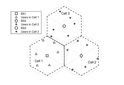
As shown in Fig. 1, for the purpose of exposition, we consider a three-cell system, in which all cells share the same frequency band for simultaneous downlink transmission. In each cell, OFDMA is assumed for the downlink transmission, where the total shared bandwidth is equally divided into SCs indexed by . The users in each cell are scheduled for transmission over orthogonal SCs, while the users’ SC allocation are allowed to change from one scheduling time-slot to another. A slow fading environment is assumed, in which all the channels involved in the system are constant during each scheduling slot, but can vary from slot to slot. In one particular slot, each SC is assumed to be used by at most one user inside each cell due to OFDMA, but allowed to be shared by users from different cells due to universal spectrum sharing. We use to represent the set of three cells, and denote the user associated with Cell as , where is the total number of users in Cell . In addition, the complex downlink baseband channel response from the BS of Cell to user in Cell at SC is denoted as . Each BS is assumed to have a total transmit power constraint given by . Furthermore, we use the matrix of size to denote the SC allocation in the whole system, of which the -th element, denoted by with , indicates the user assigned to SC in Cell .
Note that for all the resource allocation schemes presented in the sequel, we assume that there exists a central controller that collects all the CSI in the network via dedicated feedback channels or backhaul networks, and is thus enabled to perform a centralized resource allocation.
III Traditional Resource Allocation
In this section, we present one traditional scheme for cooperative resource allocation in the studied three-cell system, which is based on the subcarrier-separation principle, i.e., all the SCs are treated as separate dimensions for user selection and power allocation. First, supposing that , the baseband signal received by user at SC is written as
| (1) |
where is the complex symbol transmitted by BS at SC , with denoting the power allocated, and is the circularly symmetric complex Gaussian (CSCG) noise at the receiver with zero mean and variance .
The signal-to-interference-plus-noise-ratio (SINR) of user in Cell at SC is given by
| (2) |
where . Then, the maximum achievable transmission rate at this SC is given by (normalized to be in bps/Hz)
| (3) |
Hence, the problem of maximizing the weighted sum-rate of all users in the system can be expressed as
| (4) |
where is a -by- power allocation matrix consisting of column vectors , denotes the set of all possible SC allocation matrices for , and is the (non-negative) weight of user in Cell .
The problem in (4) can be shown to be non-convex over due to the non-concave rate functions in (3) even for a fixed , and is thus in general non-convex with arbitrary . Nevertheless, the Lagrange duality method can be applied to this problem to obtain a set of close-to-optimal solutions, which, as verified by our numerical experiments, usually converge to the optimal solutions when the number of SCs becomes large (i.e., the duality gap converges to zero as ). More specifically, the partial Lagrangian of problem (4) is given by
| (5) |
where is the power constraint vector, and is the vector of non-negative dual variables. The Lagrange dual function then becomes
| (6) |
Thus, the dual problem can be defined as
| (7) |
For a given vector , can be simplified as
| (8) |
where
| (9) |
The maximization problem in (8) is thus decoupled into parallel per-SC based subproblems, which are given by
| (10) |
where with denoting the th column of . The solutions to the problems in (10) have been studied in e.g. [2, 3, 4] by various iterative methods; the details are thus omitted for brevity. Last, subgradient-based methods such as the ellipsoid method [4] can be used to iteratively search for the optimal in the dual problem to make the corresponding power allocation solutions of the problems in (10) satisfy all the per-BS power constraints.
Note that the above joint user SC and power allocation scheme is based upon the premise that there is no frequency-domain precoding over parallel SCs at each BS. Next, we will propose an IA-based resource allocation scheme with frequency-domain precoding.
IV IA-Based Resource Allocation
In this section, we propose a new scheme for cooperative multi-cell OFDMA downlink resource allocation with IA-based frequency-domain precoding. Specifically, two non-adjacent SCs, denoted by , are grouped to form the th SC-pair, which supports simultaneous downlink transmission to three users, denoted by , each being selected from one of the three cells, via linear transmit precoding over the two chosen SCs. Note that for notational convenience, we use to denote the SC-pair index in this section, where (assume that is an even number).
Without loss of generality, we consider the baseband signals for user over the th SC-pair , which are given by
| (11) |
| (12) |
where with being the precoder weights for user of Cell over the th SC-pair, and being the information-bearing symbol for user . Together, (11) and (12) can be further expressed in the matrix form shown as follows:
| (13) |
where is the precoding vector for user ,
| (14) |
is the equivalent (diagonal) channel matrix from BS to user , and is the noise vector for user , all defined for the th SC-pair. Based on the analysis for user , the downlink transmission from the three BSs to their respective users over the -th SC pair can be represented by
| (15) |
. At the receiver of user , an interference suppression vector is pre-multiplied with the received signal to eliminate the inter-cell interference, which leads to the following equivalent channel model:
| (16) |
where
| (17) |
| (18) |
| (19) |
Note that (16) bears a similar expression as (1), with being equivalent channel gains for direct and inter-cell links, respectively. Assuming that are all of unit norm and , the achievable rate over the th SC-pair for user is given by
| (20) |
where .
Since searching for the optimal SC-pairs over is computationally prohibitive, we use a pre-determined SC-pairing method as follows: for the th SC-pair, the two SCs are given by . This paring method is to maximize the frequency gap between the two SCs in each pair, so as to maximally exploit the frequency-domain channel diversity. With the above SC-pairs, the weighted sum-throughput of the three-cell system is obtained by solving the following problem:
| (21) |
where with , and is a -by- matrix with its th column vector specifying the users selected from the three cells for the th SC-pair. Note that and are similarly defined as and in Section III, respectively, while it is worth noting that here refers to the SC-pair index instead of the SC index in Section III.
Similarly as the derivation given in Section III, the problem in (21) can be decoupled into parallel per-SC-pair based resource allocation subproblems in the dual domain, i.e.,
| (22) |
where is the vector of non-negative dual variables associated with the per-BS power constraints.
Consider first the case when perfect IA is achievable, i.e., all the inter-cell interference gains in (18) become zero. In this case, the residual interference (RI) terms in the denominator of (20) vanish, which results in decoupled user power optimization in (22) for each SC-pair. Specifically, by letting
| (23) |
we obtain the following optimal power allocation:
| (24) |
which resembles the conventional “water-filling” solution.
However, to our best knowledge, no closed-form expressions for and that achieve the perfect IA have been found for our studied scenario. Thus, we resort to the existing “Distributed Interference Alignment” algorithm in [7] to compute the transmitter precoding and receiver interference suppression vectors given the CSI for any set of three users and SC-pair. Based on our numerical experiments, it is found that with this algorithm, small but non-zero RI usually exists for the equivalent three-user MIMO interference channel given by (15), probably due to the particular structure of diagonal direct-link and cross-link channel matrices. In this case with the RI, the problem in (21) can be solved similarly as that in (4) in the case of traditional scheme with virtually instead of SCs. For brevity, the details are omitted.
Next, we compare the performance of the tradition resource allocation scheme in Section III and the newly proposed IA-based scheme in terms of the system sum-rate (i.e., ). In order to gain intuition from the numerical results, we assume an ideal symmetric channel model for the three-cell system in Fig. 1, in which ’s are modeled as independent CSCG random variables for , and for , respectively. In addition, it is assumed that , , ’s are same for all three BSs, and .
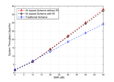
Fig. 2 shows the sum-rate versus the average direct-link SNR at each user’s receiver with , i.e., the direct-link has the same average power gain as the cross-link in the symmetric channel setup. It is observed that the IA-based scheme with the RI performs slightly worse than that without the RI (assuming perfect IA and thus neglecting the RI terms in (20)). In addition, the IA-based scheme is observed to perform better than the traditional scheme when SNR is larger than 15dB, and eventually achieve a DoF gain of compared to the traditional scheme when SNR goes to infinity. This DoF gain can be explained as follows: For the IA-based scheme (without RI), three data streams are transmitted without mutual interference over each SC-pair consisting of two SCs, while for the traditional scheme, when the SNR is sufficiently high, the optimal SC allocation tends to be orthogonal, i.e., each SC is assigned to only one user from a particular cell, while no users from the other two cells are assigned to the same SC.
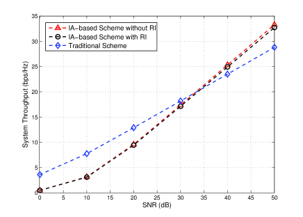
Similar observations are obtained in Fig. 3 for the symmetric channel setup with . However, in this case with weak cross-link interference, the SNR threshold beyond which the IA-based scheme outperforms the traditional scheme increases from 15dB in the previous case of to 35dB in the present case. In addition, the IA-based scheme is observed to perform notably worse than the traditional scheme from low to moderate SNRs (0-20dB) that are typical for cellular systems. This performance gap is because the IA-based scheme always transmits three data streams over two SCs regardless of the SNR, while the traditional scheme can support up to 3 users each from one cell at any single SC when the inter-cell interference is sufficiently weak as in the present case.
V Hybrid Scheme
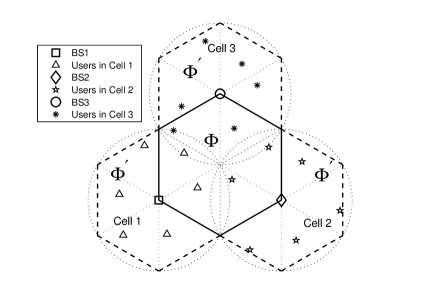
The numerical results for the symmetric channel setup reveal that the IA-based scheme with frequency-domain precoding provide throughput gains over the traditional scheme without precoding only when the cross-link has a comparable strength with the direct-link and the operating SNR is sufficiently high. The above conditions are rarely satisfied in practical cellular systems due to randomized user locations and distance-dependent signal attenuation. This motivates our following hybrid scheme for resource allocation in a three-cell system with heterogenous channel conditions (cf. Fig. 4): For the users located within the six sectors (two from each cell) that lie in the intersection region of the three cells, namely cell-intersection region (CIR), a dedicated set of SCs, denoted by , is reserved over which the IA-based scheme is applied, since in this region the aforementioned operating conditions for IA are more likely to be satisfied; in contrast, for the rest of the users located in the cell-non-intersection region (CNIR), the remaining set of SCs, denoted by , is allocated over which the traditional scheme is applied. For example, we can design the sizes of and to be proportional to the number of sectors in the CIR and CNIR, respectively, i.e., , and thus .
Similar to the problems formulated in (4) and (21), the following problem maximizes the system weighted sum-rate in the case of hybrid scheme (thus similarly solvable):
| (25) |
where and are given in (3) and (20) respectively; the power and SC allocations are similarly defined as , and is used to index the SC-pairs in .
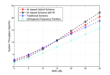
Fig. 5 shows the system sum-rates for various schemes in a three-cell system with heterogenous channels with distance-dependent attenuation (the attenuation factor is two). One additional traditional scheme, namely orthogonal frequency partition (OFP), is also considered, which allocates each cell of the total spectrum for orthogonal downlink transmission. It is assumed that , , and the SNR shown in the figure is the average SNR measured at the cell edge. It is observed that the hybrid scheme can exploit the advantages of both traditional and IA-based resource allocation schemes for low and high SNRs, respectively, and thus achieve an overall more balanced performance. It is also worth noting that by changing the relative sizes of and , alternative designs of the hybrid scheme can be flexibly obtained to maximize the throughput for a given SNR value.
VI Conclusion
This paper studies the downlink cooperative interference control in cellular OFDMA systems. A new IA-based resource allocation scheme is proposed, which jointly optimizes the frequency-domain precoding, subcarrier user selection, and power allocation to maximize the system throughput. For practical cellular systems with heterogenous channel conditions, a hybrid scheme is proposed to exploit the downlink IA gains.
References
- [1] D. Gesbert, S. Hanly, H. Huang, S. Shamai, O. Simeone, and W. Yu, “Multi-cell MIMO cooperative networks: A new look at interference,” IEEE J. Sel. Areas Commun., vol. 28, no. 9, pp. 1380-1408, Dec. 2010.
- [2] L. Venturino, N. Prasad, and X. Wang, “Coordinated scheduling and power allocation in downlink multicell OFDMA networks,” IEEE Trans. Veh. Tech., vol. 58, no. 6, pp. 2835-2848, July 2009.
- [3] W. Yu, T. Kwon, and C. Shin, “Joint scheduling and dynamic power spectrum optimization for wireless multicell networks,” in Proc. 44th Conf. Info. Science Sys. (CISS), Princeton, NJ, March 2010, pp. 1-6.
- [4] B. Da and R. Zhang, “Cooperative interference control for spectrum sharing in cellular OFDMA systems,” to appear in Int. Conf. Commun. (ICC), June 2011, Kyoto, Japan. (Available [online] at http://arxiv.org/abs/1102.3579)
- [5] V. R. Cadambe and S. A. Jafar, “Multiple access outerbound and the inseparability of parallel interference channels,” in Proc. IEEE Global Commun. Conf. (GLOBECOM), Dec. 2008, pp. 1-5.
- [6] V. R. Cadambe and S. A. Jafar, “Interference alignment and degrees of freedom of the K-user interference channel,” IEEE Trans. Inf. Theory, vol. 54, no. 8, pp. 3425-3441, Aug. 2008.
- [7] K. Gomadam, V. R. Cadambe, and S. A. Jafar, “Approaching the capacity of wireless networks through distributed interference alignment,” in Proc. IEEE Global Commun. Conf. (GLOBECOM), Dec. 2008, pp. 1-6.