Structural Transitions and Dynamical Regimes for Directional Locking of Particles Driven Over Periodic Substrates
Abstract
We numerically investigate collective ordering and disordering effects for vortices in type-II superconductors interacting with square and triangular substrate arrays under a dc drive that is slowly rotated with respect to the fixed substrate. A series of directional locking transitions occur as the drive rotates when the particle motion locks to symmetry directions of the substrate, producing a series of steps in the velocity-force curves. The locking transitions coincide with structural transitions between triangular, square, smectic, or disordered particle arrangements, which can be identified using the structure factor. We show that the widths of the locking steps pass through local minima and maxima as a function of the ratio of the number of particles to the number of substrate minima. Unlike a static system, where matching effects occur for simple integer commensuration ratios, our system exhibits dynamical commensuration effects where an integer number of particle chains flow between one-dimensional lines of substrate minima. As the system enters and exits the locking steps, order-disorder transitions in the structure of the moving particle assembly occur. We identify two distinct symmetry locking regimes as a function of substrate strength which produce different locking step characteristics. For weak substrates, all the particles are in motion and a portion of the particles flow through the substrate minima, leading to structural transitions at certain driving angles. For strong substrates, some particles are permanently pinned while the remaining particles flow around them. At the crossover between these two regimes of substrate strength, some or all of the locking steps are destroyed due to the onset of chaotic plastic flow which produces pronounced changes in the transport characteristics. We show that similar effects occur for colloidal particles driven over square and triangular substrate arrays.
pacs:
74.25.Qt,82.70.Dd1 Introduction
There have been numerous studies of collections of driven particles interacting with periodic substrates in which directional or kinetic locking of the particle motion occurs [1, 2, 3, 4, 5]. Here, some or all of the particles move along a symmetry direction of the substrate even though the external driving force is not applied along the symmetry direction. This effect was first observed in a superconducting vortex system with a square pinning array in [1]. The direction of drive was rotated with respect to the substrate by applying one dc drive along a major symmetry axis of the array while gradually increasing a second perpendicular dc drive . The initial dc drive was strong enough to cause all the vortices to flow over the substrate so that there were no pinned vortices. As increased, the -component of the response did not increase smoothly as would be expected in the absence of pinning, but instead increased in a series of steps which formed as the vortex motion locked to different symmetry directions of the substrate. For a square substrate lattice, locking steps appear whenever , where and are integers, giving a devil’s staircase structure. Although this initial study was performed for superconducting vortices, in [1] it was suggested that similar effects should occur for other systems of particles moving over periodic substrates at varied drive angles, such as colloidal particles moving over optical substrates. A later study predicted similar effects for the motion of classical charged particles over a two dimensional periodic potential array [2]. The first experimental observation of this type of symmetry locking was obtained for colloidal particles driven at different angles over an optically generated square substrate [3]. The locking, termed kinetic locking in [3], was proposed as a novel fractionation method for separating different colloidal species which could be effective whenever one species locked much more strongly than the other to the symmetry direction of the optical array. Such separation was specifically demonstrated in other experiments with colloidal particles moving over periodic substrates [4]. Following these works, there have been numerous experiments and simulations showing symmetry locking for particles moving on periodic substrates [5, 6, 7, 8, 9, 10, 11, 12, 13, 14, 15, 16, 17, 18, 19, 20], as well as new proposals for achieving a similar effect with nanoparticles [21]. Most of these studies [2, 3, 4, 5, 7, 8, 9, 10, 11, 12, 13, 14, 15, 16, 17, 18, 19, 20] involved noninteracting particles and did not consider collective effects. In the superconducting system studied in [1], the particle-particle interactions are sufficiently long ranged that collective particle interactions play an important role in the response of the system, producing different types of triangular or square orderings. This suggests that there could be a rich variety of collective behaviours and even different types of symmetry locking for particles driven over periodic substrates that have not been explored yet.
In addition to the colloidal work, symmetry locking effects have been further studied for superconducting vortices in numerical simulations [22, 23] and have also been observed experimentally [22, 24, 25, 26]. For systems in which the particles are strongly interacting, dynamical symmetry locking effects can occur even when the particles are moving over a random substrate provided that the particle-particle interactions are strong enough to overcome the randomness of the substrate and produce a triangular ordering of the moving particles [27, 28]. The initial triangular ordering of a lattice of strongly interacting vortices results in directional locking steps whenever the direction of the external drive matches one of the lattice vectors of the triangular vortex lattice. Under these conditions, the transverse depinning threshold for motion perpendicular to the lattice symmetry directions is enhanced. This effect was predicted in theoretical work on the moving vortex Bragg glass where the vortex lattice maintains its triangular ordering [27] and was also observed in numerical simulations for systems with weak random substrates [28]. The appearance of a critical or nonzero transverse depinning threshold due to directional locking has also been predicted to occur for frictional systems of sliding elastic manifolds on periodic surfaces [29, 30, 31]. Vortices and colloids driven over quasicrystalline arrays at varied angles also show directional locking effects where the motion locks to certain orientational degrees of freedom of the lattice even though the substrate has no long-range translational order [32].
Since numerical models of vortex and colloidal systems have proved to be valuable systems for understanding the general behaviour of particles moving over periodic substrates, in this work we use the motion of vortices and colloids to study several aspects of collective effects in symmetry locking that have not been considered previously. The initial study of the symmetry locking effect for a square substrate was performed in the limit where all the vortices were moving [1]. It would be interesting to understand how the locking effects change as the ratio of the external drive to the pinning strength is varied, particularly when a portion of the particles become pinned for stronger substrates. One example of a system exhibiting partial pinning is a superconductor with an applied magnetic field of , where is the field at which the number of vortices in the sample equals the number of substrate minima in the sample. If each substrate minima can trap only one vortex, then for , a portion of the vortices occupy interstitial locations between the substrate minima. In order to move under an applied current, these interstitially confined vortices must either flow along the occupied rows of pinning by displacing the pinned vortices, or they can flow through the interstitial regions between the pinning sites [33, 34, 35, 36]. Interstitial vortices, when present, are much more mobile than the pinned vortices and depin at a lower driving threshold than the vortices at the pinning sites [33, 36, 37]. The interstitial vortices may exhibit dynamical locking effects as the direction of the drive is changed; however, it is also possible that for some driving directions the moving interstitial vortices can cause a portion of the vortices at the pinning sites to depin, disrupting or changing the locking effects. The initial symmetry locking study of vortices moving through a square pinning array [1] focused only on fields very near , and it is not known how the locking effects would change for higher fields or for varied particle density with a fixed pinning density. It might be expected that the strength of the locking effects would simply decrease for increasing particle density; however, in this work we show that the locking actually undergoes particle density-induced oscillations related to dynamical commensurability effects.
2 Simulation
We model a two-dimensional system with periodic boundary conditions. For the case of superconducting vortices, we consider a sample of size , where length is measured in units of the London penetration depth . The motion of an individual vortex evolves according to the overdamped equation
| (1) |
Here is the location of vortex and is the damping coefficient ,where is the sample thickness, is the superconducting coherence length, is the normal state resistivity, and is the flux quantum. The first term on the right is the vortex-vortex interaction force given by where is the modified Bessel function, , , and . Since the Bessel function diverges at the origin, we place a cutoff on the interaction force at ; in practice, the vortices do not approach each other this closely. The repulsive force falls off exponentially at larger distances so we place a maximum interaction distance cutoff at to increase the computational efficiency. The periodic substrate is modelled as parabolic potential traps or pinning sites of radius and maximum strength . The vortex-substrate interaction has the form . Here is the Heaviside step function, is the location of pinning site , , and The pinning sites are placed in a triangular or square arrangement.
The initial vortex configurations are obtained by simulated annealing, where we form a high temperature molten state by applying Langevin kicks to the vortices, and slowly cool the sample to . We anneal by decreasing in increments of with a waiting time of simulation time steps between increments. After annealing, we apply an external force in the form of a drive applied at an angle that changes very slowly,
| (2) |
Here the force amplitude is , , and is the frequency of rotation, which is taken to be small. The velocity response in the and directions can be obtained by measuring the average vortex velocities and . We measure the velocity as a function of the drive angle . We focus on the case of low frequencies to avoid any transient effects in the vortex dynamics. We have specifically checked that the simulated annealing time is long enough that the initial vortex configurations do not change for slower annealing rates and that the rotation frequency is small enough that there are no changes in the widths of the directional locking steps for lower values of .
For the colloidal simulations we use the same type of overdamped equation of motion and the same form for the pinning substrates. The main difference is the particle-particle interactions, which are still repulsive but have the Yukawa form with , where , is the solvent dielectric constant, is the effective charge of each colloid and is the screening length. In this case lengths are measured in units of and forces in units of .
3 Structural Transitions and Directional Locking
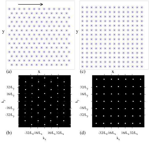
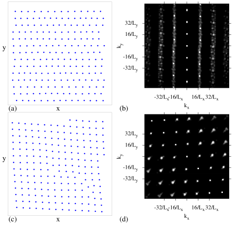
In figure 1(a) we show a snapshot of the system for a triangular pinning array at and zero drive. The arrow indicates the initial direction of the applied force, which rotates counterclockwise with time. In figure 1(b) we plot the corresponding structure factor for the vortex positions,
| (3) |
Here, six peaks appear which are indicative of the triangular ordering of the vortex lattice. In figure 1(c) we illustrate the nondriven phase for a square pinning array at , along with the corresponding structure factor in figure 1(d).
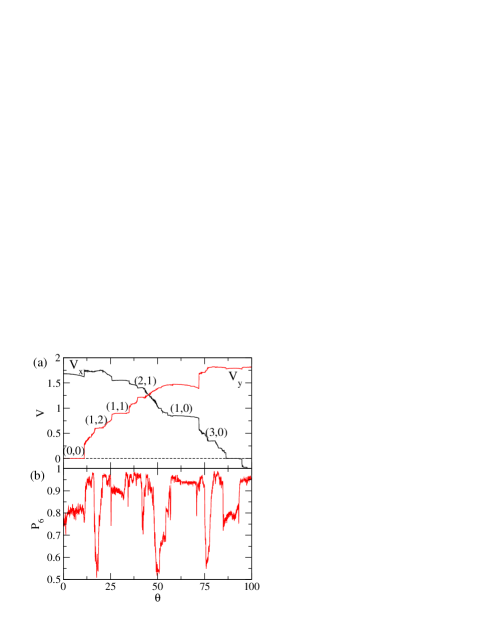
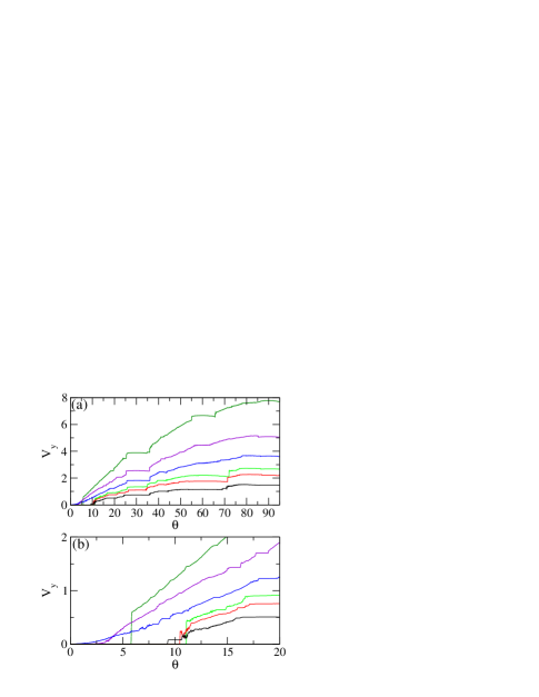
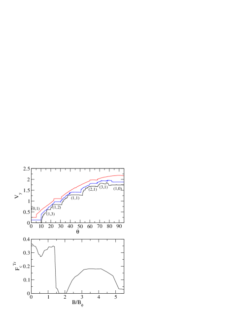
We first consider directional locking on a triangular pinning substrate, which occurs at driving angles . The dominant locking angles fall at for , and for , . We use the notation to denote the locking regions. In figure 2(a) we plot and versus for a sample with at . In the absence of pinning, the velocities would follow a smooth sinusoidal curve with starting from zero and reaching a maximum at when goes to zero. Figure 2(a) shows that in the presence of pinning, both and pass through a series of pronounced steps and jumps. For , the motion is locked in the -direction with a finite and . The value of the component of the driving force at the end of the step when the locking to the direction is lost is the critical transverse depinning force corresponding to the locking. At the end of the step there is a discontinuous jump in to a finite value which is correlated with a sudden increase in . The increase in occurs even though the component of the driving force is decreasing. Over the range , increases, passing through a small step near . A large locking step is centred at corresponding to the locking. A second strong step in both and occurs at at the locking. When the system exits this step, jumps up and jumps down. In figure 2(b) we plot the fraction of sixfold coordinated particles as a function of . Here , where the coordination number of each particle is obtained from a Voronoi construction. In the absence of pinning, when the vortices form a triangular lattice. On the step, , indicating that the system does not have complete triangular ordering and that some dislocations must be present. Along the step, , but dips at the start and the end of the step. For the first half of the step, has a low value, and then for the second half of the step increases.
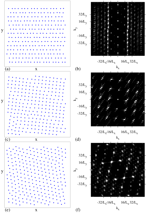
To better characterize the different vortex structures in the locking regimes, in figure 3(a) we plot the vortex positions on the step for the system in figure 2, and in figure 3(b) we show the corresponding . Here the particles are moving in one-dimensional channels along the pinning rows in the -direction. has smectic features with well spaced peaks along the -axis indicating that periodic spacing of the particles along the direction is induced by the underlying rows of pinning. Particles in adjacent rows can slip past each other along the direction. In this regime, due to the formation of aligned dislocations between adjacent rows. Similar smectic ordering has previously been observed for vortices moving over random pinning arrays [38, 39, 40, 41] and is associated with a transverse depinning barrier [38, 39, 42]. For vortices moving over pinning arrays with driving applied only in the -direction, moving smectic phases are also possible at finite temperature [43, 44]. In figure 3(a), the smectic ordering occurs when all the vortices are confined to move only along the pinning rows and not between the rows of pinning. Since , this means that the vortex lattice spacing in the direction along the pinning rows must be smaller than the lattice spacing in the direction transverse to the pinning rows, resulting in an effectively anisotropic interaction between the vortices. Additionally, certain moving channels may contain more vortices than other moving channels, creating dislocations in the vortex lattice. Along the step, the system has a smectic ordering similar to that shown in figure 3(a,b) but tilted by with respect to the axis.
Figure 3(c,d) illustrates the vortex positions and on the locking step. In this case the vortex lattice has square symmetry with some disordered regions which produce some smearing in . The formation of the square ordering is what causes the drop in on the step shown in figure 2(b). The Voronoi construction we use to determine the particle coordination numbers can accurately identify triangular ordering but is not well suited for measuring slightly disordered square ordering such as that found on the step. As a result, shows large fluctuations on the step even though the measurement indicates the presence of a consistent square ordering throughout the step.
In figure 3(e,f) we show the vortex positions and for , a non-step region with . The system has triangular ordering as indicated by the sixfold peaks in . Typically the vortex channeling effect is lost in the non-step regions. For sufficiently weak pinning the vortex-vortex interactions dominate over the vortex-pin interactions and the vortices form a mildly disordered triangular lattice, resulting in large values of .
Figure 2(a) shows a prominent locking step at . Along the step, decreases with increasing until at there is a sharp jump up in along with a sharp jump down in at the end of the locking step. This shows that directional locking can induce negative differential conductivity, where the driven particles actually move more slowly in the direction of drive when the external driving force is increased. Negative differential conductivity has been observed in simulations and experiments for vortices driven in a fixed direction over periodic pinning arrays [36, 45]. The negative differential conductivity effect which we observe here for triangular pinning did not appear in previous simulations which considered only square pinning [1]. More recently a study with two crossed channels showed that a phase locking state could be realized that has velocity-force curves very similar to those in figure 2(a) and that also exhibits negative differential conductivity [46].
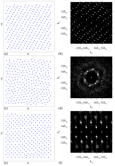
In figure 2(b), the locking step has dips in at the start and end of the step, while along the step . The dips are caused by the sudden disordering of the particles at the transition into and out of the locked regime, and are associated with a strongly anisotropic vortex lattice structure. In figure 4(a,b) we show the particle positions and for on the step. The particles again form one-dimensional channels and move along the pinning rows. There are some dislocations present in the vortex lattice which result in smectic ordering; however, there is a considerably larger amount of ordering in the direction transverse to the locking direction than along the locking direction, causing the amount of smearing in to be less than that observed for the step. Figure 4(c,d) illustrates the system at the dip in right at the end of the locking step. The lattice structure is disordered, producing a ringlike structure in . Smeared sixfold peaks remain visible in due to the anisotropic nature of the liquidlike structure.
Figure 2(a) shows that the locking step is accompanied by a strong dip in . Along this step a square vortex lattice forms which is similar to the one illustrated for the locking step in figure 3(c,d). There is another locking region centred at where and shows a cusp feature. Along this step , and figure 4(e,f) shows that a distorted square lattice appears. As increases above , the system cycles back through the same transitions.
4 Density Dependence and Dynamic Commensuration Effects
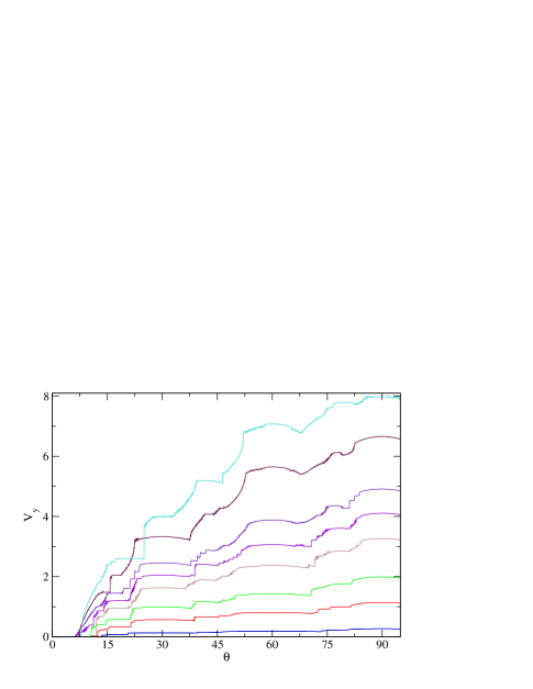
We next consider the effect of particle density on the directional locking. In figure 5(a) we plot for the same triangular pinning system from figure 2 with for different vortex densities , 1.26, 1.5, 2.0, 2.78, and . As the vortex density increases, the smaller steps become narrower and more difficult to resolve; however, the steps at , , , and remain clearly visible. Different steps respond differently to changes in . For example, for the and steps are present but at these steps are lost. In contrast, the step at is present at all the values of .
The and steps reappear for and grow in width with increasing vortex density up to . Figure 5(b) shows a blowup of the region around the step indicating that at the width of the step drops to zero but that at the step reappears, producing a crossing in the versus curves. In figure 6 we plot the width of the step versus , where is defined as , the component of the force at which the step disappears. For low , is large since the system is in the single particle limit when the vortex-vortex interactions are weak. As increases, deceases until it reaches a local minimum at . This is followed by a local maximum in at , after which decreases nearly to zero for . A broad maximum in appears for before drops again at higher . This nonmonotonic behaviour of contrasts with the critical depinning force observed in a system with random pinning, which monotonically decreases to a saturation level with increasing vortex density. In recent studies of directional locking for vortices moving over quasicrystalline pinning arrays [32], a nonmonotonic behaviour of the width of the first locking step was observed as a function of . In the quasicrystalline case, the width of the step never drops completely to zero; however, a broad local minimum occurs at and a broad peak appears for , similar to the features shown in figure 6.

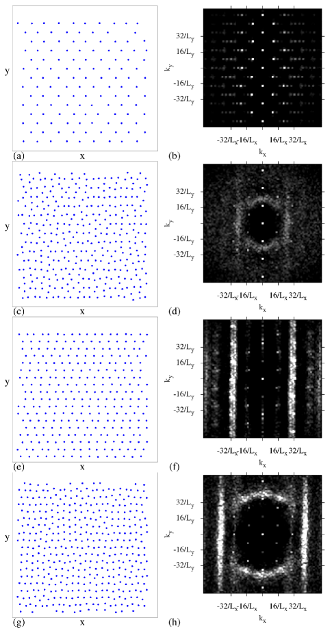
In figure 7 we illustrate the vortex positions and at different vortex densities for the system in figure 6 along the step. At , figure 7(a) shows that a disordered triangular lattice forms. For lower fillings , the ordering becomes more smectic-like as the vortex-vortex interactions are reduced in strength. Smectic ordering also appears close to the peak in at , as shown in figure 3(a,b). In the region where drops to zero, the lattice is disordered and has a ringlike structure, as shown in figure 7(c,d) for . There is a tendency for some vortices to form stripe-like structures aligned with the direction, generating weak peaks in along the -axis and making the liquidlike structure anisotropic. At , near the middle of the broad peak in in figure 6, figure 7(e,f) indicates that the lattice has smectic ordering, while at where drops again, figure 7(g,h) shows that the lattice is disordered with some partial direction alignment. For the vortex lattice has smectic structure while at vortex densities where is low or zero, the vortex lattice is disordered or nematic.
In recent work on the directional locking of vortices moving over quasicrystalline arrays, for values of where is enhanced, the vortices have smectic ordering, while for higher where the value of drops, the system becomes partially disordered [6]. This is very similar to what we observe for the triangular pinning arrays, as shown in figure 6. In the quasicrystalline array system, square vortex lattices form at fillings where passes through a local minimum but remains finite. At the local minimum in that we observe in figure 6 at , the vortex lattice is not square but it does have a distorted triangular ordering, as shown in figure 7(a,b). We note that the dynamical ordering which occurs just above a critical transverse depinning force differs from the dynamical structure that forms just above the longitudinal depinning force. In the case of the transverse depinning, the vortices are already moving and may form a dynamically ordered configuration even before transverse depinning occurs. In contrast, for the longitudinal depinning, the vortices start from a pinned state. For longitudinal depinning, peaks in the critical current occur at matching fields and fractional matching fields , where and are integers [33, 34, 35, 47]. Figure 6 shows that the peaks in the transverse critical current do not fall at integer matching fields or fractional matching fields, so the local maxima and minima must arise due to some other type of commensuration effect and not due to simple matching between the number of vortices and the number of pinning sites.
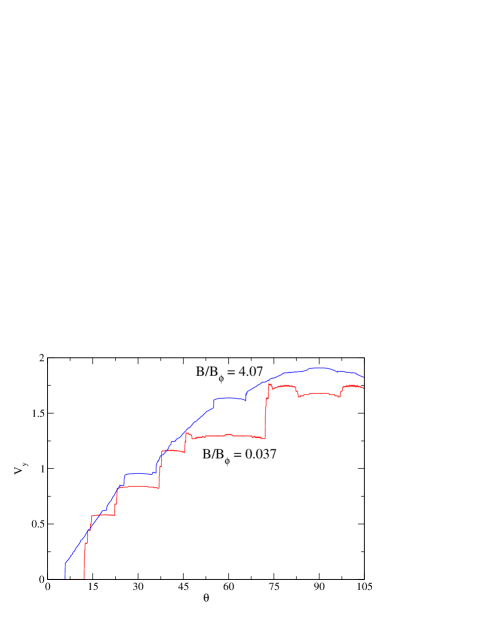
At low vortex densities the system acts in the single particle limit and the vortices jump from one locking step to another with no unlocked regions between the steps. At higher densities, unlocked regions of disordered collective flow appear between the steps. A comparison between the low and high density behaviour appears in figure 8, which shows versus for and . In the unlocked regions, the vortex-vortex interactions are strong enough to permit the vortices to form a triangular lattice. It is the strong vortex-vortex interactions that destroy the higher order steps at the higher densities.
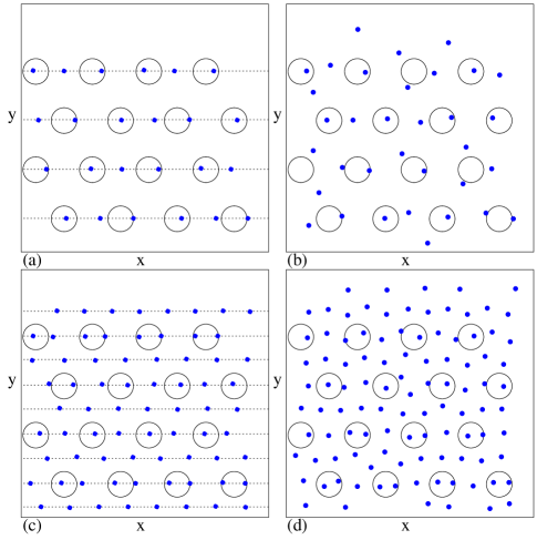
In studies of vortex matter confined to narrow channels, the critical current or depinning force oscillates as a function of vortex density depending on how many rows of vortices can fit inside the channel [48, 49]. More recent studies of two-dimensional periodic pinning arrays show a dynamical commensuration effect that occurs in the limit where the vortices at the pinning sites remain pinned but the number of interstitial vortices flowing through interstitial regions increases with [37]. In this case the transverse depinning force exhibits local minima and maxima as a function of . At each local maximum, an integer number of vortex rows fit between the pinned vortices and the vortex trajectories are highly ordered. As long as this integer number of rows can be maintained, remains high, but eventually a buckling instability occurs and produces a disordered moving vortex structure which has a low . As increases further, a new ordered vortex state with rows of moving vortices forms and increases again. The oscillations in shown in figure 6 are very similar in nature to this effect; however, a key difference is that there are no pinned vortices in the rotating drive system. Along the step, all of the vortices are moving and some of the vortices are sliding over rows of pinning sites. The remaining vortices slide through the interstitial regions between rows of pinning sites. When an integer number of interstitial sliding rows fits between adjacent rows of vortices sliding over the pinning sites, the structure of the vortex lattice is smectic and there is a local maximum in . At other values of where an integer number of interstitial sliding rows is unable to form, the vortex lattice is more disordered and is low or zero. We illustrate this effect in figure 9 where we show the locations of the vortices and pinning sites for different values of on the step. Near the local maximum in at , figure 9(a) indicates that the vortices flow in one-dimensional channels along the pinning rows and that there are no vortices flowing in the interstitial regions between rows of pinning. At , figure 9(b) shows that the vortices are no longer aligned with the pinning rows and that some vortices are flowing through the interstitial regions. Near another local maximum in at , we show in figure 9(c) that all of the vortices are flowing in one-dimensional rows and that half of the rows pass through pinning sites while the other half of the rows pass through interstitial regions. At , near a local minimum in , figure 9(d) illustrates that the one-dimensional channel structure is lost. We expect that for even higher values of , additional local maxima in will occur for fields at which two, three, or higher integer numbers of rows of vortices can be accommodated in the interstitial regions. This same mechanism of the formation of integer numbers of ordered one-dimensional flowing channels also produces the local minima and maxima in the transverse critical force found for quasicrystalline pinning arrays in [32]. In the quasicrystalline system, the existence of orientational order is sufficient to permit the formation of ordered channels of flow, and translational order is not required. Systems with random pinning substrates exhibit no oscillations in as a function of field since these substrates lack long-range orientational order. We thus expect that any periodic or quasiperiodic pinning substrate which has orientational order will produce oscillations in the transverse depinning force as a function of particle density. Similar oscillations of the widths of the higher order locking steps with increasing field should also occur; however, since the spacing between the one-dimensional channels of particles flowing along the pinning sites will vary from step to step, the particle densities at which the local minima or maxima in step width occur may be different than the densities at which maxima and minima of for the step occur.
5 Square Pinning Array
The same general behaviour found for the triangular pinning array also occurs for vortices moving over square pinning arrays. In figure 10(a) we plot versus drive angle for a sample containing a square pinning array with for , 1.5, and . In the square array, locking steps appear when with and integers, and in the figure we highlight steps with = (0,1), (1,3), (1,2), (1,1), (2,1), (3,1), and (1,0). The most prominent steps fall at (0,1) for and (1,1) for . At , many of the higher order steps are very small or or missing and the (1,1) step is much reduced in size while the (1,2) and (2,1) steps remain prominent. In figure 10(b) we plot the width of the (0,1) step vs . The behaviour of is very similar to that shown for the triangular pinning array in figure 6. For the square array, local minima in appear at , 2.0, and . At the local maxima of , we find the same one-dimensional channeling effects described in the previous section for the triangular pinning arrays. The structure of the vortex lattice on the steps in the square pinning array system is also similar to that found for the triangular arrays, as illustrated in figure 11. For example, a smectic structure appears at on the (0,1) step, shown in figure 11(a,b). One distinction is that the square pinning array system shows a much larger number of locking steps where the vortices form a square moving lattice structure, such as that illustrated for the (1,2) step at in figure 11(c,d).
6 Substrate Strength and Different Locking Regimes
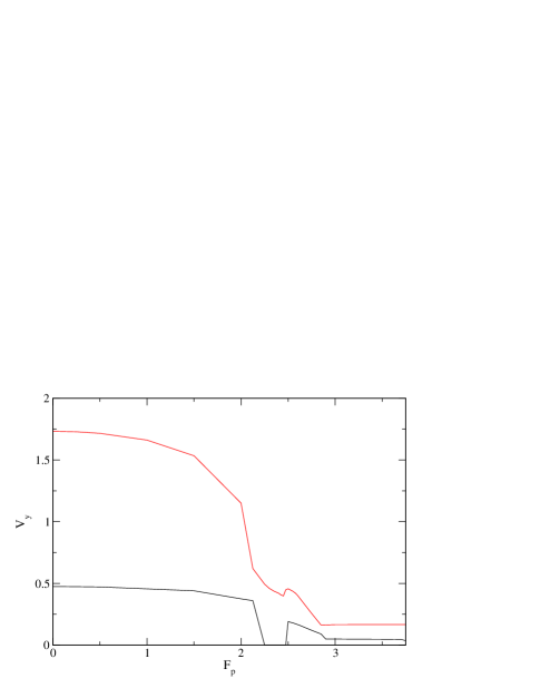
We next consider the effect of substrate strength on the locking regimes for a system with a triangular pinning lattice at fixed . In figure 12 we plot versus for samples with , 0.5, 1.0, and 1.5. The step widths grow with increasing . A similar effect was observed for locking on square pinning arrays in previous work [1]. As the substrate strength becomes very large, we observe a new phenomenon where the locking effects become reduced. The plot of versus for in figure 13(a) shows that although the and the locking steps are present, all of the remaining steps are gone and are replaced by a strongly fluctuating regime. Some directional guidance effects still occur within this strongly fluctuating regime, as shown by the dip in appearing at and the shoulder feature near . In the non-step regions, the flow is strongly disordered. The trajectories of the particles do not fall into ordered channels but mix strongly, and vortices become pinned and depinned at random. Although ordered flow occurs along the and steps, it differs from the ordered flow found at the lower pinning forces shown in figure 12. We find that collective effects between the particles begin to dominate the behaviour once . In a system with a vortex density low enough to fall into the single particle behaviour limit, all of the vortices are immobilized for since the pinning strength exceeds the magnitude of the driving force, . For all of the values of shown in figure 12, we have and there are no pinned vortices; instead, all of the vortices flow along or between the pinning sites. On the locking steps at , motion occurs in the form of a pulse of depinned vortices which passes through a background of pinned vortices. Each vortex spends part of the time pinned and part of the time moving, and there are always some pinned vortices present, but the identity of the the pinned vortices is constantly changing. This is why along the step for is nearly a factor of 3 lower than along the (1,0) step for , where the vortices move continuously and are never pinned. A similar soliton or incommensurate flow of vortices along rows of pinning sites has been observed previously for vortices driven along a single principle axis of periodic pinning arrays [34]. Additionally, a transition from a higher velocity random or turbulent type of vortex flow to a lower velocity flow state with smaller fluctuations was also observed in Ref. [34], a feature which resembles the transition in and out of the (1,0) step in figure 13(a). We find a very pronounced jump up in at the end of each of the two locking steps which is correlated with a sudden jump in (not shown).
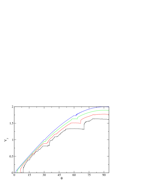
Figure 13(b) shows that for , all the steps are gone and the flow is always in the strongly fluctuating regime. The former steps are replaced with local minima in at the angles where the , , , and locking steps would have occured, indicating that there is still a guidance effect from the substrate but not complete locking of the vortex motion. At in figure 13(c), the (0,0), (1,1), and locking steps reappear and a dip in persists at where the (1,0) step would have been. For , figure 13(d) shows that the (0,1), (1,2), (1,1), (2,1), and steps are now all restored, while between the steps the flow enters a rapidly fluctuating phase in which is significantly enhanced. In figure 13(d), along a given locking step is not constant but has a curved shape and decreases noticeably just before the end of each step. The vortex flow on the steps occurs in the form of an incommensurate or solitonlike pulse of depinned vortices which passes through a background of pinned vortices. For , the vortices transition directly from one locking step to the next locking step and there are no longer regions of random flow between the steps, as illustrated in figure 14 for a sample with that exhibits a rich variety of locking steps. As increases further, the versus curves retain the shape shown in figure 14 with small shifts in the steps until , at which point all the vortices become pinned for all .


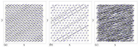

To demonstrate the differences in the flow for samples with strong and weak pinning, in figure 15(a,b) we plot the vortex trajectories on the (1,1) locking step at over a fixed time interval. For , figure 15(a) shows that all the vortices move along one-dimensional paths oriented along the driving direction. For in figure 15(b), only a portion of the vortices move in one-dimensional paths along the pinning rows while the remaining vortices are pinned. Figure 15(c) shows that in the sample at , a fluctuating flow phase occurs and there is no longer any one-dimensional channeling of the vortex motion. For samples with strong substrates, along the locking steps the vortices generally exhibit a triangular structure since a large portion of the vortices are trapped by the pinning sites, so the large scale structural transitions found for samples with weak substrates are lost. By conducting a series of simulations for varied we map the transition between the strong and weak substrate regimes, as shown in figure 16 where we highlight the widths of the (0,1), (1,1), (1,0), and locking steps. The (0,1) step increases in width with increasing up to , after which the step vanishes. This denotes the transition from the weak pinning locking regime to the random fluctuating phase. For the (0,1) step reappears in the strong pinning regime and its width saturates for . The higher order steps also show similar features with the step widths diminishing to zero at and the steps vanishing close to . There are also many other higher order steps not shown in figure 16 which in general have similar behaviour.


In figure 17 we show that the crossover from the weak pinning to the strong pinning regime can also be identified by measuring versus . We plot the width of the (1,0) step from figure 16 in figure 17(a), and show the corresponding in figure 17(b). At , , and generally decreases with increasing as more dislocations enter the system in the moving smectic phase until reaching at . There is then a dip in at where the step width drops to zero. For , increases with increasing until reaching when the system enters the strongly pinned regime and a large portion of the vortices become pinned in the triangular substrate, increasing the amount of sixfold ordering present. It is also possible to detect the crossover between the weak and strong pinning regimes using the average velocity in the -direction versus for a given , as shown in Figure 18(a) for and . At the values of the velocities are simply and . As increases, monotonically decreases until just above which marks the crossover to the strong pinning regime in which remains constant for increasing . The decrease in in the weak pinning regime can be fit to the functional form , where is the saturation value of the velocity in the strong pinning regime and is the critical value of the pinning force at which the system enters the strong pinning regime, identified as the value of above which becomes constant. In figure 18(b) we show this scaling with normalized by . Here the and curves collapse on each other and the solid line indicates a fit with . The behaviour of the curves varies on different sets of locking steps, so a straightforward scaling such as that shown in figure 18(b) is not always possible. For example, in figure 19 we plot versus on the step as well as for a driving angle of . In both cases decreases with increasing for . For , drops to zero within the weak pinning regime when the (0,1) step widens to include this driving angle and the vortices move in one-dimensional channels that are aligned with the axis. Near , for both driving angles passes through a local maximum when the system enters the random fluctuating flow regime. At for , the step reappears in the strong pinning regime, where remains constant. Similarly for saturates to a nearly constant value in the strong pinning regime.

We next consider the effects of changing on the behaviour in the strong pinning regime. In figure 20 we plot versus for a triangular pinning system with at , 1.48, 1.852, 2.407, 2.78, 3.148, 4.0, and . The system is pinned at all for . For all of the fillings shown in figure 20, strong locking effects occur, and the widths of some of the locking steps vary with . For the (1,0) locking step shows increased curvature and regions of negative differential conductivity appear near , , and , while there is a dome like feature on the locking step. At some values of , a series of smaller locking steps appear, but these small steps disappear for larger values of . In general, all of the smaller steps are washed out for increasing .
In figure 21 we plot the width of the (0,0) step versus for the strong pinning regime sample from figure 20. The broad features of the curve are similar to the behaviour of in the weak pinning regime that was shown in figure 6. There are several local minima and maxima in and a broad maximum in the range , as well as another local maximum near . As in the weak pinning regime, for the strong pinning regime the maxima in are not centred at integer matching fields. Unlike the weak pinning regime, however, there are no fillings at which drops to zero. We also observe sharp and narrow peaks at and , while no comparably sharp peaks in occured in the weak pinning regime. Longitudinal depinning studies performed for vortices moving over triangular pinning arrays have demonstrated enhanced pinning at fractional matching fields such as , , and higher order multiples where the vortices can form submatching configurations with triangular ordering [50]. The vortex flow on the (0,0) step for occurs via the same flow of incommensurations along the pinning sites that was illustrated in figure 15(b), and the peaks in at and correspond to fillings at which the moving incommensurations can form a triangular ordering. We expect that for a square pinning lattice in the strong pinning regime, peaks in the width of the first step would occur at , , and . In figure 21 for , a portion of the vortices begin to flow in the interstitial regions, which may prevent the formation of higher order fractional matching peaks.
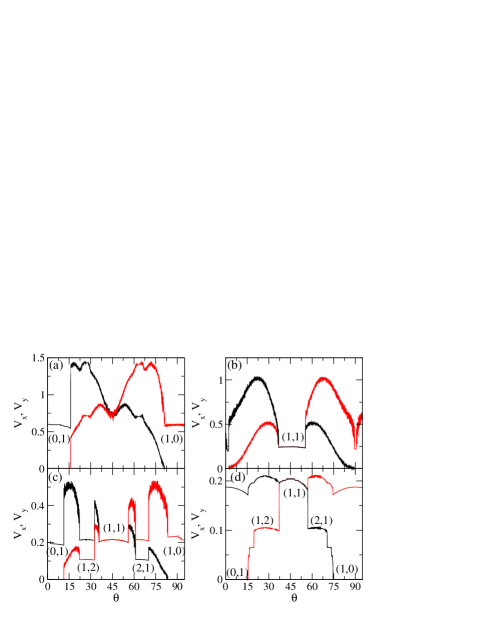
We find the same transition from a weak pinning regime to a strong pinning regime for square pinning arrays. In figure 22(a) we plot and versus for a sample with square pinning at and , where locking steps and randomly fluctuating phases appear. On the (0,1) and (1,0) locking steps, the vortices all flow along rows or columns of pinning sites. At where the (1,1) step should appear, we find no step but instead both and pass through a local minimum. There are also some weak locking shoulder features in and near and . Even though reaches its maximum cycle value at , sits in a local minimum at this driving angle. For shown in figure 22(b), the and steps have almost completely disappeared; however, there is now a clear (1,1) locking step. At , figure 22(c) indicates that locking steps emerge at (0,1), (1,2), (1,1), (2,1), and , with large fluctuating regions falling between adjacent locking steps. For the system enters the strong pinning regime and the random fluctuating regions disappear, as shown in figure 22(d) for . Here, is higher on the (2,1) step than on the (1,0) step even though no random fluctuating region separates the two steps. The length of the moving incommensurations on the step is slightly larger than the length of the moving incommensurations along the step, leading to the higher value of for the (2,1) step.
7 Colloidal Particles Moving Over Triangular and Square substrates
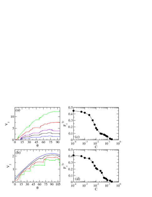
Another question is how general the results we have obtained for the vortex system are for other types of particle interactions, particularly colloidal particles where there is currently considerable interest in kinetic locking effects. We have tested all of the major predictions for the vortex system on square and triangular pinning lattices for colloidal particles interacting with a screened Yukawa potential. In figure 23(a) we plot vs for colloidal particles on a square pinning array of strength for varied colloid densities of , 0.778, 1.125, 1.82, and . The colloid-colloid interaction coefficient is . Here we find the same locking step features observed for the vortex system, with the same oscillations in the width of the first and higher order steps. At the width of the first step drops to zero, but the first step reappears at , similar to what was observed for the vortex system. We also find the same behaviours for colloids on triangular pinning arrays. One quantity that can be varied in the colloidal system but not in the vortex system is the particle-particle interaction strength. This can be achieved either by increasing the effective charge of the colloids or by changing the screening length while keeping the strength of the substrate fixed. In figure 23(b) we plot versus for colloids on a triangular pinning lattice at fixed and with , 0.01, 0.05, and . As increases, the widths of the locking steps decrease since the colloid lattice becomes stiffer and is less able to distort to adjust to the pinning.
Figure 23(d) shows the width of the first locking step as given by the value of the component of the driving force at the end of the step as a function of for colloids on a triangular pinning lattice from the system in figure 23(b). As increases, gradually decreases to zero. There is no clear transition between weak and strong pinning regimes when is varied, unlike the transition found when was varied for the vortex system. This is because our choice of fixed falls below the driving amplitude of , so all the colloids are moving even when the particle-particle interaction strength is negligible. In order to observe the strong pinning regime discussed earlier, it is necessary for a portion of the particles to be pinned and for the motion to occur in the form of depinned incommensurations which pass through the system. In figure 23(c) we plot the width of the first locking step versus for colloids on a square pinning array with the same parameters used in figure 23(a), indicating that the same behaviour found for colloids on a triangular pinning lattice also occurs for colloids on a square pinning lattice.
8 Summary
In summary, we have investigated the collective ordering and disordering effects on directional locking for particles such as vortices and colloids moving over triangular and square substrate arrays. We identify several different regimes of collective behaviour as a function of the substrate strength and of the ratio of particle density to substrate minima density. For weak substrates, at certain driving angles all the particles flow along one-dimensional channels through the pinning sites, generating a series of constant velocity steps on which the motion remains locked to a certain direction over a range of driving angles. As the pinning strength decreases, the width of the locking steps decreases and larger ranges of driving angle are occupied by nonlocking regions in which the particle-particle interactions dominate and a triangular particle lattice forms. On the locking steps for triangular substrate arrays, we find that a rich variety of different types of moving lattices form, including moving smectic, square, anisotropic disordered, and distorted triangular lattice structures. The most prominent locking steps are associated with smectic type particle orderings. In the weak substrate regime, we observe that the widths of the steps including the initial transverse depinning barrier pass through local minima and maxima as a function of the ratio of particle density to substrate minima density. In contrast to the longitudinal depinning threshold for periodic substrates, which shows peaks at commensurate fields, the local maxima for the width of the first locking step are not correlated with the two-dimensional periodicity of the pinning array but are instead related to a dynamical commensuration effect caused by the formation of one-dimensional channels of moving particles. A local maximum in the width of the first locking step occurs when integer numbers of rows of moving vortices can fit in the interstitial areas between the pinning sites. For fillings at which the moving rows are unable to fit without buckling, the particle structure becomes disordered and the width of the first locking step is small or zero. As a function of substrate strength for fixed particle density, we identify two distinct locking regimes: a weak pinning regime where all the particles flow along the pinning sites, and a strong pinning regime where the flow occurs by means of an incommensuration or a pulse passing through a background of pinned particles. Between these two regimes the locking steps are lost and are replaced by a strongly fluctuating regime where the particle motion does not lock to a particular direction. For a fixed driving angle, the average particle velocity drops sharply at the crossover between these two regimes, and the velocity saturates to a plateau value in the strong substrate limit. In the strong substrate regime the width of the first step displays commensurate peaks when the number of particles is a fractional matching ratio of the number of substrate minima, in addition to showing peaks at the incommensurate fields as in the weak pinning regime. We expect these effects to be relevant to a wide class of collectively interacting particles moving over periodic substrates, such as vortices in type II superconductors, colloids, electron crystals, and other soft matter systems.
9 Acknowledgments
This work was supported by the U.S. Department of Energy under Contract No. W-7405-ENG-36.
References
References
- [1] Reichhardt C and Nori F 1999 Phys. Rev. Lett. 82 414
- [2] Wiersig J and Ahn K-H 2001 Phys. Rev. Lett. 87 026803
- [3] Korda P T, Taylor M B and Grier D G 2002 Phys. Rev. Lett. 89 128301
- [4] MacDonald M P, Spalding G C and Dholakia K 2003 Nature (London) 426 421
- [5] Lacasta A M, Sancho J M, Romero A H and Lindenberg K 2005 Phys. Rev. Lett. 94 160601 Gleeson J P, Sancho J M, Lacasta A M and Lindenberg K 2006 Phys. Rev. E 73 041102 Sancho J M and Lacasta A M 2010 Eur. Phys. J. Special Topics 187 49
- [6] Reichhardt C and Olson Reichhardt C J 2004 Phys. Rev. E 69 041405
- [7] Gopinathan A and Grier D G 2004 Phys. Rev. Lett. 92 130602
- [8] Pelton M, Ladavac K and Grier D G 2004 Phys. Rev. E 70 031108 Roichman Y, Wong V and Grier D G 2007 Phys. Rev. E 75 011407
- [9] Long B R, Heller M, Beech J P, Linke H, Bruus H and Tegenfeldt J O 2008 Phys. Rev. E 78 046304
- [10] Speer D, Eichhorn R and Reimann P 2010 Phys. Rev. Lett. 105 090602
- [11] Speer D, Eichhorn R and Reimann P 2009 Phys. Rev. Lett. 102 124101
- [12] Frechette J and Drazer G 2009 J. Fluid Mech. 627 379
- [13] Balvin M, Sohn E, Iracki T, Drazer G and Frechette J 2009 Phys. Rev. Lett. 103 078301
- [14] Herrmann J, Karweit M and Drazer G 2009 Phys. Rev. E 79 061404
- [15] Xiao K and Grier D G 2010 Phys. Rev. Lett. 104 028302 Xiao K and Grier D G 2010 Phys. Rev. E 82 051407
- [16] Khoury M, Lacasta A M, Sancho J M, Romero A H and Lindenberg K 2008 Phys. Rev. B 78 155433
- [17] Loutherback K, Puchalla J, Austin R H and Sturm J C 2009 Phys. Rev. Lett. 102 045301 Loutherback K, Chou K S, Newman J, Puchalla J, Austin R H and Sturm J C 2010 Microfluidics Nanofluidics 9 1143
- [18] Huang L R, Cox E C, Austin R H and Sturm J C 2004 Science 304 987
- [19] Reichhardt C, Olson C J and Hastings M B 2002 Phys. Rev. Lett. 89 024101 Reichhardt C and Olson Reichhardt C J 2003 Phys. Rev. E 68 046102
- [20] Tierno P, Johansen T H and Fischer T M 2007 Phys. Rev. Lett. 99 038303 Soba A, Tierno P, Fischer T M and Sagues F 2008 Phys. Rev. E 77 060401(R)
- [21] Koplik J and Drazer G 2010 Phys. Fluids 22 052005
- [22] Marconi V I, Candia S, Balenzuela P, Pastoriza H, Domínguez D and Martinoli P 2000 Phys. Rev. B 62 4096
- [23] Carneiro G 2002 Phys. Rev. B 66 054523
- [24] Surdeanu R, Wijngaarden R J, Griessen R, Einfeld J and Wördenweber R 2001 Europhys. Lett. 54 682
- [25] Silhanek A V, Van Look L, Raedts S, Jonckeere R and Moshchalkov V V 2003 Phys. Rev. B 68, 214504
- [26] Villegas J E, Gonzalez E M, Montero M I, Schuller I K and Vicent J L 2003 Phys. Rev. B 68 224504
- [27] Giamarchi T and Le Doussal P 1996 Phys. Rev. Lett. 76 3408
- [28] Reichhardt C and Olson Reichhardt C J 2007 Phys. Rev. B 76 214305
- [29] Achim C V, Ramos J A P, Karttunen M, Elder K R, Granato E, Ala-Nissila T and Ying S C 2009 Phys. Rev. E 79 011606
- [30] Yang Y, Duan W-S, Chen J-M, Yang L, Tekić J, Shao Z-G and Wang C-L 2010 Phys. Rev. E 82 051119
- [31] Granato E and Ying S C 2000 Phys. Rev. Lett. 85 5368
- [32] Reichhardt C and Olson Reichhardt C J 2011 Phys. Rev. Lett. 106 060603
- [33] Harada K, Kamimura O, Kasai H, Matsuda T, Tonomura A and Moshchalkov V V 1996 Science 274 1167
- [34] Reichhardt C, Olson C J and Nori F 1998 Phys. Rev. B 57 7937
- [35] Berdiyorov G R, Milosevic M V and Peeters F M 2006 Phys Rev. B 74 174512
- [36] Reichhardt C, Olson C J and Nori F 1997 Phys. Rev. Lett. 78 2648 Reichhardt C, Zimányi G T and Grønbech-Jensen N 2001 Phys. Rev. B 64 014501
- [37] Reichhardt C and Olson Reichhardt C J 2008 Phys. Rev. B 78 180507(R)
- [38] Moon K, Scalettar R T and Zimányi G T 1996 Phys. Rev. Lett. 77 2778 Olson C J, Reichhardt C and Nori F 1998 Phys. Rev. Lett. 81 3757 Kolton A B, Domínguez D and Grønbech-Jensen N 1999 Phys. Rev. Lett. 83 3061
- [39] Le Doussal P and Giamarchi T 1998 Phys. Rev. B 57 11356 Balents L, Marchetti M C and Radzihovsky L 1998 Phys. Rev. B 57 7705
- [40] Pardo F, de la Cruz F, Gammel P L, Bucher E and Bishop D J 1998 Nature (London) 396 348
- [41] Fangohr H, Cox S J and de Groot P A J 2001 Phys. Rev. B 64 064505
- [42] Fangohr H, de Groot P A J and Cox S J 2001 Phys. Rev. B 63 064501
- [43] Reichhardt C and Zimanyi G T 2000 Phys. Rev. B 61 14354
- [44] Carneiro G 2002 Phys. Rev. B 66 054523
- [45] Gutierrez J, Silhanek A V, Van de Vondel J, Gillijins W and Moshchalkov V V 2009 Phys. Rev. B 80 140514(R) Avci S, Xiao Z L, Hua J, Imre A, Divan R, Pearson J, Welp U, Kwok W K and Crabtree G W 2010 Appl. Phys. Lett. 97 042511
- [46] Olson Reichhardt C J and Reichhardt C 2009 EPL 88 47004
- [47] Fiory A T, Hebard A F and Somekh S 1978 Appl. Phys. Lett. 32 73 Baert M, Metlushko V V, Jonckheere R, Moshchalkov V V and Bruynseraede Y 1995 Phys. Rev. Lett. 74 3269 Martín J I, Vélez M, Nogués J and Schuller I K 2002 Phys. Rev. Lett. 79 1929 Welp U, Xiao Z L, Jiang J S, Vlasko-Vlasov V K, Bader S D, Crabtree G W, Liang J, Chik H and Xu J M 2002 Phys. Rev. B 66 212507
- [48] Anders S, Smith A W, Besseling R, Kes P H and Jaeger H M 2000 Phys. Rev. B 62 15195 Besseling R, Kes P H, Dröse T and Vinokur V M 2005 New J. Phys. 7 71
- [49] Karapetrov G, Fedor J, Iavarone M, Rosenmann D and Kwok W K 2005 Phys. Rev. Lett. 95 167002 (2005).
- [50] Reichhardt C and Grønbech-Jensen N 2001 Phys. Rev. B 63 054510 Ooi S, Mochiku T and Hirata K 2009 J. Phys.: Conf. Ser. 150 052203