Thermal heat radiation, near-field energy density and near-field radiative heat transfer of coated materials
Abstract
We investigate the thermal radiation and thermal near-field energy density of a metal-coated semi-infinite body for different substrates. We show that the surface polariton coupling within the metal coating leads to an enhancement of the TM-mode part of the thermal near-field energy density when a polar substrate is used. In this case the result obtained for a free standing metal film is retrieved. In contrast, in the case of a metal substrate there is no enhancement in the TM-mode part, as can also be explained within the framework of surface plasmon coupling within the coating. Finally, we discuss the influence of the enhanced thermal energy density on the near-field radiative heat transfer between a simple semi-infinite and a coated semi-infinite body for different material combinations.
pacs:
44.40.+a, 78.66.-w, 05.40.-a, 41.20.JbI Introduction
The fluctuating electrodynamic near field close to the surface of dielectric bodies due to thermal and quantum fluctuations inside that bodies has come to the fore in the last decade. The growing interest of researchers in the investigation of fluctuating near fields is accompanied by manifold new possibilities to measure the interesting properties of such thermal near fields ShchegrovEtAl00 ; CarminatiGreffet99 ; C.HenkelEtAl2000 ; J.J.GreffetEtAl2002 ; J.J.GreffetEtAl2003 ; F.MarquierEtAl2004 ; K.JoulainEtAl2005 , which have been developed in the last decade. For example, two of these techniques are the thermal radiation scanning tunneling microscopy Y.DeWileEtAl2006 and the usage of Bose-Einstein condensates J.M.ObrechtEtAl2007 . Moreover, near field scanning thermal microscopy KittelEtAl05 (NSThM) is a new possibility to measure the radiative heat transfer, which is itself related to the properties of the fluctuating near field Dorofeyev98 ; MuletEtAl01 ; KittelEtAl05 between dielectric bodies PolderVanHove71 . From the experimental point of view it should also be helpful to study the near field of coated materials.
Not only the significance of the fluctuating near field in scanning probe techniques or nanotechnological applications makes a theoretical investigation necessary and useful. The electrodynamic near field is also of great theoretical interest, because it shows new and unexpected physical properties. For example, it has been shown in recent publications CarminatiGreffet99 that coherent quasi-monochromatic evanescent waves can exist in the thermal near field, although the latter is generated by fluctuating thermal sources. In order to study near-field effects one may calculate different physical quantities such as the cross-correlation tensor CarminatiGreffet99 , the local density of states (LDOS) JoulainEtAl03 or the spectral energy density ShchegrovEtAl00 in the vicinity of the dielectric body, where this body is usually assumed to be a semi-infinite medium.

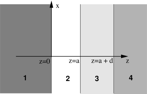
In this paper we will study how a coating influences the thermal electrodynamical near field of a semi-infinite substrate (see fig. 1). For that reason we calculate the energy density above the coated body. We will show that an effect predicted for a free standing metallic film Biehs2007 can be retrieved by using a polar material as substrate, whereas for a metal substrate the thermal near-field energy density changes dramatically. Both cases are discussed and understood with the help of surface plasmon coupling within the coating. Furthermore we investigate how the coating on different substrates influences the near-field radiative heat transfer.
The near-field radiative heat transfer was already disussed in such a slab configuration for polar materials A.NarayanaswamyC.Chen2003 for an application in thermophotovoltaics and briefly for metal substrates coated with different metals A.I.VolokitinB.N.J.Persson2001 . Here we explicitly calculate the near-field radiative heat transfer between a semi-infinite and a coated semi-infinite body, showing in detail that the physical mechanisms leading to different energy densities will leave their imprints in the near-field radiative heat transfer. With this information at hand it could for example be possible to give a better understanding of the signal measured with a NSThM, and to clarify the question whether that signal can be interpreted within a dipole-model Dorofeyev98 ; MuletEtAl01 or whether it can be modelled as the heat transfer between a semi-infinite and a coated semi-infinite body. Furthermore, the results derived in this and the preceding paper Biehs2007 can also serve as a basis for the investigation of near-field effects for coated materials, which are often used in experimental setups.
This paper is a direct follow-up of reference Biehs2007 , so we refer the reader to that paper for a brief discussion of Rytov’s fluctuational electrodynamics RytovEtAl89 . When considering the geometry given in fig. 1, it is in principle necessary to construct the dyadic Green’s function with observation point located in the regime , and with sources within the coating or the substrate, respectively. Since we already determined the dielectric Green’s function for a dielectric film, as corresponding to the coating, in all details Biehs2007 , the dyadic Green’s function with source currents within the coating can directly be taken from that reference. The dyadic Green’s function with sources within the substrate can be constructed in a straightforward way, so we present here only the results and refer the interested reader to Biehs2007 and ChenToTai71 , respectively. For convenience we use the same notation as in our preceding paper Biehs2007 , and for comparability we use again for numerical computations the Drude model for metals and the Reststrahlen formula for polar materials with material parameters taken from AshcroftMermin76 ; S.Adachi2004 .
This paper is organized in the following way: In section II we briefly discuss the thermal radiation of a coated material. In section III we study the thermal near field of the coated material for different coatings and substrates and show in section IV how the observed effects can be interpreted with the surface plasmon polariton coupling inside the coating. Finally, in the last section we calculate the near-field radiative heat transfer and discuss the influence of a metal coating.
II Thermal radiation
In this paper we are mainly interested in the evanescent near field of the coated semi-infinite body, but for the sake of completeness we also report the results for the radiative part. In order to derive the thermal radiation of the coated semi-infinite body we calculate the averaged -component of the Poynting vector outside the layered system in fig. 1, which is assumed to be in local thermal equilibrium at temperature , setting . Taking fluctuating source currents inside the bulk medium (the substrate) with permittivity and inside the coating with permittivity , which contribute additively to the Poynting vector outside the layered system, we get after a lengthy but straightforward calculation
| (1) |
The transmission coefficents are given as the sum of the bulk and coating transmission coefficients, , for TM- and TE-polarization ( and ), respectively. The transmission coefficients for the bulk contribution are given by
| (2) |
with for and
| (3) |
The coefficients and are defined as
| (4) | ||||
| (5) | ||||
| (6) | ||||
| (7) |
The transmission coefficients for the coating have already been calculated in Biehs2007 and can be stated as
| (8) |
with
| (9) | ||||
| (10) |
where we have used the notation . Even though the transmission coefficients, which are rather complicated, could be reformulated in term of Fresnel reflection coefficients J.D.Jackson1999 , we will not perfom this procedure here, because in that case we get different forms of transmission coefficients for the propagating and evanescent modes (cf. Biehs2007 ), i.e., we get four equations instead of the two given in (2) and (8), thus unnecessarily inflating the formalism. But it should be kept in mind that the transmission coefficients, which can be stated with one equation for the propagating part with and the evanescent part with , behave in a quite different manner for propagating and evanescent modes, respectively. This is a consequence of the fact that is purely real for propagating modes or purely imaginary for evanescent modes, . Therefore, the evanescent component does not contribute to the expression for the Poynting vector (1), i.e., the Poynting vector covers information on the propagating modes only.


Before we present numerical results for the Poynting vector, we specify the limiting values of the transmission coefficients for the propagating modes for different layer thickness , considering the two cases and , i.e., layers much thicker or thinner than the skin depth of the coating material, given by
| (11) |
For thin coatings with the transmission coefficients go linearly with thickness to zero (cf. Biehs2007 ), whereas the transmission coefficents of the bulk converge to the transmission coeffient of a semi-infinite body PolderVanHove71 with permittivity , i.e.,
| (12) |
In contrast, for thick coatings with the transmission coefficents of the bulk contributions go to zero and the transmission coefficients of the coating converge to the transmission coeffient of a semi-infinite body PolderVanHove71 with permittivity , which can be derived from eq. (12) by exchanging the index 1 with 2.
Therefore, the thermal radiation of a coated body given by propagating modes only and being independent of (because for propagating modes), has different values for different thicknesses of the coating. In the limit that the coating is very thick, i.e., , the radiation is that of a half-space filled with the coating material only. In the other limit of very thin coating, i.e. , the radiation is that of a half-space filled entirely with the bulk material. In general, the value of the Poynting vector always falls between these two extremes. Thus it seems that the thermal radiation maximum found for free standing metallic films of a certain thickness Biehs2007 cannot be observed for coated materials. This is illustrated in the left panel of fig. (2), where there is a maximum in the contribution of the coating, but this is overlayed by the bulk contribution.
III Thermal near field
Next, we discuss the non-radiative part of the fluctuating near field in the vicinity of the coated substrate. To this end, we investigate the energy density in the distance from the coated body, which can be written as
| (13) |
with for propagating modes with and for evanescent modes with . Here the factor appearing in the transmission coefficients (2) and (8) is canceled out by the denominator in eq. (13), so that the energy density contains information about the evanescent thermal near field. Due to these evanescent modes the expression for the energy density becomes dependent on the distance from the layered system, although the contribution of the propagating modes is again independent of the observation distance .

Taking the limits for thin and thick coatings is in this case not easy, because for the evanescent modes the transmission coefficients of the coating contain expressions depending on in the nominator and denominator which compete with each other, in analogy to the behaviour discussed in ref. Biehs2007 for a single thin dielectric layer. In contrast, the limit of the transmission coefficients for a thin coating with reduces for both propagating and evanescent modes to the expression (12) and vanishes for thick coatings, .

In the evanescent-mode regime the energy density depends on or, more precisely, on . From this fact and the form of the transmission coefficients given in eq. (8) it appears reasonable to discuss the cases of thin and thick coatings, i.e., and , in the regions and separately. As follows from ref. Biehs2007 , in the region the transmission coefficients take the same form as those for a half-space filled entirely with the coating material. It can be shown that for the bulk contribution becomes negligible. This is a reasonable result, because the evanescent waves with the lateral wave vector are damped at a length scale above the layered system. Therefore for the near field is dominated by evanescent waves with , which do not carry information about the restriction due to the finite layer thickness . From that it seems to be clear that for one receives a result which coincides with that for a bulk made up of the coating material, i.e., with the permittivity .


For and the situation is more complex, as far as TM modes are concerned. The TM-mode contribution to the thermal energy density given by the coating is in that region given by Biehs2007
| (14) |
where and are the usual Fresnel reflection coefficients J.D.Jackson1999 for the interfaces at and , respectively, and . Through these reflection coefficients, the energy density depends on the properties of bulk and coating material. Let us restrict the following discussion to metal coatings, so that . Now the energy density contribution of the coating solely depends on the choice of bulk material. If we choose as bulk material the vacuum or a polar material, i.e., or , then the expression for the energy density reduces to
| (15) |
For a metal film or a coated polar material, respectively, we get a -dependence of the energy density, as discussed in Biehs2007 . (For a metal coating obeying the Hagens-Rubens approximation the power laws derived in Biehs2007 also give reasonable approximations for a polar substrate.) In contrast, if we take a second metal as bulk material, then the reflection coefficients between these two metals should be small, so we can approximate the denominator in eq. (14) by 1. As a consequence we find a -dependence of the energy density for the TM-modes for coated metals. Therefore, the -dependence of provided by a half-space consisting solely of the coating material for changes to a - or -dependence for when considering a polar or metal bulk with a metal coating. In fig. 3 this splitting is shown for a Bi-coating of different thicknesses on a GaN bulk and an Al bulk, respectively. It is interesting to see that the contribution of the coating material to the energy density for polar bulk materials becomes greater than its bulk value for distances , similar to what has been discussed for thin metall films in ref. Biehs2007 .

Such a splitting can also be observed for the TE-mode part of the energy density contribution of the coating material for distances , as shown in fig. 4. But in contrast to the energy density of the coating material does never rise over its bulk value. From the numerical result displayed in fig. 4 one can infer that for a coated polar bulk material again has a -dependence for , whereas for coated metals there seems to be no well-developed power law.
Now let us study the interplay of the contributions of the bulk or substrate and that of the coating to the thermal energy density for . From the discussion above it follows that for it is always which dominates the total energy density, with the value of coinciding with its half-space value, i.e., being independent of the coating thickness . For distances it is a priori not clear whether the bulk or the coating contribution dominates the energy density. However, one may expect for a polar bulk material and a metal coating that the bulk contribution does not play an important role because , whereas for a metal bulk is small, so that waves generated by fluctuating source currents in the bulk medium can propagate into and through the coating and therefore contribute to the energy density in a much more significant way at distances . In fig. 5 the numerical plots for Al/Bi and GaN/Bi systems confirm this expectation.
Before finishing the discussion of the energy density, we give in figs. 6 and 7 two further numerically computed plots of and for a Bi-coating on different bulk materials. One sees that the - and -power laws of derived above leave their imprints in the TM-mode part of the total energy density. For the TE-mode part of the energy density one has to distinguish between a metal-metal system and a polar material-metal system, because for a metal-metal system at the bulk contributions dominate the energy density, but for a polar bulk material this region is dominated by the contribution of the metal coating only.

IV Surface plasmon coupling
The rise in the TM-mode part of the energy density for a polar substrate coated with a metal can be explained in terms of the low-frequency surface plasmon polariton resonance within the coating. In the given geometry (see fig. 1) the surface modes are given by the zeros of the function KliewerFuchs67 ; J.J.BurkeEtAl1986 ; H.Raether1980
| (16) |
with . This function coincides with the denominator of (cf. in eq. (8)). For a non-magnetic material these surface modes are purely TM-polarized and do exist for materials with a negative permittivity only H.Raether1980 . For a polar substrate or bulk material with a metal coating the Fresnel coefficient can be approximated by for all relevant frequencies. Within this rough approximation the dispersion relation in eq. (16) coincides with the dispersion relation of a free standing metal film surrounded by a vacuum only. Therefore the conclusions drawn for a free standing metal film Biehs2007 can be applied to the metal-coated polar substrate.
It follows H.Raether1980 ; Biehs2007 that for coatings thinner than the skin depth the two degenerate surface plasmon branches with the resonance frequency split into two non-degenerate branches given by H.Raether1980
| (17) |
where for convenience the plasma model is used to describe the permittivity. As expressed by eq. (17) the resonance frequency of the high-frequency surface plasmon polariton branch goes to the plasma frequency of the coating, and the resonance frequency of the low-frequency branch goes to zero for very thin coatings, i.e., for . Due to the fact that the -integral for the energy density in eq. (13) is dominated by lateral wave vectors of the order , for the splitting of the surface plasmon branch cannot be observed, since . In this case one obtains the same energy density as in the case of an infinitely thick coating. On the other hand, for observation distances in the near field above the coated material the surface plasmon coupling leads to a splitting of the surface plasmon branches, since in this case. Therefore at these distances the resonance of the low-frequency branch will go to frequencies which are accessible thermally, leading to an increase in the thermal near-field energy density.

In fig. 8 we plot the local density of states (LDOS) defined in JoulainEtAl03 for the TM-modes only. One observes how the resonance at splits into two resonances, where the high-frequency resonance goes to of the coating and the low-frequency resonance goes straight to zero. Thus, it reaches the thermally accessible region for thin coatings and increases the LDOS in that region, and therefore also the thermal near-field energy density leading to the -power law.
For a metal substrate coated with a metallic material, the dispersion relation in eq. (16) can be approximated in the near-field region with as
| (18) |
which leads again within the plasma model to two surface plasmon polariton branches. In this case, for , the resonance frequencies of the surface plasmon polariton branches go to the plasma frequency of the coating and the surface plasmon resonance frequency for arbitrarily thin coatings. Therefore the surface plasmon polariton coupling will not lead to an increase of the LDOS in the thermally accessible region, since for real metals the plasma frequencies are much greater than the thermal frequency at . It follows that the thermal near-field energy density is unaffected by the surface plasmon coupling, leading to values below that of the semi-infinite body, and to a quite different -power law for metal substrates as previously shown in fig. 3.

In fig. 9 we plot the LDOS for the TM-modes for a Bi-coating on a Pt-substrate. The splitting of the surface plasmon resonance into two resonances is clearly visible. Here the high-frequency resonance goes to the plasma frequency of the coating and the low-frequency resonance goes to the surface plasma resonance of the substrate given by with AshcroftMermin76 .
V Thermal near-field radiation
In this last section we discuss the radiative near-field heat transfer between a semi-infinite body and a coated semi-infinite body as sketched in fig. 10. Since the calculation follows the well-established rules, we proceed directly to the result for the Poynting vector in this geometry, assuming for the material at and for the layered structure at . With , the result takes the form
| (19) |
where the symbol abbreviates the corresponding expressions for the TM-modes, and with the usual Fresnel coefficients and . In addition,
| (20) |
for TE- and TM-polarization, respectively. It can be easiliy checked that for this expression reduces to the Polder-van-Hove (PvH) result PolderVanHove71 for the near-field radiative heat transfer between two semi-infinite bodies.
It is well-known PolderVanHove71 that the radiative heat transfer between two metals described by the PvH expression A.I.VolokitinB.N.J.Persson2001 is dominated by the TE-modes, whereas the radiative heat transfer between a metal and a polar material or two polar materials, respectively, is dominated by the TM-modes giving
| (21) |
in the near-field region. Hence, the exponents of the - and -dependence of the TM- and TE-mode parts of the thermal near-field energy density of a half-space are reduced by one. It is to be expected that the radiative heat transfer between a semi-infinite body and a layered structure with a thin coating of thickness will again resemble the usual PvH expression for , since the energy density above the layered structure coincides in this case with that of a semi-infinite body consisting of the coating material only. In the opposite case, for , the radiative heat transfer should be determined by the change in the thermal near-field energy density described in the preceding section.
Furthermore one expects that when taking a metallic material for medium 1 the TE-modes of the layered structure dominate the heat transfer, so that the radiative heat transfer should behave similar to the thermal near-field energy density plotted in fig. 6. Choosing Au for medium 1 we get the near-field radiative heat transfer plotted in fig. 11. Indeed this figure fully confirms this expectation. Moreover, using a metal substrate such as Pt for medium 4, the radiative heat transfer rises over the PvH-result for a Au-Bi configuration, as is explained by the contribution of the Pt-substrate, so that in this case the radiative heat transfer in the layered structure is in prinicple, given by the PvH-result for a Au-Pt configuration.

On the other hand, choosing GaN for medium 1, we expect dominance of the TM-mode energy density depicted in fig. 7, but with reduced power laws for , i.e., the -power law should lead to a radiative heat transfer proportional to , whereas the -power law should lead to a radiative heat transfer proportional to . This is exactly what is seen in the numerical results plotted in fig. 12. Thus, it is possible to understand the near-field radiative heat transfer qualitatively from the thermal energy density of the considered materials. Even more interesting, the enhancement in the thermal near-field energy density due to surface plasmon polariton coupling in the coating material can be observed in the radiative heat transfer in a slab geometry as sketched in fig. 10.

VI Conclusions
In this paper, we have given a discussion of the thermal radiation and the thermal near-field energy density of a metal-coated substrate. It has been shown that the maximum of the thermal radiation, which is observed for free metal films at a certain thickness Biehs2007 , does not appear for coated materials, since for thin coatings the thermal radiation of the substrate hides this maximum.
On the other hand, the increase in the thermal near-field energy density of a free standing metal film Biehs2007 due to surface plasmon polariton coupling inside the metal coating has also been found for a coated substrate, when a polar material is used as substrate. For metal coatings on metal substrates such an increase does not exist. Moreover, for metallic substrates the thermal near-field energy density for observation distances and coating thickness is some orders of magnitude smaller than for a polar substrate (with the same coating), obeying a rather different power law. This difference in behaviour resulting from the interchange of the substrate material can be explained with the surface plasmon polariton coupling: For a polar substrate the thermally accessible LDOS will be enhanced due to the low-frequency surface plasmon resonance, which goes to zero frequency for arbitrarily thin coatings, whereas for a metal substrate this resonance goes to the surface plasmon resonance of the substrate for arbitrarily thin coatings and can therefore not be accessed thermally for plasma frequencies much greater than the thermal frequency.
In the last part we have shown that the differences investigated for the thermal near-field energy density of a coated material leave their imprints in the near-field radiative heat transfer between a semi-infinite body and a coated semi-infinite body. Using a metal or a polar material allows one to ’select’ the TE- or TM-mode part of the thermal near-field energy density of the coated material to dominate the radiative near-field heat transfer. Therefore, it is possible to observe the TM-mode-enhancement due to surface plasmon polariton coupling inside the coating by thermal heat transfer experiments. Due to the fact that the expressions for the near-field radiative heat transfer and the vacuum friction J.B.Pendry1997 ; A.I.VolokitinB.N.J.Persson2003 are fairly similar, the discussed effect should also be observable for vacuum friction between coated materials.
Since a polarizable particle or an atom couples to the electric field, the radiative heat transfer Dorofeyev98 ; MuletEtAl01 ; A.I.VolokitinB.N.J.Persson2002 , the spontaneous emission rate J.M.Wylie1984 ; G.W.Ford1984 ; M.S.Tomas1995 ; H.T.DungEtAl2002 near a hot body and the thermal Casimir-Polder potential P.Milonni1994 ; C.HenkelEtAl2002 ; A.I.VolokitinB.N.J.Persson2002 should be proportional to in the near field, so that the discussed enhancement of the TM-mode part of the thermal near field should also enhance the near-field radiative heat transfer between a small particle and a coated material, the spontaneous emission rate of an atom near a hot coated material, and the thermal Casimir-Polder potential, respectively. Moreover, the spin flip rate of atoms C.HenkelEtAl1999 ; P.K.Rekdal2004 above a layered structure, which is in principle proportional to , will also be changed by the use of thin coatings on appropriate substrates. Furthermore, it appears possible that the coherence of the thermal near field CarminatiGreffet99 ; C.HenkelEtAl2000 can be controlled by the use of different metal coatings, since the surface plasmon resonance frequency can be changed by the choice of the thickness of the coating. In this sense the discussion of the thermal energy density has a much broader field of application than the radiative heat transfer and the vacuum friction.
The author acknowledges support from the Studienstiftung des deutschen Volkes. Furthermore he thanks O. Huth, F. Rüting, D. Reddig, and M. Holthaus for helpful discussions and kind criticism.
References
- (1) A. V. Shchegrov, K. Joulain, R. Carminati, and J.-J. Greffet, Phys. Rev. Lett. 85, 1548 (2000).
- (2) R. Carminati and J.-J. Greffet, Phys. Rev. Lett. 82, 1660 (1999).
- (3) C. Henkel, K. Joulain, R. Carminati, and J.-J. Greffet, Opt. Comm. 186, 57 (2000)
- (4) J.-J. Greffet, R. Carminati, K. Joulain, J.-P. Mulet, S. Mainguy, and Y. Chen, Nature 416, 61 (2002)
- (5) J.-J. Greffet, R. Carminati, K. Joulain, J.-P. Mulet, C. Henkel, S. Mainguy, Y. Chen, Topics Appl. Phys. 88, 163-182 (2003)
- (6) K. Joulain, J.-P. Mulet, F. Marquier, R. Carminati, J.-J. Greffet, Surf. Science Reports 57, 59 (2005)
- (7) F. Marquier, K. Joulain, J.-P. Mulet, R. Carminati, and J.-J. Greffet, Phys. Rev. B 69, 155412 (2004)
- (8) Y. De Wilde, F. Formanek, R. Carminati, B. Galek, P.-A. Lemoine, K. Joulain, J.-P. Mulet, Y. Chen, and J.-J. Greffet, Nature 444, 740 (2006)
- (9) J.M. Obrecht, R.J. Wild, M. Antezza, L.P. Pitaevskii, S. Stringari, and E. A. Cornell, Phys. Rev. Lett. 98, 063201 (2007)
- (10) A. Kittel, W. Müller-Hirsch, J. Parisi, S.-A. Biehs, D. Reddig, and M. Holthaus, Phys. Rev. Lett. 95, 224301 (2005).
- (11) D. Polder and M. van Hove, Phys. Rev. B 4, 3303 (1971).
- (12) I. A. Dorofeyev, J. Phys. D: Appl. Phys. 31, 600 (1998).
- (13) J.-P. Mulet, K. Joulain, R. Carminati, and J.-J. Greffet, Appl. Phys. Lett. 78, 2931 (2001).
- (14) K. Joulain, R. Carminati, J.-P. Mulet, and J.-J. Greffet, Phys. Rev. B 68, 245405 (2003).
- (15) S.-A. Biehs, D. Reddig and M. Holthaus, Eur. Phys. J. B 55, 237 (2007)
- (16) A. Narayanaswamy and C. Chen, Appl. Phys. Lett. 82, 3544 (2003)
- (17) A. I. Volokitin and B. N. J. Persson, Phys. Rev. B 63, 205404 (2001)
- (18) S. M. Rytov, Y. A. Kravtsov, and V. I. Tatarskii, Principles of Statistical Radiophysics, Vol. 3 (Springer, New York, 1989).
- (19) Chen-To Tai, Dyadic Green’s Functions in Electromagnetic Theory (Intext Educational Publishers, Scranton, 1971).
- (20) N. W. Ashcroft and N. D. Mermin, Solid State Physics (Harcourt, Fort Worth, 1976).
- (21) S. Adachi, Handbook on Physical Properties of Semiconductors (Kluwer Academic Publisher, Boston, 2004)
- (22) J. D. Jackson, Classical Electrodynamics, 3rd ed. (John Wiley, New York, 1998).
- (23) K. L. Kliewer and R. Fuchs, Phys. Rev. 153, 498 (1967).
- (24) J.J. Burke and G.I. Stegeman and T. Tamir, Phys. Rev. B 33, 5186 (1986)
- (25) H. Raether, Excitation of Plasmons and Interband Transitions by Electrons (Springer-Verlag, New York, 1980)
- (26) A. I. Volokitin and B. N. J. Persson, Phys. Rev. B, 65, 115419 (2002)
- (27) J.M. Wylie and J. E. Sipe, Phys. Rev A 30, 1185 (1984)
- (28) G. W. Ford and W. H. Weber, Phys. Rep. 113, 195 (1984)
- (29) M. S. Tomaš, Phys. Rev. A 51, 2545 (1995)
- (30) H.T. Dung, L. Knöll, and D.-G. Welsch, Phys. Rev. A 65, 043813 (2002)
- (31) P. W. Milonni, The Quantum Vacuum (Academic Press, San Diego, 1994)
- (32) C. Henkel, K. Joulain, J.-P. Mulet, and J.-J. Greffet, J. Opt. A 4, 109 (2002)
- (33) C. Henkel, S. Pötting, and M. Wilkens, Appl. Phys. B 69, 379 (1999)
- (34) P. K. Rekdal, S. Scheel, P.L. Knight, and E. A. Hinds, Phys. Rev. A. 70, 013811 (2004)
- (35) J.B.Pendry, J. Phys.: Condens. Matter 9, 10301 (1997)
- (36) A.I. Volokitin and B.N.J. Persson, Phys. Rev. B 68, 155420 (2003)