The Galactic Census of High- and Medium-mass Protostars.
I. Catalogues and First Results from Mopra HCO+ Maps
Abstract
The Census of High- and Medium-mass Protostars (CHaMP) is the first large-scale, unbiased, uniform mapping survey at sub-parsec scale resolution of 90 GHz line emission from massive molecular clumps in the Milky Way. We present the first Mopra (ATNF) maps of the CHaMP survey region () in the HCO+=10 line, which is usually thought to trace gas at densities up to 1011m-3. In this paper we introduce the survey and its strategy, describe the observational and data reduction procedures, and give a complete catalogue of moment maps of the HCO+=10 emission from the ensemble of 301 massive molecular clumps. From these maps we also derive the physical parameters of the clumps, using standard molecular spectral-line analysis techniques. This analysis yields the following range of properties: integrated line intensity 1–30 K km s-1, peak line brightness 1–7 K, linewidth 1–10 km s-1, integrated line luminosity 0.5–200 K km s-1 pc2, FWHM size 0.2–2.5 pc, mean projected axial ratio 2, optical depth 0.08–2, total surface density 30–3000 M⊙ pc-2, number density 0.2–30109 m-3, mass 15–8000 M⊙, virial parameter 1–55, and total gas pressure 0.3–700 pPa. We find that the CHaMP clumps do not obey a Larson-type size-linewidth relation. Among the clumps, there exists a large population of subthermally excited, weakly-emitting (but easily detectable) dense molecular clumps, confirming the prediction of Narayanan et al. (2008). These weakly-emitting clumps comprise 95% of all massive clumps by number, and 87% of the molecular mass, in this portion of the Galaxy; their properties are distinct from the brighter massive star-forming regions that are more typically studied. If the clumps evolve by slow contraction, the 95% of fainter clumps may represent a long-lived stage of pressure-confined, gravitationally stable massive clump evolution, while the CHaMP clump population may not engage in vigorous massive star formation until the last 5% of their lifetimes. The brighter sources are smaller, denser, more highly pressurised, and closer to gravitational instability than the less bright sources. Our data suggest that massive clumps approach critical Bonnor-Ebert like states at constant density, while others’ suggest that lower-mass clumps reach such states at constant pressure. Evidence of global gravitational collapse of massive clumps is rare, suggesting this phase lasts 1% of the clumps’ lifetime.
1 Introduction


Several recent studies have shown that massive stars and the majority of all stars, perhaps including the Sun, have formed together in star clusters (e.g. Lada & Lada, 2003; de Wit et al., 2005; Gutermuth et al., 2009), yet the question of how massive stars and star clusters form remains largely open despite much effort, both observationally and theoretically, over the past two decades (Beuther et al., 2007). Their formation can be viewed as a single astrophysical process occurring in giant molecular clouds (GMCs), where parsec-scale clumps transform into star clusters via turbulent fragmentation into cores, which form individual stars (e.g. Padoan & Nordlund, 2002; McKee & Tan, 2003). This process underpins all theories of galaxy evolution, and in particular the global process of gas conversion into stars that is empirically described by the Kennicutt-Schmidt relations (Kennicutt, 1998; Leroy et al., 2008; Tan , 2010). Massive stars in particular also play a dominant role in the regulation of the interstellar medium (ISM) via their energy, momentum, and metallicity feedback.
(a)
(b)
Despite this importance, our understanding of the massive star and star cluster formation process remains very primitive. We still lack systematic data on the kinematics and physical conditions in the prestellar dense gas. Although numerous studies exist, most are constrained in key ways. Detailed, unbiased studies at mm wavelengths usually include a relatively small number of sources (e.g. Sollins & Megeath, 2004; Pirogov et al., 2007; Higuchi et al., 2009). Other studies choose sources for mm-line study based on their emission at other
wavelengths (e.g. Beuther et al., 2002; Sridharan et al., 2002; Fuller et al., 2005; Rathborne et al., 2006; Longmore et al., 2007; Wu et al., 2010), creating possible statistical biases to the derived gas properties that may be difficult to quantify. Yet others observe multiple mm lines but only at single points in each source (Klaassen & Wilson 2007; Chen et al. 2010), thus losing any information on spatial variability of the mm emission within sources.
Partly because of these observational limitations, there is little clear consensus on even the basic formation mechanism, whether as massive gas cores collapsing via relatively well-ordered accretion disks (e.g. McKee & Tan, 2003), competitive accretion of ambient cluster gas (Bonnell et al., 2003), or more radical theories (Bally & Zinnecker, 2005; Keto & Klassen, 2008). Even among the more conventional core models, a vast range of parameters, such as formation timescale or accretion rate, are debated. For star clusters, is the overall formation timescale a few (Elmegreen, 2007) or many (Tan et al., 2006) free fall times? The influence of feedback is uncertain in setting both the stellar initial mass function (IMF), including its upper limit, and the efficiency of star formation in clusters. We are also unsure if the IMF is universal or variable (Hoversten & Glazebrook, 2008).
To address many of these problems, the Galactic Census of High- and Medium-mass Protostars (CHaMP) was developed (Barnes et al., 2006). By compiling a complete, unbiased, uniform, sensitive, and multi-wavelength survey, CHaMP’s objectives are to systematically obtain the properties of the more massive dense gas clumps giving rise to higher-mass star formation, characterise the properties of the stars and clusters emerging from these clouds, identify all the important evolutionary stages, and through a demographic analysis enabled by our statistical approach to this problem, derive the timescales of these stages for the first time. CHaMP is also intended to provide a valuable legacy in the southern Milky Way during
| BYF | IDb | Regionc | BYF | IDb | Regionc | ||||||||
|---|---|---|---|---|---|---|---|---|---|---|---|---|---|
| no.a | deg | deg | K | km s-1 | no.a | deg | deg | K | km s-1 | ||||
| 1 | 280.3333 | -1.8667 | C18O | 0.27 | -5 | – | 56* | 285.3667 | 0.0333 | C18O | 0.28 | -3 | 8 |
| 2* | 280.7667 | -1.3000 | CF | 0.55 | -8 | 1 | 57* | 285.4333 | 0.7667 | CF | 0.41 | -3 | – |
| 3* | 280.7667 | -1.0333 | CF | 0.44 | -5 | 1 | 58 | 285.5000 | 0.3333 | C18O | 0.29 | -22 | 8 |
| 4* | 280.9000 | -1.5000 | CF | 0.48 | -9 | 1 | 59 | 285.6333 | -0.8000 | C18O | 0.35 | 9 | – |
| 5* | 281.0000 | -1.5333 | CF | 0.55 | -8 | 1 | 60* | 285.9333 | -0.6667 | CF | 0.68 | -7 | 9 |
| 6* | 281.1000 | -1.7667 | CF | 0.45 | -7 | 1 | 61* | 285.9333 | 0.0333 | C18O | 0.35 | -18 | 9 |
| 7* | 281.1333 | -1.6333 | CF | 0.48 | -7 | 1 | 62* | 285.9667 | -0.5000 | CF | 0.52 | -16 | 9 |
| 8* | 281.2667 | -1.6333 | CF | 0.44 | -6 | 1 | 63* | 286.0000 | 0.0333 | HCO+ | 0.09 | -2.5 | 9 |
| 9* | 281.3333 | -1.7667 | CF | 0.70 | -6 | 1 | 64* | 286.0333 | 0.0667 | HCO+ | 0.12 | 14.5 | 9 |
| 10* | 281.5333 | -0.5333 | CF | 0.42 | -3 | 2a | 65 | 286.0667 | -0.4333 | HCO+ | 0.14 | -19 | 9 |
| 11* | 281.5667 | -2.4667 | CF | 0.60 | -7 | – | 66* | 286.0667 | -0.1000 | CF | 0.50 | -21 | 9 |
| 12* | 281.5667 | -0.5333 | CF | 0.56 | 3 | 2a | 67* | 286.0667 | 0.0000 | CF | 0.58 | -21 | 9 |
| 13* | 281.6333 | -0.6667 | CF | 0.40 | -4 | 2a | 68* | 286.0667 | 0.2333 | CF | 0.48 | -20 | 9 |
| 14* | 281.6667 | -0.5667 | CF | 0.69 | -4 | 2a | 69* | 286.1333 | -0.1333 | HCO+ | 0.43 | -22 | 9 |
| 15* | 281.7333 | -1.5000 | CF | 0.42 | -13 | 3 | 70* | 286.1667 | -0.2000 | HCO+ | 0.39 | -21 | 9 |
| 16* | 281.7333 | -1.1000 | CF | 0.50 | -1 | 2b | 71* | 286.1667 | -0.3000 | C18O | 0.23 | -24 | 9 |
| 17* | 281.7667 | -2.0000 | CF | 0.48 | -6 | 2b | 72* | 286.1667 | 0.0333 | C18O | 0.38 | -22 | 9 |
| 18* | 281.7667 | -1.5333 | CF | 0.45 | 2 | 2b | 73* | 286.2333 | 0.1667 | CF | 1.14 | -20 | 9 |
| 19* | 281.8667 | -1.5333 | CF | 0.55 | -6 | 2b | 74 | 286.3333 | 0.1000 | HCO+ | 0.17 | -17.5 | 9 |
| 20* | 281.9000 | -1.8333 | CF | 0.53 | -10 | 3 | 75 | 286.3333 | -0.0333 | C18O | 0.18 | -21 | 9 |
| 21* | 282.0333 | -1.7000 | CF | 0.42 | -10 | 3 | 76* | 286.3333 | -0.3667 | HCO+ | 0.20 | -19 | 9 |
| 22* | 282.1667 | -1.8000 | CF | 0.57 | -11 | 3 | 77* | 286.3667 | -0.2333 | CF | 0.62 | -24 | 9 |
| 23* | 282.2333 | -0.5000 | CF | 0.76 | -2 | 2c | 78* | 286.4333 | -0.4000 | CF | 0.56 | -13 | 9 |
| 24* | 282.2333 | -0.8200 | HCO+ | 0.23 | -11.5 | 2c | 79* | 286.5000 | -0.1000 | C18O | 0.29 | -22 | 9 |
| 25* | 282.2667 | -1.8333 | CF | 0.47 | -14 | 3 | 80* | 286.5667 | -0.4000 | C18O | 0.26 | -18 | 9 |
| 26* | 282.3000 | -1.7500 | C18O | 0.35 | -13 | 3 | 81 | 286.7000 | -0.5333 | C18O | 0.24 | -16 | 10 |
| 27* | 282.3000 | -0.7667 | CF | 0.88 | 6 | 2c | 82 | 286.7333 | -0.1667 | C18O | 0.29 | 16 | 10 |
| 28 | 282.3667 | -1.5000 | C18O | 0.39 | -13 | 3 | 83* | 286.9333 | -0.7000 | HCO+ | 0.25 | -18 | 10 |
| 29 | 282.7333 | 1.7000 | C18O | 0.31 | -20 | 4 | 84* | 286.9333 | -0.1333 | HCO+ | 0.15 | 19 | 10 |
| 30 | 282.7333 | -1.3333 | HCO+ | 0.19 | -13.5 | 5 | 85* | 286.9500 | -0.0667 | HCO+ | 0.26 | -20.5 | 10 |
| 31 | 282.7667 | -1.2667 | C18O | 0.31 | -6 | 5 | 86* | 287.0000 | -0.2667 | HCO+ | 0.23 | -18.5 | 10 |
| 32* | 282.8333 | -0.9667 | CF | 0.41 | -6 | 5 | 87* | 287.0000 | -0.3667 | HCO+ | 0.36 | -20 | 10 |
| 33 | 282.8500 | 1.6333 | C18O | 0.36 | -22 | 4 | 88* | 287.0667 | -0.5333 | HCO+ | 0.23 | -19 | 10 |
| 34 | 282.9000 | -1.2333 | C18O | 0.31 | -5 | 5 | 89* | 287.0833 | -0.0667 | HCO+ | 0.20 | -21 | 10 |
| 35 | 282.9500 | 1.5667 | C18O | 0.35 | -23 | 4 | 90* | 287.1000 | -0.7333 | C18O | 0.35 | -19 | 10 |
| 36* | 283.1667 | -0.9800 | C18O | 0.37 | -7 | 5 | 91* | 287.1333 | -0.8333 | HCO+ | 0.38 | -20 | 10 |
| 37* | 283.2333 | -1.0333 | C18O | 0.20 | -10 | 5 | 92* | 287.1333 | -0.3667 | C18O | 0.25 | -21 | 10 |
| 38* | 283.5333 | -2.2667 | C18O | 0.39 | -5 | – | 93* | 287.1833 | -0.6500 | HCO+ | 0.26 | -21 | 10 |
| 39 | 283.6667 | -0.6667 | C18O | 0.34 | 12 | 6 | 94* | 287.2000 | -0.7667 | HCO+ | 0.33 | -15.5 | 10 |
| 40* | 284.0333 | -0.8667 | CF | 0.52 | 9 | 6 | 95* | 287.2333 | -0.5333 | CF | 0.41 | -17 | 10 |
| 41* | 284.1500 | -1.0000 | HCO+ | 0.19 | 1.5 | 6 | 96* | 287.2333 | -0.2000 | C18O | 0.30 | -18 | 10 |
| 42* | 284.1667 | -1.0667 | HCO+ | 0.19 | 3.5 | 6 | 97* | 287.2667 | -0.8667 | HCO+ | 0.35 | -15 | 10 |
| 43 | 284.2333 | -0.5333 | C18O | 0.26 | 17 | 7 | 98* | 287.3167 | -0.7500 | HCO+ | 0.20 | -28.5 | 10 |
| 44 | 284.2333 | -0.4500 | C18O | 0.33 | 16 | 7 | 99* | 287.3333 | -0.6000 | HCO+ | 0.57 | -24 | 10 |
| 45 | 284.3667 | -0.4000 | C18O | 0.26 | 4 | 7 | 100* | 287.3333 | -0.4333 | HCO+ | 0.38 | -19.5 | 10 |
| 46 | 284.6000 | -0.3000 | C18O | 0.28 | 12 | 7 | 101* | 287.3667 | -0.2667 | HCO+ | 0.16 | -15 | 10 |
| 47* | 284.6667 | -0.6333 | CF | 0.43 | 4 | 7 | 102* | 287.4667 | -0.4000 | HCO+ | 0.19 | -15.5 | 10 |
| 48 | 284.6667 | 0.2667 | C18O | 0.25 | 12 | 8 | 103* | 287.5000 | -0.5000 | C18O | 0.32 | -14 | 10 |
| 49 | 284.7333 | 0.3333 | C18O | 0.27 | 12 | 8 | 104* | 287.5000 | -0.7000 | HCO+ | 0.22 | -26.5 | 10 |
| 50* | 284.8333 | 0.1333 | CF | 0.44 | -12 | 8 | 105* | 287.6667 | -0.7333 | CF | 0.42 | -26 | 11 |
| 51* | 285.1667 | 0.1333 | HCO+ | 0.13 | -4 | 8 | 106* | 287.7000 | -0.9167 | HCO+ | 0.21 | -28 | 11 |
| 52 | 285.2000 | 0.3667 | C18O | 0.33 | -22 | 8 | 107* | 287.7667 | -0.6667 | HCO+ | 0.37 | -27 | 11 |
| 53 | 285.2667 | 0.1667 | C18O | 0.23 | -2 | 8 | 108* | 287.8000 | -0.4667 | HCO+ | 0.18 | -22.5 | 11 |
| 54* | 285.2667 | -0.0667 | CF | 0.57 | 3 | 8 | 109* | 287.8333 | -0.8333 | HCO+ | 0.41 | -14.5 | 11 |
| 55 | 285.2800 | 0.3667 | C18O | 0.31 | -21 | 8 | 110* | 287.9333 | -1.0000 | C18O | 0.32 | -20 | 11 |
| 111* | 287.9667 | -1.1333 | CF | 0.69 | -21 | 11 | 161* | 294.8000 | -1.8000 | HCO+ | 0.41 | -8.5 | 21 |
| 112* | 288.0000 | -1.1333 | CF | 0.51 | -19 | 11 | 162* | 294.9300 | -1.6700 | HCO+ | 0.26 | -13 | 21 |
| 113* | 288.0000 | -0.8667 | HCO+ | 0.17 | -26.5 | 11 | 163* | 295.0000 | -1.7333 | CF | 0.48 | -9 | 21 |
| 114* | 288.0667 | -0.8333 | HCO+ | 0.21 | -20.5 | 11 | 164 | 295.0600 | -2.1300 | C18O | 0.29 | -18 | 21 |
| 115* | 288.1000 | -0.7000 | CF | 0.46 | -12 | 11 | 165* | 295.1000 | -1.6600 | HCO+ | 0.45 | -11 | 21 |
| 116* | 288.1500 | -0.9167 | HCO+ | 0.19 | -20 | 11 | 166 | 295.1333 | -1.3500 | C18O | 0.34 | -17 | 21 |
| 117* | 288.1667 | -1.1500 | C18O | 0.34 | -18 | 11 | 167* | 295.1600 | -1.6000 | HCO+ | 0.43 | -10.5 | 21 |
| 118* | 288.2667 | -1.1333 | CF | 0.42 | -18 | 11 | 168 | 295.2000 | -1.2000 | C18O | 0.27 | -30 | 21 |
| 119 | 288.6000 | -0.1000 | C18O | 0.29 | -33 | – | 169 | 295.3333 | -0.7833 | C18O | 0.22 | -1 | – |
| 120 | 289.0667 | -0.5000 | C18O | 0.37 | -20 | – | 170 | 295.7667 | 0.3667 | CF | 0.53 | -25 | – |
| 121 | 289.1000 | 1.6000 | C18O | 0.40 | -28 | – | 171 | 295.8667 | -0.1333 | CF | 0.42 | -27 | – |
| 122 | 290.1333 | -1.4667 | C18O | 0.26 | 9 | – | 172 | 296.1333 | -1.5333 | C18O | 0.22 | 18 | – |
| 123* | 290.3000 | -0.0667 | CF | 0.52 | -1 | – | 173 | 296.5333 | -1.2000 | CF | 0.52 | -27 | – |
| 124 | 290.9439 | -3.4880 | 12CO | 3.60 | -4.5 | – | 174 | 296.5833 | -0.4833 | C18O | 0.17 | 10 | – |
| 125 | 291.0333 | -1.6805 | 13CO | 0.68 | -4.75 | 12 | 175 | 297.2667 | -0.9667 | CF | 0.63 | -35 | – |
| 126* | 291.2667 | -0.7667 | CF | 2.25 | -24 | 13 | 176 | 297.2667 | 0.4000 | C18O | 0.32 | -37 | 22 |
| 127* | 291.3333 | -1.7667 | CF | 0.61 | -4 | 12 | 177 | 297.3667 | 0.4333 | CF | 0.47 | -37 | 22 |
| 128* | 291.3333 | -0.6667 | CF | 0.87 | -26 | 13 | 178 | 297.5000 | 0.0000 | C18O | 0.20 | 15 | 22 |
| 129* | 291.4000 | -0.2000 | CF | 0.81 | -6 | 13 | 179 | 297.6333 | 0.3000 | C18O | 0.31 | -35 | 22 |
| 130* | 291.5000 | -1.6333 | CF | 0.59 | -25 | 12 | 180 | 297.6333 | 1.3333 | C18O | 0.25 | -30 | – |
| 131* | 291.5600 | -0.4300 | HCO+ | 0.72 | 14.5 | 13 | 181 | 297.7225 | -2.7772 | 12CO | 5.20 | -4.5 | – |
| 132* | 291.6600 | -0.6000 | HCO+ | 0.31 | 11.5 | 13 | 182 | 298.1600 | -0.8000 | HCO+ | 0.18 | 23.5 | 24 |
| 133 | 291.7000 | -1.1333 | C18O | 0.32 | -25 | 14 | 183* | 298.1600 | 0.7600 | C18O | 0.32 | -31 | 23 |
| 134* | 292.0000 | -1.9667 | CF | 0.53 | -26 | 15 | 184 | 298.2333 | -1.8167 | C18O | 0.31 | -29 | 25 |
| 135 | 292.0667 | -1.1333 | C18O | 0.48 | -20 | 14 | 185* | 298.2667 | 0.7333 | CF | 0.65 | -31 | 23 |
| 136 | 292.3667 | -3.7333 | CF | 1.13 | -5 | – | 186 | 298.3000 | -1.9000 | C18O | 0.32 | -29 | 25 |
| 137 | 292.4600 | -2.4000 | C18O | 0.24 | -25 | 15 | 187 | 298.3000 | -0.6667 | C18O | 0.37 | -34 | 24 |
| 138 | 292.4667 | -1.8667 | C18O | 0.33 | -28 | 15 | 188* | 298.3333 | 0.7333 | CF | 0.53 | -32 | 23 |
| 139 | 292.7667 | -1.8667 | C18O | 0.33 | -25 | 15 | 189 | 298.3667 | 1.0333 | C18O | 0.29 | -27 | 23 |
| 140 | 292.9667 | -2.1000 | CF | 0.43 | -24 | 15 | 190* | 298.4333 | 0.6667 | CF | 0.58 | -33 | 23 |
| 141* | 293.0600 | -1.0000 | C18O | 0.39 | -23 | 16 | 191 | 298.4667 | -0.2667 | C18O | 0.33 | -38 | 26 |
| 142* | 293.1333 | -0.9500 | C18O | 0.39 | -24 | 16 | 192 | 298.6000 | -0.2333 | C18O | 0.29 | -37 | 26 |
| 143 | 293.2333 | -1.9333 | C18O | 0.25 | -24 | 15 | 193 | 298.7000 | -1.7000 | CF | 0.64 | -30 | 25 |
| 144* | 293.3667 | -0.9000 | CF | 0.42 | -29 | 16 | 194 | 298.7000 | -0.6667 | C18O | 0.29 | -40 | 24 |
| 145 | 293.4000 | -1.0333 | CF | 0.46 | -24 | 16 | 195 | 298.7167 | -0.0833 | HCO+ | 0.11 | -16 | 26 |
| 146 | 293.4667 | -2.4000 | C18O | 0.31 | -27 | 17 | 196 | 298.7333 | -0.2333 | C18O | 0.25 | -37 | 26 |
| 147 | 293.5600 | -1.4600 | C18O | 0.28 | -27 | 18 | 197 | 298.8600 | 0.1333 | C18O | 0.18 | 21 | 26 |
| 148 | 293.5667 | -2.3333 | C18O | 0.27 | -27 | 17 | 198 | 298.9000 | -0.4300 | HCO+ | 0.27 | 31 | 26 |
| 149* | 293.6667 | -1.6333 | CF | 0.48 | -17 | 18 | 199* | 298.9000 | 0.4000 | CF | 0.62 | -25 | 26 |
| 150* | 293.7667 | -1.7000 | CF | 0.58 | -18 | 18 | 200 | 298.9167 | -0.1667 | C18O | 0.33 | -20 | 26 |
| 151 | 293.7667 | -1.3333 | CF | 0.43 | -29 | 18 | 201* | 299.0000 | -0.3333 | CF | 0.42 | -38 | 26 |
| 152 | 293.8500 | -0.9000 | C18O | 0.25 | -25 | 19 | 202* | 299.2667 | -0.3333 | CF | 0.56 | -40 | 26 |
| 153 | 293.8833 | -0.8333 | C18O | 0.28 | 34 | 19 | 203* | 299.3300 | -0.2600 | C18O | 0.35 | -40 | 26 |
| 154 | 294.0000 | -2.5300 | C18O | 0.34 | -11 | 17 | 204 | 299.3667 | -1.0667 | C18O | 0.33 | -35 | 27 |
| 155 | 294.0333 | -0.9667 | CF | 0.41 | -27 | 19 | 205 | 299.4600 | -0.8600 | HCO+ | 0.17 | -35 | 27 |
| 156 | 294.1333 | -1.7333 | C18O | 0.24 | -25 | 20 | 206 | 299.5000 | 1.1000 | CF | 0.68 | -33 | – |
| 157 | 294.1333 | -0.9333 | C18O | 0.39 | -26 | 19 | 207 | 299.5333 | 0.1333 | CF | 0.61 | -4 | 26 |
| 158 | 294.3333 | -1.6200 | C18O | 0.23 | -15 | 20 | 208* | 299.5667 | -0.3333 | CF | 0.48 | -39 | 26 |
| 159 | 294.4000 | -0.3667 | CF | 0.59 | -26 | – | 209 | 299.6000 | 0.1667 | CF | 0.68 | -8 | 26 |
| 160 | 294.7667 | -2.0333 | CF | 0.45 | -14 | 21 |
the SOFIA-ALMA era for future studies of star formation and Galactic structure.
2 The CHaMP Survey
2.1 Survey Strategy
CHaMP began with complete surveys of a large portion of the southern Galactic Plane in four molecular spectral lines in the 3-millimetre waveband made with the 4m Nanten telescope (see Fig. 1). These lines are the =10 transitions of 12CO, 13CO, C18O, and HCO+ at 115.271, 110.201, 109.781, and 89.189 GHz, respectively; the area mapped is a section of the Milky Way in Vela, Carina, and Centaurus, and . The results of these observations are presented in other papers (Yonekura et al., 2005, 2011, hereafter Paper II). These lines were chosen to bootstrap from the standard GMC tracers 12CO and 13CO, which are sensitive to molecular densities 108 m-3, to the higher-density tracers C18O and HCO+, sampling gas at densities up to 109 and 1011 m-3, resp. The objective was not merely to map some of the dense gas in GMCs, but to do so systematically across the entire region, mapping (as far as our flux limit allowed) all the dense gas in our window.
In order to do this efficiently, each line in the sequence above was used as a “finder chart” for the next line. Thus, 13CO was only observed where the 12CO integrated intensity was above 5 K km s-1, and C18O & HCO+ were only mapped where 13CO was brighter than 2 K km s-1. This means that the time required to integrate down to high S/N levels in each line did not go up dramatically as the line brightness dropped, since the sky coverage required to do so simultaneously became much less. Thanks to the finder chart approach, which minimises the amount of time spent integrating on blank sky in the weaker lines, we developed a highly efficient way to obtain the complete dense-gas coverage we sought over a very large area of sky, and at the same time to effectively “peel the onion layers” of density in GMCs.
2.2 The Nanten Master Catalogue
The Nanten Master Catalogue (hereafter NMC) was constructed in the following way. We performed a CLUMPFIND analysis on the Nanten C18O data cube in order to compile a uniformly-selected sample of clouds for further analysis. This will be described in some detail in Paper II, and was aimed at identifying only the most clearly-defined clumps in the data. For follow-up mapping campaigns, however, a more inclusive approach was needed in order to meet our goal of completeness. Using the CLUMPFIND list as a starting point, we then visually inspected the Nanten data C18O and HCO+ cubes to find in (,,) space all local maxima of emission in either line, above a minimum cutoff level of 0.15 K km s-1. This gave our NMC list of 209 clumps (see Table 1). Many of the sources are organised for convenience into smaller “Regions”, which are also given in Table 1 and shown approximately in Figure 2a. See Paper II for more details on the Nanten mapping and CLUMPFIND procedures.
2.3 Mopra Observations
A higher-resolution follow-up campaign was then begun to map these clumps in a number of 3mm molecular transitions with the 22m-diameter Mopra dish of the Australia Telescope National Facility111The Mopra telescope is part of the Australia Telescope which is funded by the Commonwealth of Australia for operation as a National Facility managed by CSIRO. The University of New South Wales Digital Filter Bank used for the observations with the Mopra telescope was provided with support from the Australian Research Council., at much higher sensitivity and angular resolution than with Nanten. Over the period described below, we observed the brightest 121 of these clumps, with an effective brightness limit of 0.25 K km s-1 in the Nanten data. We therefore estimate that, over the areas mapped with Mopra, our completeness limit on the Nanten scale is essentially 100% above this level. On the Mopra scale the completeness is more complex; we discuss this in §4.2.
In this way, the NMC and the Mopra maps form a unique resource for a true census of all massive star formation phenomenology, from m to cm wavelengths. Therefore, while making use of existing archives from IRAS, MSX, 2MASS, and Spitzer-IRAC, we have also begun more sensitive and higher-resolution observations of these regions in the near-IR using the IRIS2 camera of the Australian Astronomical Telescope, in the mid-IR using T-ReCS at Gemini-South, and at 3mm using the Australia Telescope Compact Array. These results will be reported in future papers.
| Dates | Map Mode | Receiver | Backend Mode | Clump Area Coverage | Species |
|---|---|---|---|---|---|
| 2004Jul21–25 | OTF | SIS | MPCOR 32MHz/31kHz | 11 5′ single/dual-raster | N2H+/C18O |
| OTF | MMIC | MPCOR 32MHz/31kHz | |||
| OTF | MMIC | MOPS zoom 138MHz/34kHz | 120 3′–7′ dual-raster | ||
| 2007Aug26–Sep20 | OTF | MMIC | MOPS zoom 138MHz/34kHz | 120 3′–7′ dual-raster | Setup 3a |
Observations with the Mopra antenna were conducted over the period 2004–07, during which time a number of significant upgrades were completed on the telescope. The Mopra antenna’s performance at the beginning of this period has been described by Ladd et al. (2005). Since that study, an on-the-fly (OTF) mapping capability has been implemented in the control software (in 2004; T. Wong 2005, unpublished), new 3mm MMIC receivers were installed (in 2005) which were at least as sensitive as the previous SIS mixers and much more efficient to operate, and the MOPS wideband digital filterbank was commissioned (in 2006; Wilson et al., 2006). This latter innovation especially, when combined with the Nanten maps as finder charts, makes an ambitious survey like CHaMP possible. Because of these changes, we describe each season’s data-taking in turn. Table 2 summarises this observational progress.
2.3.1 2004 and OTF mapping
In 2004 we began CHaMP with a pilot survey of 11 Nanten clumps in the =10 lines of C18O and N2H+ at 109.781 and 93.177 GHz, respectively. The clumps were arbitrarily chosen from among the westernmost Nanten clumps.

The 3mm receiver at this time was a dual-channel SIS mixer which has been described by Moorey et al. (1997). In order to check the pointing on standard SiO maser sources, one of the channels was re-tuned every hour or two to 86 GHz, and then back to the observing frequency when the pointing was completed. Tuning was achieved by manually adjusting the bias voltage(s) and other parameters for the mixer, using a custom tuning program and standard electronic diagnostics, such as measuring the sideband rejection ratio, whether the receiver was locked to the tuning frequency, etc. However this regimen was awkward and time-consuming, sometimes taking up to 30 min to find a satisfactory tuning, and the overhead for each pointing measurement ranged from 15–20 min (usually) up to 45 min on some occasions. For this reason the pointing was not checked as often as would have been ideal, sometimes between each OTF map (see below) but usually only every two maps. Typical pointing corrections were 10–15′′ in these cases.
Mopra’s backend at this time was a 1024-channel autocorrelator, MPCOR, with a selectable bandwidth; we chose a 32 MHz (31 kHz resolution) configuration, which gave respective velocity resolutions 0.085 and 0.101 km s-1 for the above lines. The observing dates for this season were July 21–25, during which time the system temperature ranged from 160–320 K while conditions were stable enough for mapping.
Mopra’s OTF mapping mode has been described by T. Wong (2005, unpublished) and summarised by Barnes et al. (2010); here we give a fuller description since it is a key aspect of the survey. The telescope is driven in a raster pattern across the sky (which can be in any of the , , , or directions, but for CHaMP was usually or ) at a rate such that the data dump interval (2 s) from the spectrometer to mass storage is consistent with Nyquist- (or better) sampling of the sky, given the telescope beam and observing frequency. (A diagram illustrating the sampling pattern is given in Figure 3). At 90 GHz this drive rate across the sky equates to approximately s-1. Each raster row is then offset by a similar amount from the previous row (i.e., at 90 GHz), until a square map with a size chosen by the user is built up. The user also selects whether a reference position (which can be specified in either relative or absolute coordinates) is observed at the beginning of each row, or only once every 2 rows. Additionally, the user can choose from which corner of the square map the raster pattern is begun, i.e. the NE, NW, SE, or SW (in the respective coordinate system being used). Finally the frequency of hot-cold load measurements of needs to be specified; this is typically every 10–30 min, depending on the stability of sky conditions. [In the 2007 season, however, a noise-diode calibration system was introduced into the data stream, effectively giving continuous measurements and making separate hot-cold load scans somewhat redundant.] Skydip measurements of the atmospheric opacity were not found to be necessary. At the beginning of each day a calibration spectrum of a known source such as Orion-KL confirmed the long-term gain stability of the system.
In this way a typical 55′ map, in the given raster direction, can be built up over a period of about 70 min at 90 GHz, of which about 45–50 min are spent on-source, the rest of the time being consumed by reference spectra and telescope slews. Thus the OTF mapping efficiency, defined as (time on-source/clock time), is quite high, around 70%. In order to minimise rastering artifacts, however, a second map is usually made of the same field, but in an orthogonal rastering direction. Including time (20 min) for pointing checks between each map, such a 55′ field is “complete” in about 2.6 hr. Further rasters can be made of the same field, and this not only improves the S/N in the usual way, but under variable sky conditions will also minimise noise variations across a map, which might otherwise give erratic sensitivity coverage of the user’s field. After just 2 raster maps, however, the noise variations are usually acceptable (20%) in all but the worst conditions. For all our Mopra OTF maps, reference positions were chosen from emission-free areas of the Nanten maps, usually within a degree or less of the OTF map being constructed.

2.3.2 2005 and the MMIC receivers
After the pilot work described above, in 2005 we embarked upon CHaMP proper, after the installation of a new 3mm dual-channel MMIC receiver. This frontend was as sensitive as the SIS system (200 K at 90 GHz in good conditions), but it was much more efficient to operate, since tuning was now automatically controlled in software and trivial to change. This meant that pointing checks could easily be performed every hour or so between each OTF map, typically taking less than 10 min to complete, and the typical corrections needed decreased to 7′′.
On July 13–23 we made a single-raster 5′ OTF map in HCO+=10 for each of the first 50 sources in the NMC, effectively covering longitudes in our CHaMP window. Some additional observations of the 3mm lines of N2H+, H13CO+, HC3N, and CS were also made of some clumps during Sept 30 – Oct 2. However, it was apparent that in many cases the 5′ fields were insufficient to contain all the HCO+ emission, although there were some cases also where the HCO+ was quite weak, e.g. for some of the Nanten C18O peak positions. In stark contrast, during the Galactic Ring Survey it was found that the CS =21 emission was extremely localised compared to the 13CO: only 2% of the survey area had CS emission above 0.5 K km s-1(McQuinn et al. 2002). In 2005 we found that HCO+ was bright (2 K km s-1) in 20% of our maps, easily detectable (0.5 K km s-1) in another 50%, and weaker in the remainder. This confirms the great efficacy of finding dense gas clumps with our finder chart strategy. We revisit the HCO+ brightness distribution in §4.2.
2.3.3 2006–07 and the MOPS digital filterbank
The success in 2005 meant that we needed somewhat more spatial coverage to complete our maps in the western half of the CHaMP window, and a somewhat broader mapping strategy for the eastern half. More significantly, it also became obvious from the sample maps of other tracers that no one tracer would give us an unbiased look at all dense molecular gas; the imperfect correlations between (e.g.) C18O and HCO+ visible in the Nanten data became even more glaring once we went to Mopra’s higher resolution. The commissioning of the MOPS digital filterbank in the early part of the 2006 observing season largely circumvented this issue, and enabled us to enlarge the scope of CHaMP at no extra cost in observing time. This revolutionary 128k-channel backend can instantaneously accept up to 8 GHz from the receiver, engineering a paradigm shift in how spectral line surveys can be conducted.
MOPS can be employed in either “broadband” or “zoom” mode. With the former, the full 8.2 GHz available bandwidth is observed with 32,768 270-kHz-wide channels in each polarisation, corresponding to a velocity resolution of 0.90 km s-1 at 90 GHz. In contrast the latter, shown schematically in Figure 4, allows up to eight (in 2006) or sixteen (from 2007 onwards) independently selectable 138-MHz-wide “zoom IFs” to be observed simultaneously from within the filterbank’s 8 GHz total instantaneous bandwidth, up to four of these per 2.2 GHz block of the filterbank. Although there is a limit to how many zoom modes can be observed within each block, the positioning of the zoom modes in frequency is completely flexible within the block, in steps of 69 MHz (i.e., half the zoom width). Thus any 4 of 32 possible centre frequencies can be chosen across each 2.2 GHz, giving arbitrary coverage of each block. This “interleaved” zoom mode, which allowed better simultaneous centering of the chosen spectral lines within each zoom band, was also available from 2007 on. Each zoom mode is then assigned 4096 channels in each of two orthogonal polarisations, resulting in a spectral resolution of 34 kHz, or 0.11 km s-1 at 90 GHz. See Table 3 for a summary of the spectral coverage in these two seasons.
| Species | Transition | Frequency | Utility | IF Zoom Numbera | ||
|---|---|---|---|---|---|---|
| (GHz) | Setup 1 | Setup 2 | Setup 3 | |||
| NH2D | =111101 | 85.925-8 (6hf) | coldest dense gas | 8 | 16 | |
| SiO | =21 v=1 | 86.243 | maser | 7 | 15 | |
| H13CN | =10 | 86.339-44 (3hf) | Class I tracer | 8 | 6 | 14 |
| 5 | 13 | |||||
| HNCO | =404303 | 87.925 | chemistry | 12 | ||
| HCN | =10 | 88.630-4 (3hf) | Class I tracer | 4 | 11 | |
| CH3OH | =153,12144,11 A | 88.940 | hot core/maser | 10 | ||
| 6 | 3 | 9 | ||||
| CH3CH2CN | =1091990 | 89.549 | organic chemistry | 8 | ||
| HNC | =10 | 90.664 | chemistry | 7 | ||
| HC3N | =109 | 90.979 | prestellar gas | 6 | ||
| CH3OCH3 | =322313 | 91.474-9 (4cpts) | organic chemistry | 5 | ||
| CH2DOH | =413404 | 91.587 | cold to hot gas | 4 | ||
| CH3CN | =54 | 91.959-87 (K-lad) | thermometer | 2 | 3 | |
| 13CS | =21 | 92.494 | dense gas, infall | 2 | ||
| 2 | 1 | 1 | ||||
In 2006–07 maps were made by coadding OTF fields which abut each other on the sky to cover larger areas. Usually the individual OTF fields were 5′5′, but they ranged in size from 3′3′ to 7′7′ where necessary to better conform to the desired coverage, given the extent of emission seen in the Nanten maps. The reference positions used for sky-subtraction during all mapping were at locations which show no emission in the Nanten CO maps. Most map areas were scanned at least once in each of and in order to minimise rastering artifacts and noise variations, although some areas were only scanned once due to time limitations.
In summary, for the 2004–07 austral winter seasons we mapped the brightest 121 Nanten clumps to yield 301 Mopra HCO+ clumps (see below), but simultaneously covering many other spectral lines in the 85–93 GHz range, among them the =10 transitions of HCO+, HCN, N2H+, H13CO+, and H13CN. At these frequencies, Mopra has a half-power beamwidth of 36′′, an inner error beam which extends to 80′′, and a coupling efficiency of 0.65–0.62 (at 85–93 GHz, resp.) to sources of size a few arcmin (Ladd et al., 2005).
(a)
(b) 
2.4 Data Reduction and Processing
As the flagship species in our filterbank setup (it is usually the brightest and most widespread), we report here only the HCO+ results from the observing campaign described above; we leave for later papers the presentation of results of other observed species.
The raw OTF data from each season were processed with the Livedata-Gridzilla package (Barnes et al., 2001) by bandpass division and baseline subtraction. The 2s-long OTF samples were then regridded onto a regular grid of 12′′ pixels, where the samples were weighted by , before averaging them into each gridded pixel. Weighting by the rms-2 of the spectra was not an option provided by Gridzilla; however as described above, since 2007 the continuously-measured has effectively given the same information for each 2 s sample. For all Mopra maps shown here, the effective telescope HPBW has been smoothed at the gridding stage to 40′′ from the intrinsic 36′′, in order to further improve the S/N. The resulting spectral line data cubes have low but, due to variations in weather and coverage, somewhat variable rms noise levels, typically ranging from 0.2 K up to 0.5 K (with rare extremes up to 0.8 K) on the scale, per 0.11 km s-1 channel; the meanSD across all maps is 0.310.09 K per channel. Although the pointing (checked on the SiO maser source R Carinae every hour or two) was typically good to 10′′ or better (1 pixel on the scale of our maps), because of the simultaneity of the spectral line mapping afforded by MOPS, the spatial registration of features between these lines is perfect.
3 Mopra HCO+ Maps
3.1 Catalogue of Integrated Intensity Maps by Region
We show in the electronic edition of the Journal (§A) all HCO+=10 integrated intensity (i.e., zeroth-moment) maps from our processed data cubes; an example is also shown in Figure 5. In all cases the maps presented here are on the scale, where we have used a conversion = 0.64 at 89 GHz from to (Ladd et al., 2005), where = . As mentioned in §2.2 above, the sources from the NMC are organised into “Regions” for convenience; these are simply areas no larger than 1∘ square around groups of sources at all velocities, and do not necessarily indicate a physical association.
(a) (b)
(b) (c)
(c) (d)
(d)
In each figure the brightness scale (shown by the colour bar) is linear and chosen to show the full range of emission features; it varies (by a factor of 10) from Region to Region. Such a display, however, makes it difficult for the viewer to gauge the relative strength of features between maps. Therefore to facilitate comparisons, we have also overlaid contours at 2- to 5-intervals on each map (where = the rms noise level over line-free channels in that map). While the noise level does also vary somewhat from map to map (as described above), the contours give the reader a much more intuitive way to judge what features should be viewed with suspicion vs. those that are reliably above the noise.
Sources are identified by generally requiring a combination of peak integrated intensity 5 in the zeroth-moment map and peak temperature 3 in the data cube. For the integrated intensities (and indeed all moment maps), we limited the velocity intervals of integration to only those ranges over which emission can be reliably discerned in the full data cubes, i.e. contiguous areas above 2. This is described further in the next section. We also show in each figure the smoothed Mopra HPBW (40′′) which, as captioned beneath each figure, also gives a physical size scale at the given distance to the source (see §4.1). Secondary peaks near a brighter source were generally considered to be separate sources if their peak position fell outside the brighter source’s half-power contour; otherwise the secondary peak was deemed to be part of the brighter source, unless both had high S/N and seemed to be a well-formed double peak.
We also attempted various automated clump-finding algorithms but, in our complex maps with variable noise levels, these proved less than satisfactory. Our heuristic approach, although difficult to reproduce algorithmically, nevertheless ensures a high reliability for source identification. We estimate our detection rate for clumps brighter than 5 at the position of each source in the integrated intensity maps is at least 95%, and likely close to 100%. Similarly, we estimate our false positive rate is likely less than 5%, even in cases where the map noise varies with position due to known incomplete coverage or instances of poor weather. After allowing for these complications, one can see in these maps a wide range of emission morphologies (from compact to fairly extended, compared to the beam) and brightnesses (from the detection threshold to S/N ratios up to 100). Altogether we identified 301 “Mopra clumps” from the 121 Nanten clumps mapped, reinforcing the high detection rate described in §2.3.2.
3.2 Catalogue of Higher-Moment Maps by Region
In the online edition of the Journal (§B) we next show all the higher-moment maps for each Region, with an example in Figure 6. For each Region or source map in §A, we give 4 panels in §B with the same contours overlaid from §A. The panels are (a) the peak temperature () map, (b) the rms () map computed over line-free channels, (c) the intensity-weighted mean LSR-velocity () of the emission (first moment), and (d) the velocity dispersion () in the emission line (second moment).
As mentioned in the last section, each Region’s data cube has been integrated over a different range of velocities to derive the various moment maps. The velocity ranges chosen were those where contiguous emission above 2 was detected. Considerable care was taken to ensure that each emission feature in (,,) was separately identified and, where necessary, appropriately integrated. In many maps, this was relatively straightforward since the 3D emission patterns were fairly isolated in (,,). In some Regions, however, multiple spectral features at different velocities overlay each other spatially, and in such cases have been separately integrated. The most complex case was that of BYF 99 in Region 10, requiring 18 separate (,,) components to be fully decomposed due to its very complex variation of velocity and linewidth with position. For each separate Mopra clump, however, all moment maps were integrated over the same velocity range to derive the parameters listed in Table 3.3 for that clump. In a few such cases, more moment-velocity ranges were computed for measurement of clump properties than are shown in the Figures (see Table 3.3 for all of these). For the Figures that are shown, however, the integration ranges are given in the caption to each. In addition, to guide their visual inspection, each of the higher-moment maps for a given Region or feature has been overlaid in §B by the same contours of integrated intensity as in §A, as given in each caption.
3.3 The Mopra Source Catalogue
For each source in these maps that could be separated in 3 dimensions (,,) as described in §3.1, we have measured standard line parameters which we present in Table 3.3. We also provide online versions of Tables 1, 3.3, and 4.2, and all the moment maps described above and appearing in the Appendices, at our website www.astro.ufl.edu/champ. The coordinates and new designations in columns 1–3 of Table 3.3 are now from the Mopra HCO+ maps as shown in Figures 23–48. Here we have added letter suffixes to the NMC catalogue numbers to indicate how the higher-resolution Mopra beam breaks up the emission in the Nanten maps into smaller sub-clumps. These coordinates are defined by the peak positions of the Mopra integrated intensity (or zeroth moment), which values we give in column 4. Moment values in subsequent columns of this table, measured from Figures 49–81, are given only at the coordinate values of column 4, even if (for example) the peak temperature at that coordinate is not a local maximum. The velocity ranges over which all the moments in a given map were computed are given in column 5 (these are the same ranges as given in the respective figure captions). We then respectively give in columns
Note. — An uncertainty of 1.230.10 is shown as 1.23(10).
(a) (b)
(b)
6–8 the peak (= , see §4.2) in that range the noise level at that position from the rms map; the intensity-weighted mean velocity (or first moment) ; and the velocity dispersion (or second moment) . The uncertainties listed in columns 7 & 8 are from the average variation in the respective quantities in the 8 pixels (36′′) surrounding the given coordinate. In the integrated intensity maps, we also measured the angular scale of the emission. This is approximated by 2D gaussians, parametrised by FWHMs and PAs along the estimated major and minor axes of the emission (suitably deconvolved from the 40′′ resolution of the maps) around the peak positions. These are given in columns 9–11, even where the emission pattern is not particularly gaussian; it should also be noted that these angular extents are not always symmetric about the peak positions. Finally we give distances in the last two columns. Column 12 lists those adopted by Grabelsky et al. (1988) (which are a combination of optical and kinematic distances for the GMC complexes of the Columbia-CfA survey in Carina), except where superseded by Yonekura et al. (2005) and Stolte et al. (2006) for the Car GMC (Regions 9–11) and NGC 3603 (Region 13c), respectively. Since some of these entries are a little dated, in column 13 we also list kinematic distance solutions using the more recent algorithm of Reid et al. (2009, see §4.1).
In a few sources no HCO+ emission could be discerned in the Mopra data cubes at or near the nominal NMC coordinates; this is indicated in Table 3.3 by “N” in columns 2 & 3, and only noise levels are given in columns 4 & 6. In other cases, multiple subcomponents of a Nanten clump could be seen in the Mopra data, but they were not completely separated at the half-power level and so unambiguous sizes were difficult to determine. In those cases limits or no values are given in one or both size columns (9 & 10).
It may be useful here to illustrate the source identification procedure with some brief examples, e.g., why are some sources separated into multiple components, while others fit by a single gaussian? BYF 40 and 99 are very bright and have complex but easily-measured velocity and linewidth variations with position: the derived decompositions were extracted from the data cubes component by component. BYF 26 and 97, on the other hand, are “simpler”: the S/N is low for BYF 26, meaning the derived decomposition was necessarily simple in order to avoid over-interpretation; and the structures in BYF 97 are low-contrast, meaning they all had to be ascribed to a single gaussian within the source half-power contour.
4 Analysis of Clump Properties
4.1 Distance Determinations
In this and the following sections we derive some elementary physical parameters for each clump, and present the results in Table 4.2. For purposes of uniformity and archival utility, the physical parameters for each Mopra clump are given in Table 4.2 mainly in either natural (i.e., M⊙, pc) or SI units. In subsequent plots illustrating some of these parameters, we also show cgs axes where convenient.
In column 2 of Table 4.2 we indicate which distance (from Table 3.3) was used for each clump. Most clumps can be associated with sources at previously determined distances. For a few clumps which lack a classical distance indicator, we have taken the near kinematic distance using the algorithm of Reid et al. (2009), in which = 8.4 kpc and = 254 km s-1 are adopted as best fits to recent maser observations of sources over a wide range of Galactic longitudes. In the CHaMP window, however, a large fraction (perhaps 75%) of sources have more negative than allowed by any rotation curve at any distance; most of the rest have that puts them beyond the solar circle: see the longitude-velocity diagram in Figure 2b. In those cases which lack a classical distance, we simply take the tangent-point distance for that longitude, cos, as giving the best distance estimate. The source of the distance estimate for each source is also noted in column 2 of Table 4.2. For the most part, we note from Table 3.3 that the classical and kinematic distances agree reasonably well, except for Regions 1–3 where (as noted by Grabelsky et al., 1988) velocity crowding makes distances quite uncertain between local and tangent positions.
4.2 Clump Distribution Functions and Completeness of the Sample
With such a large dataset, we plan to explore a number of applications (and anticipate other workers will make further use of the data) to address current and future questions in our understanding of massive star and star cluster formation. However much of this would be beyond the scope of the present work. We limit ourselves here to a few elementary analyses to illustrate the power of CHaMP’s demographic approach, and leave more advanced studies for later papers.
As a first step we construct the “HCO+ source probability density function” (PDF), . We define this observable function to be the number of HCO+ clumps as a function of = , and this is plotted in Figure 7a as a histogram, binned in equal intervals of log . Interestingly, between a lower limit =4 K km s-1 (typically 10 our noise threshhold) and an upper limit =12 K km s-1, seems to obey a power law,
| (1a) | |||
| From a least-squares fit between these limits, we find values = 1097 K km s-1 and = 1.860.05; an example is shown in the figure. The quoted statistical uncertainties are for different realisations of the figure for different numbers of histogram bins. | |||
(a) (b)
(b)
Above =12 K km s-1 lie the brighter sources in the tail of this distribution; we show below (§§4.2–4.6) that these “bright-tail” sources are distinct in several respects from the much more numerous weaker clumps. Indeed, the identification of a large population of weaker clumps confirms a prediction by Narayanan et al. (2008) (see §4.6).
However, this power law may not truly represent the complete clump population. Below =4 K km s-1 one might think our survey becomes incomplete, but the 3 threshhold for lies near 1 K km s-1 (this will vary slightly depending on the velocity range over which is integrated). Therefore all clumps with a peak 2 K km s-1 will have their half-power size well-determined, and we are confident we have measured all such clumps within our Mopra maps. Incompleteness should only enter our statistics where relatively compact sources have been weakly detected in the Nanten beam, putting such sources into the weaker half of the NMC, i.e. those not mapped with Mopra. But since we have mapped 50% of all Nanten clumps at Mopra, we suppose a similar completeness at the 2 K km s-1 level for our Mopra data. This is much higher than that suggested by extrapolating the fitted power law to the same level, i.e., a completeness of only 20% at 2 K km s-1. This suggests that the power-law distribution may turn over from the steep slope fitted to the brighter clumps.
To see whether Figure 7a’s suggestion of a significant flattening of for 4 K km s-1 is real, we need to examine the Mopra data completeness more carefully. The Nanten brightness cutoff of 0.25 K km s-1 within its 200′′ beam corresponds to a point-source brightness of 6.2 K km s-1 in the Mopra maps. (Such sources would have been easily detectable with Mopra if they had been mapped.) Because the Nanten maps are 20% undersampled in each dimension, however, the true point-source sensitivity in the Nanten maps may be up to 40% worse, or 9.0 K km s-1 in the Mopra maps. However, at least for the 301 brighter clumps measured at Mopra, most are actually well-resolved (taking the geometric means of the sizes in columns 9 & 10 of Table 3.3), and very few are point-like (only 6 of 301 have deconvolved sizes 40′′). Thus, we model the Mopra clump size distribution as a gaussian in log(); see Figure 8a. From this we find that the deconvolved minimum sizes for 90%, 75%, and 50% of the mapped Mopra clumps are 53′′, 68′′, and 91′′, respectively. If we assume that any population of fainter clumps has a similar size distribution to this, then this gives effective minimum beam-filling factors of such clumps in the Nanten “beam” of 0.048, 0.081, and 0.14, respectively. Such clumps would appear brighter in Mopra maps by a factor indicated by the red curve in Figure 8a. Now, all but one of the Nanten HCO+ sources brighter than 0.25 K km s-1 were mapped at Mopra (121 Nanten sources in total). At fainter levels, between =0.11 K km s-1 (roughly the Nanten 3 sensitivity limit) and 0.25 K km s-1, there are 44 more Nanten clumps; another 15 Nanten clumps were not detected in HCO+ above 3, and 29 more were not mapped in HCO+ at Nanten (giving 88 total Nanten clumps not mapped at Mopra). Considering only the 44 fainter detected clumps, at a “typical” brightness =0.15 K km s-1 we predict that 90%, 75%, and 50% of these clumps would have equivalent maximum brightnesses of 3.1, 1.9, and 1.1 K km s-1, respectively, when mapped at Mopra. This is close to the range of that we are considering. In particular, it should be clear there will be relatively few missing Mopra sources with 4 K km s-1.
But we have not yet established the reality of the apparent turnover in Figure 7a. To estimate the effect of these fainter, unmapped Nanten sources on our Mopra HCO+ source PDF, we model the Nanten HCO+ source PDF by
| (1b) |
similarly to eq. (1a), and this is shown in Figure 7b. Between =0.15 and 1.0, the fit gives = 2.000.10 and = 3.70.4 K km s-1. We suppose that this PDF continues to lower (at least down to 0.10 K km s-1) and that the sharp cutoff below = 0.20 K km s-1 is due only to Nanten’s sensitivity limit. We now scale up the number of Nanten clumps in the =0.13 and 0.18 K km s-1 bins of Figure 7b to the fitted line, from 10 and 37 clumps, to 116 and 59 clumps, respectively. For simplicity we assume these fainter Nanten clumps all have at the middle value of each bin. If we then apply the Mopra size model to the Nanten clumps in each bin, we project 264 and 55 (resp.) more Mopra clumps, with a brightness and size distribution as above, would have been found. Adding these hypothetical sources to the observed Mopra source PDF gives us the “corrected” Mopra source PDF in Figure 8b.
We see now that the turnover in Figure 8b is softer than in Figure 7a, but is still present. We could continue to model even fainter Nanten clump populations in the same way, but we find that the turnover is still present in the Mopra source PDF, although the turnover becomes progressively more gentle as fainter sources are included. We note, however, that the position of this turnover (=4 K km s-1) doesn’t change as fainter Nanten sources are modelled. Moreover, this model depends on the Nanten PDF continuing down to very low levels with the same power law =–2.0, but we don’t have sufficient data to extrapolate this law so far. Therefore we cannot rule out the possibility of the turnover in the Mopra source PDF being real, although the value of the slope below =4 K km s-1 is quite uncertain. Ideally, completing the Mopra survey to cover the fainter half of the Nanten clumps would give a strong test of the form of the source PDF at lower brightness levels.
If confirmed, this turnover means that there is a “characteristic” brightness = 4 K km s-1, above which the clump population scales as a power-law, but below which perhaps either the clump formation or line emission mechanism might change. For typical excitation temperatures, this corresponds to an HCO+ column density around 1017m-2, or a mass column around 0.4 kg m-2 = 190 M⊙ pc-2 for a standard HCO+ abundance = 10-9 (see §4.3).
From the arguments above, we estimate our completeness at =4 K km s-1 is 90%, while we estimate minimum 75% and 60% completeness at 3 and 2 K km s-1, respectively, even if the Nanten source PDF power law continues down to very low levels. If there is even a modest break in the Nanten power law, these completeness levels would be somewhat higher. The modelling of the faint Nanten clump population in Figure 8b also suggests a slight steepening of the source PDF power law above , to perhaps 2.
Similarly to , we also calculate the HCO+ peak luminosity PDF , defined as the number of HCO+ clumps as a function of the peak line luminosity = in equal-sized bins of log; this is plotted in Figure 9. Here we also have obeying a power law,
| (2) |
with a least-squares fit over the range 1.0 K km s-1 pc2 34 K km s-1 pc2 yielding = 230 17 K km s-1 pc2 and = 1.110.02, as shown in the figure. Once again we see a flattening of the fitted power law below a characteristic peak line luminosity = 1.0 K km s-1 pc2. This is commensurate with the above and the preponderance of clumps at the distance of the Car complex near 2.5 kpc. The skewing of compared to , i.e. the smaller fraction of clumps below compared to the fraction below and the flattening of the power law from = –2.0 to = –1.2, is also consistent with our clump distance distribution.

This line luminosity PDF is strikingly different to recent determinations of similar functions for massive clumps. For example, Wu et al. (2010) mapped CS and HCN transitions in a sample of 50 clumps which were selected for their evidence of massive star formation activity, namely H2O maser emission; many also contain compact or ultracompact HII regions. They found their luminosity functions peaked between 10 and 100 K km s-1 pc2, with little evidence of a power-law distribution. This is likely due to their small sample size, and the fact that their source selection was strongly biased towards the most luminous massive star-forming regions in the Galaxy. We claim that our relatively unbiased source selection yields an in Figure 9 that is more likely to represent the true distribution of the population of massive clumps.
From our data we can also examine the Clump Mass Function and PDF, but we defer this discussion to §4.5.
Besides these PDFs, the Mopra HCO+ clumps have three intrinsic observable parameters from which all others are derived. These are the gaussian-equivalent mean projected radius to half-power (in pc), the peak brightness temperature (K), and the velocity dispersion ( km s-1; equivalently, the linewidth). The radius is derived simply from the distance as in the last section and the deconvolved angular size at each clump’s half-power level (the geometric mean of columns 9 & 10 in Table 3.3); this is also listed in Table 4.2, column 6. Although we use to define the location of clump peak and linewidth measurements in Table 3.3, we do this mainly for S/N reasons, and since it is essentially a combination of two of the above parameters, we don’t consider to be an intrinsic parameter by itself.
In Figure 10 we plot the relationships among these three parameters. The first panel shows that the clump size seems not to be particularly correlated with the linewidth, i.e. that there is no strong Larson (1981) relation of the form : we obtain = 0.120.05. This is unlike the situation for low-mass cores (Goodman et al., 1998), but similar to previous work on massive clumps (Bertoldi & McKee, 1992; Caselli & Myers, 1995; Plume et al., 1997). For example, Caselli & Myers (1995) find = 0.210.03.
However, the clump size and linewidth both show an interesting relationship to the peak temperature. Consider first Figure 10b: at low brightness (3.3 K), the clumps’ linewidths range from quite narrow to quite broad, 1–10 km s-1 (the mean SD = 3.91.7 km s-1). As the clump brightness rises, however, the linewidths become more tightly constrained, to values around 3–6 km s-1 (mean SD = 4.01.2 km s-1) for all clumps 3.3 K. Obviously these bright clumps are the same ones that comprise the bright tail of the HCO+ source PDF. This relationship among our Mopra clumps is closely mimicked by the pixel variations within each clump. Thus, for a given clump, in the fainter pixels the linewidths vary by a large amount, but become more and more constrained as one looks towards the bright peaks in each map. This is a common feature of the Mopra clumps at all brightnesses and linewidths.
Similarly, Figure 10c shows that peak temperature and clump size are related. At low brightness (2.5 K) we find clumps of any radius from 0.2 to 2.5 pc; the median SIQR size is 0.680.25 pc. However, for clumps brighter than 2.5 K their sizes are more constrained, 0.3–1.0 pc, with a median SIQR = 0.580.18 pc. This suggests that whatever mechanism is responsible for producing bright HCO+ emission in these clumps, its range is limited to about a parsec.
Since we fit the clumps by elliptical gaussians, we can also analyse the clump shapes, presented in Figure 11. The mean projected aspect ratio (defined as the ratio of each clump’s major to mi-
(a) (b)
(b) (c)
(c)

nor axis) is around 2, while the position angles seem to be randomly aligned on the sky. Although there is an excess of clumps oriented at PAs of 0∘ and 90∘, we don’t consider this significant since we attribute it to rastering artifacts, which affect the measured orientations for the 10% lowest-brightness clumps in our sample. However, the axial ratio is significantly different from 1: the median SIQR = 1.880.50, i.e., half our clumps have ratios between 1.38 and 2.38. This is intriguingly similar to the aspect ratios of embedded stellar clusters: Gutermuth et al. (2009) found that, for a sample of 39 nearby (1 kpc) young clusters, their medianSIQR aspect ratio is 1.820.31, and our aspect ratio distribution resembles their Figure 9b very closely, including the skewness. A two-sided KS test cannot reject the hypothesis that the two axial ratio distributions are consistent with each other (probability 51%). This suggests that, structurally at least, our HCO+ clumps may be closely related to the clusters that form within them. In contrast, Beltrán et al. (2006) found that their massive dust clumps were quite symmetric, with both mean and median axial ratios of 1.04. This suggests that the dust emission may not trace the cluster-forming gas as accurately as the HCO+. We also find it significant that our mean HCO+ axial ratio is not very much larger than 2. In particular, we find very few extremely filamentary objects (only 7 clumps with axial ratios 5, the other 294 clumps have ratios 4.5): our most elongated clump is BYF 202a, with an axial ratio 11. A few collections of clumps, which look more filamentary at the Nanten resolution, are broken up by Mopra’s smaller beam, but these comprise a small fraction of our clump population. Thus, filamentary structures in HCO+ are rare at this resolution.
4.3 Excitation Temperatures, Optical Depths, & Column Densities
For linear molecules with a simple rotational -ladder, the calculation of physical parameters of molecular clouds usually starts with a determination of the transition’s optical depth and excitation temperature . Often one uses two lines to solve simultaneously for these two parameters using a form of the radiative transfer equation (i.e., in the Rayleigh-Jeans limit)
| (3) |
where =2.72 K and is the brightness temperature of the emission within our telescope beam. However, here we only have the HCO+=10 line available. In order to make some simple estimates of and other physical quantities, we will assume two different values for , and then examine how this affects our results. The two assumed values are = 10 K, typical of dark, low-mass clouds (Benson & Myers, 1989), and also = = 30 K, typical for massive clumps observed in dust continuum emission (Faundez et al., 2004; Fontani et al., 2005); we further justify these choices below. Then the peak optical depth for each clump is obtained simply from the peak brightness (which we use for hereafter) with
| (4) |
and this is given in column 3 of Table 4.2 for the case =10 K.
To determine the excitation temperature more precisely, a number of methods are available in principle. Because of its very high optical depth and the likelihood that its emission fills arcminute-scale beams, the 12CO =10 line can be used as a proxy for the gas kinetic temperature in molecular clouds. However we are still collecting such information at the Mopra resolution. Alternatively we can use the clumps’ spectral energy distributions (SEDs) to derive a bolometric temperature (Myers et al., 1998) or effective temperature at some wavelength. For example, Faundez et al. (2004) derived = 325 K for a sample of massive clumps in the southern Milky Way from 1.2mm continuum dust emission (they also found it necessary to fit two temperature components to the SEDs of most of their sources, with an average warm component 140 K). Beltrán et al. (2006) obtained a similar result (=30 K) for the dust emission from their clumps. Other methods include temperatures from ratios of different lines of linear molecules, e.g. Fontani et al. (2005) found that the dense gas traced by C17O in the same clumps as Beltrán et al. (2006) was largely subthermally excited, with =8–10 K. “Thermometer” molecules like CH3CN with -ladders in their symmetric-top spectra, isotopologue analysis, and other alternatives are also used. For CHaMP we have obtained some such data, specifically the H13CO+=10 line, but this line tends to be quite weak in most clumps. Where detectable, we will present an isotopologue analysis in a later paper. Here we adopt values of = for our clumps as above, based on the Benson
& Myers (1989), Faundez et al. (2004), Fontani et al. (2005), and Beltrán et al. (2006) results.
Since we are assuming values for , the optical depths so computed will only be estimates. For those clumps with higher excitation in reality (e.g., near embedded sources), the true optical depths will be lower than estimated by eq. (4); conversely, in clumps with low excitation (e.g., in starless, dark clumps), the true optical depths will be higher. Nevertheless, we present this simplified analysis here for uniformity, while the collection and reduction of other data on is still ongoing.
(a) (b)
(b)
Here it is worth mentioning the special case of BYF 73, which has been examined in detail by Barnes et al. (2010). The highly self-absorbed HCO+ line profiles in this source do not allow a correct derivation of the HCO+ optical depth from eq. (4): the correct maximum =6.1 comes instead from a full radiative transfer treatment: see Barnes et al. (2010) for details. It may be that some other clumps, e.g. a few of the bright sources, may also show higher optical depths once the H13CO+ data are analysed, and this would change their derived physical parameters in a similar way to BYF 73 (which we indicate below). However we suggest changes to other sources’ parameters will likely be less extreme than the case of BYF 73, which we therefore view as providing a “worst case” for the corrections that may be needed for the analysis following.
First, we compute the column density without assumptions about whether the optical depth is large or small, and without approximations to the stimulated emission correction (e.g., Rohlfs & Wilson, 2006). Assuming LTE applies we obtain a column density for each beam-averaged line of sight
| (5a) | |||||
| where is the partition function for HCO+ at the excitation temperature , is the energy level of the upper state of the transition, is the molecule’s electric dipole moment, and the line optical depth is integrated over the velocity range from Table 3.3. Because HCO+ is a linear molecule, its partition function is straightforward to calculate (Rohlfs & Wilson, 2006). At = 10 or 30 K, = 5.02 or 14.4 respectively, giving | |||||
| (5b) | |||||
where the velocity is in km s-1 and we take gaussian line profiles for the integral at the positional and velocity peak of the emission in each clump: = = . This can also be expressed as a mass surface density
| (6) |
Here we use an abundance for HCO+ relative to H2, which is our best estimate from a number of studies. For example, it is an upper limit from recent models of massive core chemistry (e.g., Garrod et al., 2008), which show is a strong function of time, and is not necessarily the main charge carrier in such regions. Thus in massive cores may be lower than our adopted value, which is perhaps more typical of low-mass cores (e.g., Loren et al., 1990; Caselli et al., 2002; Lee et al., 2003). On the other hand, Zinchenko et al. (2009) obtain 2.3–1210-9 from observations of a sample of massive clumps, although they cautioned that their values are probably overestimates. This means that parameters derived here that depend on are quite uncertain.

These peak column densities are listed (for =10 K) in columns 4 & 5 of Table 4.2, and are shown with the optical depths in Figure 12 (for both =10 K and 30 K). Even with the uncertainties mentioned so far, it is clear that the high-brightness tail of the clump source function (the red points in Fig. 12) forms a distinct sub-population in our clump sample, with significantly higher optical depth and column density than the rest of the sample. For example, at 10 K the mean SD of log() for the whole clump population is 2.170.31 (in natural units as per Fig. 12a), while for the 15 bright-tail sources it is 2.950.23. Thus, there are approximately triple the number of sources in the bright tail compared to that expected from a pure a log-normal distribution. The corrected point for BYF 73 lies beyond the range of points plotted in Figure 12, at (, ) = (6.1, 1.70104 M⊙ pc-2).
Note that we use the peak optical depths and column densities here. We prefer this parameter over “average” values since with the latter, one needs to define the area or depth over which one is averaging. In the literature of molecular cloud observations, this is often done with reference to a noise-multiple or half-power level, yet this is either not intrinsic to, or may not represent the emission from, the entire cloud. A peak value with an assumed gaussian profile is a better approach in our view, since it allows a finite integration for the whole cloud of the relevant quantity. If desired, one can simply use half the peak value of the relevant quantity as a representative average value.
Figure 12 also shows the effects of a different assumed in these calculations. The optical depths at the lower are at least a factor of 3 higher than with the higher , more so for the brighter peaks since the / to conversion is nonlinear. Because of this anticorrelation between and for a fixed observed brightness, the column densities from eqs. (5) & (6) increase only weakly with — see Figure 13 for an illustration. Thus, at low optical depth (most of the weaker peaks) the column densities are 50% larger for the higher compared to the lower values; at high optical depth (bright peaks) the column densities are actually less at higher than at low , again because of the nonlinear conversion from / to . We conclude that the column densities (and densities & masses, see below) are not very sensitive to the assumed in this range.
(a) (b)
(b)
4.4 Clump Volume Densities, Masses, and Internal Pressures
The gas volume density where we see HCO+ emission is often assumed in the literature to be near the =10 transition’s critical density of 31011 m-3 (Barnes & Crutcher, 1990), or higher. However, significant molecular emission can occur below a rotational line’s critical density (Evans, 1999). Therefore it is important to determine whether the HCO+ emission we see is thermalised to the local gas (i.e., H2) temperature, or sub-thermally excited. Combining the column density (eq. 5) with the size measurement from §4.1 (hereafter we use undeconvolved sizes in order to obtain correct beam-averaged and integrated quantities) and assuming that the physical depth of the source is comparable to the projected size gives a density estimate at the emission peak
at the assumed . Note that, since we are assuming a gaussian density profile along the line of sight, eq.(7) is effectively an average density through the clump along this line of peak emission. An equivalent mass density is obtained from = , where = 2.30 is the mean molecular mass in the gas. These densities are given in columns 7 & 8 of Table 4.2 and compared with the column density in Figure 14. From this we obtain the somewhat surprising result that the HCO+=10 emission from nearly all of our clumps apparently arises from gas that is well below the critical density for this line, averaged over the physical size of our telescope beam. Thus, unless the beam-averaged optical depths have been greatly underestimated, or the filling-factor of the emission in our beam is 1, our Mopra HCO+ clumps may be mostly subthermally excited. The only exception to this rule is BYF 73, for which the density (3.51011 m-3) is actually close to the =10 critical value for thermalisation.
This point is further illustrated by a number of mass calculations. If we simply assume the clump volume contains gas at the HCO+=10 line’s critical density, the clump mass is given by
where is the emission beam-filling factor, is the critical density for the =10 transition, and we have used the volume for a 3D gaussian. However, this assumes no emission comes from gas below the transition’s critical density, and that for the dense gas is known and constant across the cloud. Over some of this emission, e.g. especially at the outer parts of a cloud, the dense gas giving rise to the emission may not fill the beam, in which case would be spatially variable and possibly 1. Moreover, Evans (1999) has shown that many dense-gas tracers like HCO+ can easily be excited to emit below their critical density, as mentioned above. Nevertheless, if we compare the mass estimate from eq. (8) to those below, we may infer values for the required .
(a) (b)
(b)
A better mass estimate comes from the HCO+ column density, eq. (5). Integrating this over the emission region yields a total cloud mass
for the two assumed excitation temperatures, and where the former appears in column 9 of Table 4.2. (For BYF 73 we estimate its LTE mass to be around 2.0104 M⊙, significantly higher than the other clumps.) We show the variation of our clumps’ volume density with this mass in Figure 15. This plot makes plain the physical difference between the weaker and brighter sources, and that the latter are unlikely to be simply the tail of a log-normal distribution for the former. For example, in Fig. 15a the mean SD of log() for all clumps is 9.200.37; for the weaker sources (black points) this is 9.160.32, but is 10.010.32 for the bright clumps (red points).
Comparing the values from eqs. (8) & (9), we find that our clumps are typically 1–3 orders of magnitude less massive than would be expected if the emission was coming from gas near the =10 transition’s critical density, which is the same result as in Figure 14. This effectively means that either the filling factor in eq. (8) is typically 0.001–0.1, that the optical depths are severely underestimated, or that the gas sampled by the HCO+ emission is subthermally excited. Although interferometric observations of HCO+ would reveal the true filling factor, we discount the likelihood of a very low value since a majority of the clumps are well-resolved in the Mopra beam, and we see little evidence for highly clumpy substructure in those cases. This suggests that eq. (8) is not likely to be applicable to our clumps. Additionally, spot checks of H13CO+ maps (currently being reduced) reveal that this isotopologue is usually quite weak (where it is detected at all, typically 0.2 K), confirming the requirement for low optical depth. We conclude that subthermal excitation due to low density is the most reasonable explanation for our clump emission properties.
(a) (b)
(b)
We now consider the virial mass according to Bertoldi & McKee (1992), using the velocity dispersion (Table 3.3) and clump radius (Table 4.2):
An interesting result is seen when comparing this mass to the LTE mass (eq. 9), through the virial parameter, where =/, as shown in Figure 16. Most of our Mopra HCO+ clumps have , i.e. 1 (typically by about an order of magnitude), indicating they are probably stable against gravitational forces. This also means that virial masses, as usually calculated in the literature, are likely to be overestimates by the same factor for most dense cloud masses. However, the clumps in the bright tail of the source function (the red points) lie closer to the line of equal masses (=1) on average, showing they are only a factor of 3 away from being gravitationally dominated, in the virial sense. Once we obtain better estimates for or for these points, we may find some of them actually lie on or below the critical line. As before, BYF 73 is a special case: we have also plotted corrected values in green for this source from Barnes et al. (2010) in Figure 16, and connected them with a red line to the respective uncorrected values from Table 4.2. This shows that BYF 73 appears unique in our sample, lying well below the virial equilibrium limit, and suggests it should be strongly dominated by gravitational forces. As Barnes et al. (2010) found, this is exactly correct, since BYF 73 appears to be in a state of global gravitational collapse.
Bertoldi & McKee (1992) summarised the results of four other GMC clump surveys in such a diagram. Compared to the clumps in the Ophiuchus, Rosette, Orion B, and Cepheus OB3 clouds, the CHaMP clumps’ - power-law relation has a substantially flatter index (the solid lines with slope –0.340.04 and –0.310.04 at = 10 K and 30 K in Fig. 16a and b resp., compared to slopes from –0.50 to –0.68 in the above four GMCs) and shows roughly twice the scatter (1 vs. 0.5 orders of magnitude in ). Bertoldi & McKee (1992) argued that, for 1 at least, the expected index would be close to –, indicated in Figure 16 by the dashed line. Thus, our - relation seems to be much weaker than in these other cloud samples.
However, is strongly dependent on the linewidth, and given our clumps’ large linewidth range, this is the single biggest contributor to the large scatter in at any given mass. Indeed, Figure 16 can almost be contoured by lines of constant linewidth with slope –0.5 and increasing to higher and . Similarly, the mass is a strong function of clump size; thus, the smaller clumps are all to the left (at the high- end) in Figure 16, while the larger clumps have the lower s on the right. Our low value of the power-law index for the whole CHaMP clump population is then seen to be at least partially due to clumps with small linewidths being somewhat lower-brightness (and hence lower-column and lower-mass) than average, and clumps with large linewidths being somewhat brighter than average, or at least including more bright clumps within their number. This combination of trends then shifts our fit away from the Bertoldi & McKee (1992) expectation.

Bertoldi & McKee (1992) argued that large- (i.e., lower-mass) clumps are likely to be pressure-confined, while Lada et al. (2008) showed that pressure-confinement by the overlying GMC was also likely to be the case for a large number of low-mass thermal cores in the Pipe nebula. We may calculate the total internal pressure of the CHaMP clumps from
| (11) |
where is the one-dimensional isothermal sound speed in the (hydrogen-dominated) gas at the given , and is from Table 3.3; this is shown in Figure 17. We note that virtually all of our clumps are high-pressure objects compared to the general ISM value 0.4 pPa (Boulares & Cox, 1990), which seems to be a strong lower bound to the points in Fig. 17, but the range of pressures is commensurate with that in other cluster-forming clouds such as Oph and Orion B (Johnstone & Bally, 2006, and references therein). It seems that massive clumps are well-defined objects that are likely to be pressure-confined by their embedding GMCs, as suggested by Bertoldi & McKee (1992) and shown for low-mass cores by Lada et al. (2008). However, unlike the results of these studies, is not constant or a slowly-rising function of ; instead we see at least a linear rise of with , although the scatter in for a given is very large, about 3 orders of magnitude (due mostly to the large range of linewidths in our sample). Notably, the CHaMP bright-tail sources are all at the high-pressure end of Figure 17. Thus, while our bright-tail sources span the upper half of the range of all clump masses in Figures 16 & 17, as a group they are smaller, denser, have higher internal pressure, and are closer to being gravitationally dominated than the rest of the CHaMP clumps. Additionally, except for BYF 73 there is a dearth of clumps in the strongly supercritical (1; Fig. 16) regime, although future corrections to the optical depth of the bright-tail sources may somewhat fill in this region.
To illustrate this further we look at the clumps’ gravitational stability. The critical limit for a non-magnetic, pressurised, gravitating cloud is given by the Bonnor-Ebert mass,
| (12a) | |||||
| (12b) | |||||
(called the Jeans mass by Bertoldi & McKee, 1992), where we have used = 2.47 from the critical Bonnor-Ebert solution. When Lada et al. (2008) plotted / for their low-mass, thermal cores as a function of core mass, they found a clear trend of rising mass ratio which crossed unity for core masses 2–3 M⊙. In Figure 18 we see a similar trend of rising mass ratio, but with a much larger scatter (due to our highly non-thermal linewidths ) and crossing unity at a much higher mass around 1000 M⊙. In fact, this crossing point rises rapidly with the linewidth: for smaller 2 km s-1, the crossing point is 400 M⊙. For larger 5 km s-1, it is 3000 M⊙. For the low-mass cores of Lada et al. (2008) with total 0.6 km s-1, the crossing point is 2–3 M⊙. Of course this is roughly consistent with eq. (12) by construction, but intriguingly the power-law index for β between 3 M⊙and 400 M⊙is closer to 4, while for the CHaMP clumps (i.e., between 400 and 3000 M⊙) is closer to 2.3. This suggests that lower-mass cores or clumps reach critical BE-like states at constant pressure, while more massive clumps reach such states at constant density. As for the majority of the clumps in Figure 18, they may be in equilibrium states with respect to gravity, mirroring the result in Figure 16. Few clumps rise above a mass ratio of 1 indicating instability to collapse (with BYF 73 being the obvious exception). The bright sources (red points) are generally closer to criticality as before. We discuss these findings further in §4.7.

4.5 The Clump Mass Function
Besides the source and luminosity PDFs presented in §4.2, we can also construct the clump mass PDF
| (13) |
in a similar way (Fig. 19), although this will change slightly with the assumed . Here we do not find a single power-law behaviour as found for the other two functions, rather we have two distinct power laws, one each over a lower- and a higher-mass range. For = 10 K, fitting to clumps with mass 600 M⊙ gives a fit with slope =–1.250.04 over a range of realisations, while a fit to clumps in the range 100 M⊙600 M⊙ similarly gives =+0.370.05. However for = 30 K, splitting the mass ranges at 120 and 750 M⊙gives fits =–1.190.04 and =+0.390.07. Once again we find that these results are not very sensitive to the assumed .
(a) (b)
(b)
We can understand the change in the form of the PDF from Figure 7 to Figure 19 as follows. Dimensionally, the clump mass goes as the peak line luminosity times the projected area. Except for the bright-tail sources, the bulk of the clumps have a size that is relatively independent of the brightness (Fig. 10b). Thus the distinct form of the luminosity PDF is essentially erased when multiplied by the square of a somewhat random factor that has a dynamic range of 6. Indeed, the mass PDF appears to resemble a normal distribution in log(mass), with a meanSD = 2.590.49 in the log at 10 K, i.e., a mean mass of 390 M⊙(Fig. 19).
The lower-mass range in Figure 19 also represents clumps which are incompletely sampled at our largest distances. This is shown more clearly in Figure 20, where we overlay simulations of our clump detection limits on a mass-radius plot of our measured clumps. Here we see that, as the mass drops further below 100 M⊙, clumps can only be detected at smaller and smaller distances, leading to a completeness which drops with mass. Similar curves can also be drawn for various linewidths at a fixed distance, but for constant , varying changes the curves very little, since the simulated drops as rises. The main point to note in Figure 20, however, is that the distribution in (,) seems well-sampled above 100 M⊙ at all distances, since there is a clear gap between the detected massive clumps and our sensitivity limit. In contrast, although all our clumps are nearer than 7 kpc, below 60 M⊙ the true distribution is likely undersampled. This underscores the point made in §4.2 that, while the slope of the PDFs below the turnover is quite uncertain, the existence of the turnover at characteristic values of , , or , and its value in mass of 600 M⊙, seems fairly reliable.
On the other hand, the higher-mass range most likely forms a complete clump sample. In this case, we can then relate the mass PDF to the Clump Mass Function (CMF),
| (14) |
which means that =–1, and this is illustrated in Figure 21. This value for is very similar to that in several other CMF studies (e.g. Lada & Lada, 2003; Rathborne et al., 2006; Alves et al., 2007; Beltrán et al., 2006, and references therein), and to the Salpeter IMF for stars. In addition, the overall distribution Figure 21 is reminiscent of the dense core mass function (DCMF) derived by Alves et al. (2007), in that the high-mass objects obey a power law above some critical mass, but break to a much flatter power law below the critical mass. In our case though, the critical mass in the CMF is about 300 times that of the DCMF at 2 M⊙. As Beltrán et al. (2006), Alves et al. (2007), and Lada et al. (2008) point out in comparing the CMF/DCMF and IMF, such mimicry between the shapes of these mass functions suggests that similar fragmentation processes could be at work on the different scales, apart from a uniform efficiency factor for the formation of dense cores from massive clumps. However as mentioned above, our lower-mass range likely suffers from decreasing completeness towards lower masses, so the exact slope in this range is uncertain. While it is clear from Figure 20 that our completeness level drops below 60 M⊙, it is not clear that any missing clumps will be of sufficient number to meaningfully change the existence of the mass function turnover. In order to confirm this suggestion, one would need (for example) to map the fainter 88 Nanten clumps not mapped at Mopra, thereby improving our statistics for clumps in the lower half of our mass range. Integrating more deeply in the existing fields, thereby lowering our column density limit, would also be helpful. Obtaining the actual for each clump will reduce the uncertainty in the CMF slope for our higher-mass range as well; higher-resolution observations of our bright clumps would help in this regard.
4.6 Comparison with Models and Other Massive Clump Samples

Krumholz & Thompson (2007) and Narayanan et al. (2008) modelled the radiative transfer of molecular line emission in a clumpy density distribution representing populations of clouds in galaxies. In such large systems, observed indicators of star formation rate (SFR), such as the bolometric infrared luminosity , scale as the underlying Kennicutt-Schmidt law, i.e. as a power of the volume-averaged mean density of the molecular mass in the galaxy; typically =1.4–1.6 (Gao & Solomon, 2004a, b). Tracers of dense molecular gas such as CS, HCN (Wu et al., 2010), or HCO+ are also often used to trace star formation activity, both in the Milky Way and external galaxies. However as Krumholz & Tan (2007) point out, the exact SFR– relation in individual young clusters is subject to much more uncertainty, due mainly to the variable contribution by still-forming stars to when the cluster age is 3 Myr. Nevertheless, many studies (e.g., Wu et al., 2010, and references therein) find that and (the molecular line luminosity from one of the aforementioned dense gas tracers) are well-correlated from cluster to galactic scales, and therefore the relation of either of these quantities to is of great interest.
Narayanan et al. (2008) suppose that if the SFR (which they take in their case to be indicated by ) , and if , then one expects =.. Narayanan et al. (2008) predict that, in a galaxy-wide population of clouds with a mean density below the HCN =10 critical density, 1 and 1.5, while Krumholz & Thompson (2007) obtain a similar result for HCO+, but with rising to 1.5 and dropping to 1 as the median density rises (HCO+ has a slightly lower critical density than HCN and so probes clouds with a wider range of properties). Strikingly, Narayanan et al. (2008)’s model also predicted a very large fraction of the molecular line emission may be coming from a “vast population” of subthermally-excited clumps, which we strongly confirm in our data.
Because of our large sample of Galactic clumps, we are in a better position than previous dense gas studies of the Milky Way to examine some of these predictions, in particular the – relation. Here we compare our sample properties with results from some recent surveys that approach CHaMP’s comprehensiveness. Wu et al. (2010) have recently completed a similar molecular line study to CHaMP, though smaller in sample size (50) and selected towards massive star-forming regions traced by water masers. A comparison of our results with this work nicely illustrates how this selection can strongly affect the derived properties of such clump samples.
(a) (b)
(b)
In Figure 22 we show the distribution of the CHaMP clumps’ HCO+ integrated line luminosity with density, and give two fits to these data (discussed further below). Both fits show that, while the value of the index is quite uncertain, it is clearly positive, i.e., the clumps’ HCO+ line luminosity increases with the clumps’ gas density, although possibly with a low value for the index . Wu et al. (2010) found, in contrast, that their massive clumps’ HCN and CS line luminosities, as well as total , are anticorrelated with (i.e., around –1, also shown in Figure 22). They attributed this disparity to their selection of luminous star-forming regions, with more luminous ones tending to excite emission from larger areas, making their derived mean densities lower. At face value, this may be reasonable: we see in Figure 22 that the upper envelope of our brightest sources straddles the trend seen by Wu et al. (2010), while all the weaker clumps are well below this trend. This supports the idea that this bright sub-sample is qualitatively different from the majority of weakly-emitting clumps, and leads us further to suggest that Wu et al. (2010)’s sample may be just the upper envelope of the whole clump population which, apart from a normalisation, may follow the Narayanan et al. (2008) trend after all. Thus, sample selection may make a critical difference to the derived – relation. We suggest that because CHaMP selects a clump population, the trend we see here is more representative of all clouds at all evolutionary stages, rather than a law that describes only the most luminous clouds in a galaxy that may, in fact, represent only a single evolutionary stage (H2O maser-containing clouds in the case of Wu et al., 2010).
However, there is a further difference between the CHaMP and Wu et al. (2010) results that may be significant. Here we derive clump masses based on column density, and depending only on the assumed (which has only a weak influence on the results, §4.3) and the HCO+ abundance. In contrast, Wu et al. (2010) calculate the virial masses for their HCN and CS data, and derive densities based on this mass. At least in the case of HCO+, Figure 16 shows that the virial mass is typically 3–30 times larger than the actual cloud mass. Therefore it may be that, if the clouds traced by HCN and CS are similar, Wu et al. (2010)’s masses, and hence densities, could be overestimated. Moreover, this overestimate might not be uniform: substituting densities for our HCO+ clumps based on our virial masses into Figure 22, the lower-luminosity sources, having larger , are most shifted to higher densities, while the higher-luminosity sources shift relatively little. Although there is a large scatter, the resulting distribution (not shown) evenly fills the space between the unshifted points plotted in Figure 22 and the Wu et al. (2010) trend, while the brighter sources follow the Wu et al. (2010) HCN and CS results more closely ().
Instead, we prefer to use the density based on the calculated column density, as displayed in Figure 22. Fitting these data with a single law gives an index near zero (not shown); however we maintain that this is mostly due to the distribution of our sample in – space, which is highly concentrated towards the centre of this diagram and distorts the least-squares fit to the higher-density points. Binning the data in log() and weighting the bins uniformly, we obtain = 0.160.12 (shown as a dotted line), which is still quite shallow. Notably, the more distant clouds are all to the left of the plot, while nearer clouds are all to the right. Indeed, some of the structure in this plot must be attributed to the fact that most clumps are associated with only a few complexes at a small number of quite different distances. Restricting the points to subsamples within smaller distance ranges makes the – correlation plainer. An example is shown for the Carinae (BYF 60–118) and other complexes with fairly well determined distances in the range 2.4–2.5 kpc which, being nearer, are complete to a lower value of than the rest of the sample. This yields the fit = 0.440.24 and is shown as a solid line in Figure 22. Indeed, the trend seems significantly steeper than this to the eye, but as described above the centrally concentrated distribution of points skews the least-squares fitting. As a consequence, though, we see that even our large sample of clumps probably doesn’t give an adequate sampling of – space. Therefore, despite our best fits giving values for possibly less than the 1–1.5 predicted by Krumholz & Thomp

son (2007) and Narayanan et al. (2008), we consider that the stronger statement 0 for the CHaMP HCO+ clumps does give conditional support to these models.
It will be important to measure in the clumps to investigate how the extragalactic relations between and are established: we are now compiling bolometric data on our clumps and will examine this issue in a future CHaMP paper (Ma et al., in prep). Likewise, once data from other species included in our survey (such as HCN, HNC, or N2H+, see Table 3) are analysed, we can investigate whether there is evidence for larger indices in the – relation for molecules with higher critical densities. Additionally, we are also surveying these clumps in the near IR for their current star formation activity, and so will eventually be able to examine the relation, modelled by Krumholz & Tan (2007), between the true SFR and for a very large sample of Galactic clusters. For now, we believe we can reconcile the apparent disparity between the Wu et al. (2010) – relation and its theoretical counterparts. This emphasises again the advantage of our unbiased, large-population approach.
Among other studies, Rathborne et al. (2006) mapped the 1.2mm continuum emission from 38 Infrared Dark Clouds (IRDCs) and compared this to Galactic Ring Survey 13CO emission to derive properties of 140 dark “cores” within the IRDCs. Their IRDC population has a median mass (103 M⊙) and mass range (102–104 M⊙) somewhat larger than the CHaMP HCO+ clumps, while the “cores” are more similar in mass to our clumps. The IRDCs and their cores similarly seem to bracket our clumps’ sizes and densities, and the IRDC core mass function has compared to our high-mass slope near –2.2 (Fig. 21a), while their dust temperatures seem somewhat higher than our excitation temperatures (which are apparently subthermal). Rathborne et al. (2006) find a very large number of such clouds that could conceivably represent a population that accounts for all the star formation in the Milky Way. They proposed that IRDCs form an earlier stage of evolution for massive star and cluster formation than hot cores, but did not quantify the timescales in that picture.
While the absorption of IR emission against the bright Galactic background would seem to afford a fairly reliable method of detecting massive dark clouds, Rathborne et al. (2006) themselves point out that such a method only works where a bright background exists; equivalent clouds with a dark background are undetectable with this technique. This introduces a bias towards nearby objects, and those at smaller absolute longitudes (eg 50°) which have a higher chance of lying in front of a bright background. Rathborne et al. (2006) estimate their detection rate across the Galaxy to be due to this bias, and although it is unclear if this introduces a selection effect on the properties of the molecular clouds, the detection rate is otherwise hard to quantify: it may well be smaller. It seems clear that our method of finding all line emission within a given window is a necessarily less biased technique.
Beltrán et al. (2006) also mapped 1.2mm emission from 235 massive clumps selected on their IRAS colours, similar to the study of Faundez et al. (2004) of a somewhat higher-luminosity sample. Beltrán et al. (2006)’s median clump size is somewhat smaller than ours, 0.4 vs 0.67 pc, although this may be partially due to the smaller SIMBA beam compared to Mopra. In contrast, sizes of clumps from a related study (Fontani et al., 2005) are very similar to our CHaMP HCO+ sizes. However Beltrán et al. (2006) found most of their clumps to be symmetric, unlike our results and those of Gutermuth et al. (2009). Fontani et al. (2005) also found that their clumps’ excitation temperatures were 8–10 K based on multi-line C17O measurements, while the dust temperatures derived from SED fitting were similar to the Faundez et al. (2004) result (30 K). This supports the conclusion here that the dense gas is mostly subthermally excited. The Beltrán et al. (2006) median clump mass is 102 M⊙, median volume density 41010m-3, and median surface density 1.4 kg m-2, compared to our results of 325 M⊙, 1.7109m-3, and 0.29 kg m-2. Thus the Mopra HCO+ clumps are larger and more massive, and of lower column density than the Beltrán et al. (2006) sample, but our clumps are less massive than the Faundez et al. (2004) and similar high-luminosity samples. This means that, even when selecting for massive star-forming regions based on mid- or far-IR colours or flux densities, care must be taken when intercomparing surveys to allow for possibly subtle differences in sample properties.
4.7 Clump Sub-populations, Evolution, & Timescales
As described earlier (§§1, 4.2, 4.4), one of CHaMP’s primary science goals was to obtain, by demographic analysis of an unbiased sample, constraints on the lifetimes of different stages of clump evolution, where they could be discerned. From the analysis presented above, we propose that for the dense clumps traced by HCO+, we can identify two main sub-populations within this sample: a small subset of clumps in the “high-brightness tail” of the source PDF , which are smaller, denser, closer to being gravitationally-dominated, and somewhat more massive; and the remaining large majority of “weakly-emitting” (but easily-detected) clumps. The latter, larger group have a fairly uniform set of properties compared to the brighter sources.
This source PDF is quite significant. As far as we are aware, this is the first time that a weakly-emitting subpopulation among all dense clumps has been identified. The high-brightness tail of this distribution is, in contrast, similar to the kinds of clumps that have been studied in several other surveys (such as Wu et al., 2010). If the clumps sampled here uniformly represent, as intended, the entire population of dense molecular clumps in a range of evolutionary states, e.g. from ones forming out of a GMC envelope to others actively making massive stars or clusters from denser cores within them, then the high-brightness tail of the distribution, comprising only 5% of our sample by number (13% by mass), represents a state that only lasts 5% of the overall lifetime of the clumps, if they evolve at constant number (e.g. by becoming denser), and only 13% of the clump lifetime if they evolve at constant mass (e.g. by mergers). These fractions would be even lower if allowance is made for our survey incompleteness at masses below 100 M⊙. Thus, if the typical clump lifetime, from formation in a GMC environment to disruption by an embedded massive cluster, is 50 Myr (for example), then the bright phase is implied to only last 2.5 or 6 Myr in these respective scenarios. Indeed, this is very suggestive: studies of typical young embedded clusters (e.g. Da Rio et al., 2010) consistently give ages on the order of 1–5 Myr. To confirm this number, we would need to establish that the weakly-emitting clump population does not show (e.g.) an abundance of Brackett- emission indicating the presence of already-formed massive young stars. If this is indeed the case, we will be able to reconcile a long-standing discrepancy between different estimates of molecular cloud lifetimes (Koda et al., 2009; Beccari et al., 2010).
The calculations in §§4.2–4.4, in particular the volume density estimates, strongly suggest our clump population is, for the most part, sub-thermally excited, unless (for example) the beam filling-factor of the HCO+ emission is 1. In this case we would need very filamentary cloud structures, of size 0.05 pc, to produce an effective beam-dilution of up to two orders of magnitude. While this is possible, there is little evidence in the literature, or our data, to support this idea. This is not to say that massive clumps cannot have small-scale structure, since such structure is ultimately necessary to form individual stars. However for our emission to come mostly from thermally-excited gas, most of the gas mass would have to reside in very filamentary or clumpy, high-density structures, which are then beam-diluted to produce maps of apparently low optical depth.
Instead, it is well-known that molecules like HCO+ can be detected from regions with density well below their critical density, if their abundance or column density is high enough. In this case, they are simply sub-thermally excited (Evans, 1999). We posit that the weakly-emitting clump population is in this state, and as such may comprise a pre-massive star formation sample. Such a population of subthermal massive clumps is, in fact, predicted by models such as Narayanan et al. (2008). In this state, their internal dynamics are still disorganised, perhaps indicating their formation conditions, since they have not yet become dominated by the consequences of massive star or cluster formation in their interiors. Thus, they have no particular size-linewidth relation, and their HCO+ brightness is low, but detectable. Such clumps may yet have ongoing low-mass star formation within their confines, since at the typical distances to these clumps (2–7 kpc) such low-luminosity effects would be hard to detect.
The brighter clumps in the tail of the HCO+ source function then represent, in this scenario, those massive clumps which are being actively altered by the formation of an embedded massive star or cluster, although such effects are typically limited to a volume 1 pc in radius. They have higher optical depths in HCO+ and higher columns of gas, as well as higher temperatures, densities, and pressures, but have a smaller range of linewidths: the HCO+ is now closer to being thermally excited. This idea is strongly supported by Figures 15, 16, 17, and 18: these bright-tail clumps are the closest to being unstable against gravity, compared to the weakly-emitting clumps. For HCO+, the action of such massive star-cluster formation seems to produce a consistent degree of heating and/or dynamical stirring, producing brighter HCO+ lines of width 4–5 km s-1 and clumps of size 1 pc. We suggest this linewidth may not be random: it corresponds to a thermal linewidth of H2 gas at a temperature of 1300–2000 K, typical of shocks in (for example) Herbig-Haro objects and similar locations (e.g. Caratti o Garatti et al., 2006).
5 Conclusions
We report the first Mopra-ATNF results of the CHaMP project, a large-scale, uniform, and unbiased census of higher-mass star formation in a large portion of the Galactic Plane. We present several catalogues as part of this project, including a complete set of integrated intensity and higher moment maps, of the HCO+=10 emission from 301 massive molecular clumps in this window. Our results include:
-
•
We detect a large population of “weakly-emitting” (but easily-detectable) massive clumps, comprising 95% of our sample. The “high-brightness tail” of this distribution, with properties similar to some popularly-studied massive star-forming regions, make up only 5% of our sample.
-
•
The clump source and peak luminosity PDFs show power-law distributions above characteristic levels =4 K km s-1 (10 our noise threshhold) and =1.0 K km s-1 pc2, while the clump mass function shows two power-law regimes with a break point near =600 M⊙; the mass function also resembles a normal distribution in log(mass), with a meanSD = 2.590.49, or a mean mass near 390 M⊙, although this may be skewed somewhat to higher masses due to completeness limits in our survey.
-
•
The power law of the higher-mass clumps is similar to the Salpeter value for the stellar IMF; the two power laws taken together resemble similar patterns seen for stars and low-mass dense cores, indicating (i) there is a characteristic scale to structure (i.e., clump, core, or star) formation in the dense ISM, and (ii) the process is self-similar over many decades in mass, except for an efficiency factor in converting clumps to cores to stars.
-
•
The observed properties of the clump population are: radius 0.2–2.5 pc, peak temperature 1–7 K, FWHM linewidth 1–10 km s-1, and mean axial ratio of around 2. The clumps show no linewidth-size relation of the classic Larson (1981) variety. However both size and linewidth seem more narrowly distributed for the brighter clumps.
-
•
The derived physical properties of the clump population are: integrated line luminosity 0.5–200 K km s-1 pc2, optical depth 0.08–2 (assuming =10 K), mass surface density 30–3000 M⊙ pc-2 (assuming =10-9), number density (0.2–30)109 m-3, LTE mass 15–8000 M⊙, virial parameter 1–55, and total gas pressure 0.3–700 pPa.
-
•
In order to explain all these clump properties, most of the HCO+ emission must come from subthermally excited clouds, rather than from structures having a small beam-filling factor.
-
•
The HCO+ clump population does not seem to follow the exact Bertoldi & McKee (1992) - relation; instead we see a shallower dependence of on , mostly due to the wide range of linewidths of our clumps. Most clumps may be in pressure-confined virial equilibrium with their surroundings.
-
•
Comparison with populations of low-mass cores suggests that lower-mass cores or clumps reach critical Bonnor-Ebert-like states at constant pressure, while more massive clumps reach such states at constant density. Few clumps exceed the criterion for gravitational instability.
These properties are markedly different to those of massive clumps in other, more biased, studies. In particular most of our clumps seem to be sub-thermally excited and not gravitationally bound; only the brightest 5% of our clumps are similar in their properties to other massive cloud studies, which we attribute to bias due to various selection criteria in these studies.
One of the main objectives of CHaMP is to use the unbiased sampling of a complete population of massive molecular clumps to infer lifetimes for the various phases seen. This suggests that a weakly-emitting (in HCO+) phase of massive clump evolution lasts 95% of the lifetime of a clump, during which few massive stars or star clusters form. When the clump at last becomes bright in traditional dense-gas tracers such as HCO+, we claim that massive stars and clusters are already forming/have formed, disturbing the gas from its initial conditions. The transition between these two phases, where gravity triggers a global collapse of the clump and a cluster first begins to form, appears to be very short compared to the clump lifetime, 1%, since we only see one such example in our population. For a GMC/clump lifetime of perhaps 50 Myr, the pre-massive, collapse, and cluster phases then correspond to lifetimes 47, 0.2, and 2.5 Myr, respectively.
We have used these data to synthesise a new observational picture of the overall evolution of massive clumps which consistently explains a number of observed and theoretically predicted phenomena for the first time. We look forward to further observational and theoretical tests of these ideas.
Appendix A HCO+ Integrated Intensity Maps
The Mopra catalogue of HCO+ moment-0 maps of sources from the NMC (Table 1) is presented in Figures 23–48 on the scale as given by each colourbar; they are also available for download as individual PDF and FITS files from www.astro.ufl.edu/champ/. Details such as velocity integration ranges, contouring, noise levels, and distance scales are included in the caption to each figure. Generally, however, contiguous low-level emission above 2 tends to be real, although of course the detailed emission structure is reliable only above 4. To aid in the identification of significant features, contour levels spaced every few are overlaid (this varies from figure to figure; in some cases the noise level across each map also varies — see §B for the rms maps). For the moment-0 maps, negative contours (and zero) are grey, while positive contours are magenta. Also shown in each figure are white ellipses for the fitted 2D gaussians of each Mopra clump, and the smoothed Mopra HPBW (40′′) as a black circle in one corner; the latter can be used as a physical scale indicator in each case.


(a) (b)
(b)

(a) (b)
(b) (c)
(c)
(a) (b)
(b)

(a) (b)
(b)


(a) (b)
(b)


(a) (b)
(b)


Appendix B HCO+ Higher-moment Maps
Higher-moment Mopra HCO+=10 images for sources from §A. The same contours of integrated intensity from the moment-0 maps are overlaid here: contours are green in the rms map and magenta in the others for positive contours, and grey in all maps for 0 and any negative contours. All moments were calculated over the same velocity ranges as in §A. The fitted gaussian ellipses for the Mopra clumps and smoothed Mopra beam are shown as before. () Peak HCO+ line temperature . () rms noise level over line-free channels. () Intensity-weighted mean velocity field (first moment). () Velocity dispersion (second moment). The first and second moments are only computed where the integrated intensity maps are more than a few (usually 3) times the rms noise.
(a) (b)
(b)
(c) (d)
(d)
(a) (b)
(b) (c)
(c) (d)
(d)
(a) (b)
(b)
(c) (d)
(d)
(a) (b)
(b)
(c) (d)
(d)
(a) (b)
(b)
(c) (d)
(d)
(a) (b)
(b)
(c) (d)
(d)
(a) (b)
(b)
(c) (d)
(d)
(a) (b)
(b)
(c) (d)
(d)
(a) (b)
(b)
(c) (d)
(d)
(a) (b)
(b)
(c) (d)
(d)
(a) (b)
(b)
(c) (d)
(d)
(a) (b)
(b)
(c) (d)
(d)
(a) (b)
(b)
(c) (d)
(d)
(a) (b)
(b)
(c) (d)
(d)
(a) (b)
(b)
(c) (d)
(d)
(a) (b)
(b) (c)
(c) (d)
(d)
(a) (b)
(b) (c)
(c) (d)
(d)
(a) (b)
(b) (c)
(c) (d)
(d)
(a) (b)
(b) (c)
(c) (d)
(d)
(a) (b)
(b)
(c)![[Uncaptioned image]](/html/1103.2350/assets/x154.png) (d)
(d)![[Uncaptioned image]](/html/1103.2350/assets/x155.png)
(a) (b)
(b) (c)
(c) (d)
(d)
(a) (b)
(b) (c)
(c) (d)
(d)
(a) (b)
(b)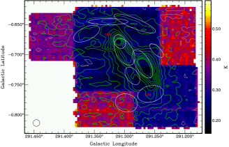 (c)
(c)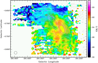 (d)
(d)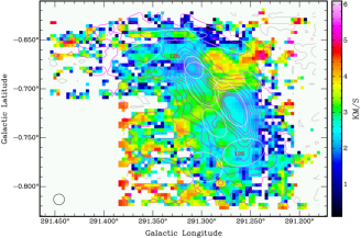
(a)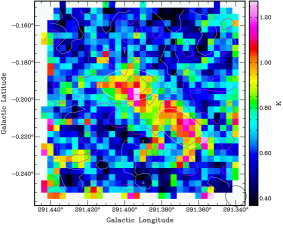 (b)
(b)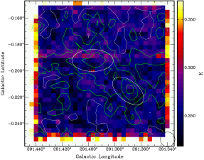
(c)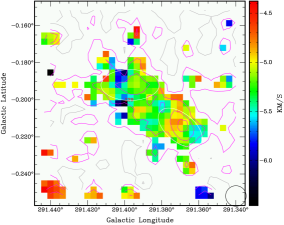 (d)
(d)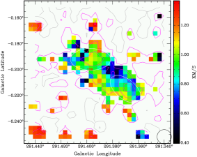
(a)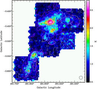 (b)
(b)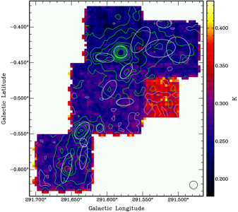 (c)
(c)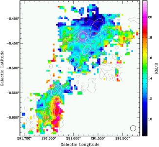 (d)
(d)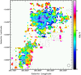
(a)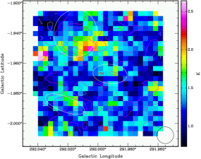 (b)
(b)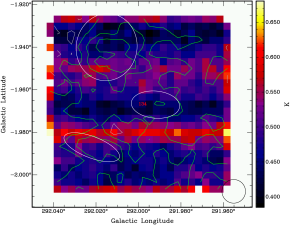
(c)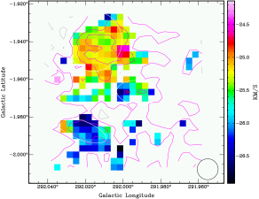 (d)
(d)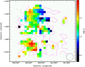
(a)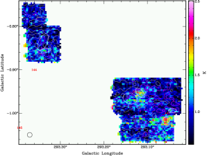 (b)
(b)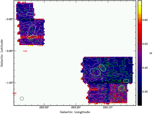 (c)
(c)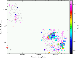 (d)
(d)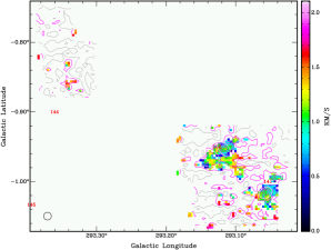
(a)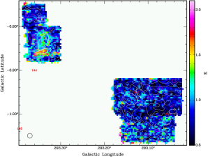 (b)
(b)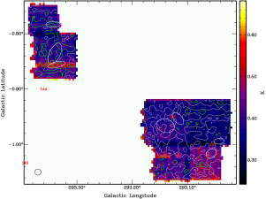 (c)
(c)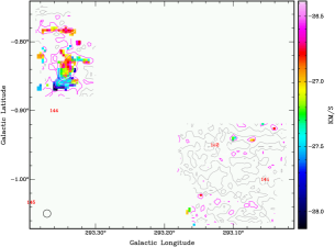 (d)
(d)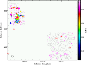
(a)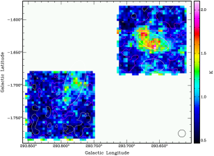 (b)
(b)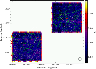 (c)
(c)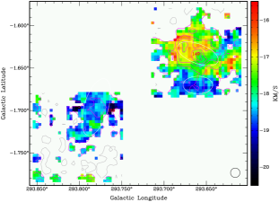 (d)
(d)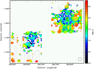
(a)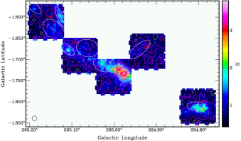
(b)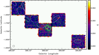
(c)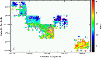
(d)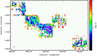
(a)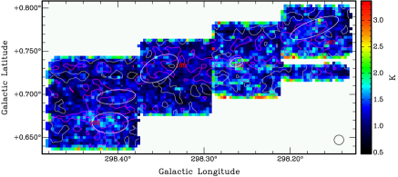
(b)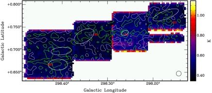
(c)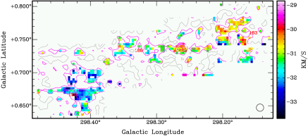
(d)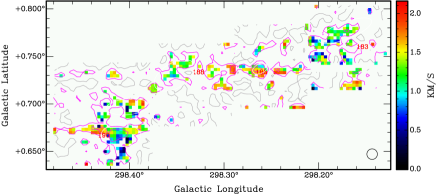
(a)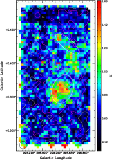 (b)
(b)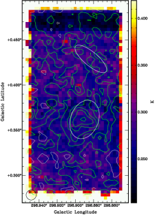
(c)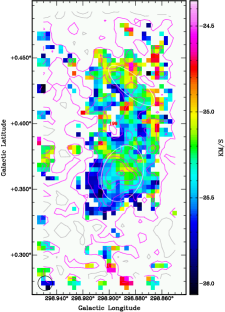 (d)
(d)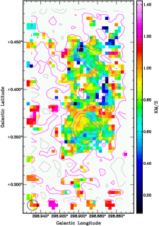
(a)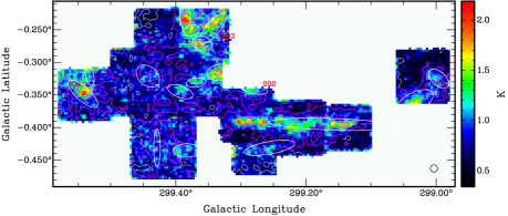
(b)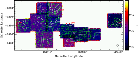
(c)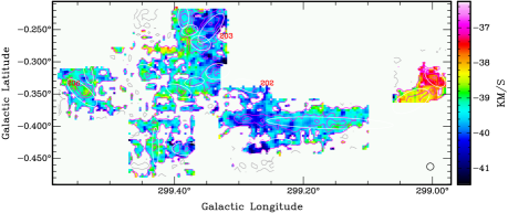
(d)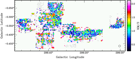
References
- Alves et al. (2007) Alves JF, Lombardi M, & Lada CJ 2007, A&A, 462, L17
- André et al. (2000) André, P., Ward-Thompson, D., & Barsony, M. 2000, in Protostars and Planets IV, eds. Mannings, V., Boss, A. P., Russell, S. S. (Tucson: U. of Arizona Press), p59
- Bally & Zinnecker (2005) Bally, J., & Zinnecker, H. 2005, AJ, 129, 2281
- Banerjee & Pudritz (2007) Banerjee R & Pudritz R E 2007, ApJ, 660, 479
- Barnes et al. (2001) Barnes, D.G. and 38 co-authors 2001, MNRAS, 322, 486
- Barnes & Crutcher (1990) Barnes, P.J., & Crutcher, R. 1990, ApJ, 351, 176
- Barnes et al. (2006) Barnes P.J., Yonekura Y, Miller A, Mühlegger M, Agars L, Wong T, Ladd E F, Mizuno N, & Fukui Y 2006, in IAU Symposium 231: Astrochemistry Throughout the Universe, D. Lis, G.A. Blake, E. Herbst (eds.) (Cambridge UP: Cambridge)
- Barnes et al. (2010) Barnes P J, Yonekura Y, Ryder S D, Hopkins A M, Miyamoto Y, Furukawa N, & Fukui Y 2010, MNRAS, 402, 73
- Beccari et al. (2010) Beccari G, and 24 co-authors 2010, ApJ, 720,1108
- Beltrán et al. (2006) Beltrán M T, Brand J, Cesaroni R, Fontani F, Pezzuto S, Testi L, & Molinari S 2006, A&A, 447, 221
- Benson & Myers (1989) Benson, P. J., Myers, P. C. 1989, ApJS, 71, 89
- Bertoldi & McKee (1992) Bertoldi F & McKee CF 1992, ApJ, 395, 140
- Beuther et al. (2002) Beuther, H., Schilke, P., Menten, K. M., Motte, F., Sridharan, T. K., & Wyrowski, F. 2002, ApJ, 566, 945
- Beuther et al. (2007) Beuther H, Churchwell EB, McKee CF, & Tan JC 2007, in Protostars and Planets V, B. Reipurth, D. Jewitt, and K. Keil (eds.) (Tucson: U. of Arizona Press), p165
- Bonnell et al. (2003) Bonnell I A, Bate M R, & Vine S G 2003, MNRAS, 343, 413
- Boulares & Cox (1990) Boulares A & Cox DP 1990, ApJ, 365, 544
- Bronfman et al. (1996) Bronfman L, Nyman L-Å, & May J 1996, A&AS, 115, 81
- Burton & Gordon (1978) Burton W.B. & Gordon M.A. 1978, A&A, 63, 7
- Caratti o Garatti et al. (2006) Caratti o Garatti A., Giannini T., Nisini B., & Lorenzetti D. 2006, A&A, 449, 1077–1088
- Caselli & Myers (1995) Caselli P & Myers P C 1995, ApJ, 446, 665
- Caselli et al. (2002) Caselli P, Walmsley C M, Zucconi A, Tafalla M, Dore L, & Myers P C 2002, ApJ, 565, 344
- Chen et al. (2010) Chen X, Shen Z-Q, Li J-J, Xu Y, & He J-H 2010, ApJ, 710, 150
- Churchwell (2002) Churchwell, E. 2002, ARAA, 40, 27
- Clemens (1985) Clemens, D.P. 1985, ApJ, 295, 422
- Crutcher (1999) Crutcher, R. M. 1999, ApJ, 520, 706
- Da Rio et al. (2010) Da Rio, N., Robberto, M., Soderblom, D.R., Panagia, N., Hillenbrand, L.A., Palla, F., & Stassun, K.G. 2010, ApJS, accepted, arXiv:1008.1265
- de Wit et al. (2005) de Wit, W. J., Testi, L., Palla, F., & Zinnecker, H. 2005, A&A, 437, 247
- Dutra et al. (2003) Dutra C M, Bica E, Soares J, & Barbuy B 2003, A&A, 400, 533
- Elmegreen (2000) Elmegreen, B. G. 2000, ApJ, 530, 277
- Elmegreen (2007) Elmegreen, B. G. 2007, ApJ, 668, 1064
- Evans (1999) Evans, N. J. II 1999, ARAA, 37, 311
- Falgarone et al. (2008) Falgarone E, Troland T H, Crutcher R M, & Paubert G 2008, A&A, 487, 247
- Faundez et al. (2004) Faundez S, Bronfman L, Garay G, Chini R, Nyman L-Å, & May J 2004, A&A, 426, 97
- Fontani et al. (2005) Fontani F, Beltrán MT, Brand J, Cesaroni R, Testi L, Molinari S, & Walmsley CM 2005, A&A, 432, 921
- Fuller et al. (2005) Fuller G A, Williams S J, & Sridharan T K 2005, A&A, 442, 949
- Gao & Solomon (2004a) Gao, Y., & Solomon, P. M. 2004a, ApJ, 606, 271
- Gao & Solomon (2004b) Gao, Y., & Solomon, P. M. 2004b, ApJS, 152, 63
- Garrod et al. (2008) Garrod R T, Widicus-Weaver S L, & Herbst E 2008, ApJ, 682, 283
- Goodman et al. (1998) Goodman AA, Barranco JA, Wilner DJ, & Heyer M 1998, ApJ, 504, 223
- Grabelsky et al. (1988) Grabelsky D A, Cohen R S, Bronfman L, & Thaddeus P 1988, ApJ, 331, 181
- Gutermuth et al. (2009) Gutermuth RA, Megeath ST, Myers PC, Allen LE, Pipher JL, & Fazio GG 2009, ApJS, 184, 18
- Haynes et al. (1978) Haynes R F, Caswell J L, & Simons L W J 1978, Aust J Phys Astrophys Suppl, 45, 1
- Higuchi et al. (2009) Higuchi AE, Kurono Y, Saito M, & Kawabe R 2009, ApJ, 705, 468
- Hoversten & Glazebrook (2008) Hoversten, E. A., & Glazebrook, K. 2008, ApJ, 675, 163
- Johnstone & Bally (2006) Johnstone, D. & Bally, J. 2006, ApJ, 653, 383
- Kennicutt (1998) Kennicutt, R. C., 1998, ApJ, 498, 541
- Keto & Klassen (2008) Keto, E. & Klassen, P. 2008, ApJ, 678, L109
- Klaassen & Wilson (2007) Klaassen PD & Wilson CD 2007, ApJ, 663, 1092
- Koda et al. (2009) Koda, J. and 22 co-authors 2009, ApJL, 700, L132
- Krumholz & Tan (2007) Krumholz, M. R. & Tan, J. C. 2007, ApJ, 654, 304
- Krumholz & Thompson (2007) Krumholz, M. R. & Thompson, T. A. 2007, ApJ, 669, 289
- Lada & Lada (2003) Lada, C. J., & Lada, E. A. 2003, ARA&A, 41, 57
- Lada et al. (2008) Lada CJ, Muench AA, Rathborne J, Alves JF, & Lombardi M 2008, ApJ, 672, 410
- Ladd et al. (2005) Ladd E. F., Purcell C. R., Wong T., & Robertson S., 2005, PASA, 22, 62
- Larson (1981) Larson RB 1981, MNRAS, 194, 809
- Lee et al. (2003) Lee J-E, Evans N J, Shirley Y L, & Tatematsu K 2003, ApJ, 583, 789
- Leroy et al. (2008) Leroy, A. K., Walter, F., Brinks, E., et al. 2008, AJ, 136, 2782
- Longmore et al. (2007) Longmore S N, Burton M G, Barnes P J, Wong T, Purcell C R, & Ott J 2007, MNRAS, 535, 572
- Loren et al. (1990) Loren R B, Wootten A, Wilking B A 1990, ApJ, 365, 269
- Mac Low & Klessen (2004) Mac Low, M.-M., & Klessen, R. S. 2004, Rev. Mod. Phys., 76, 125
- McKee & Tan (2003) McKee C F & Tan J C 2003 ApJ, 585, 850
- McQuinn et al. (2002) McQuinn, K. B. W., Simon, R., Law, C. J., Jackson, J. M., Bania, T. M., Clemens, D. P., & Heyer, M. H. 2002, ApJ, 576, 274
- Merrifield (1992) Merrifield, M. 1992, AJ, 103, 1552
- Mihalas & Binney (1981) Mihalas D. & Binney J. 1981, Galactic Astronomy, (WH Freeman: San Francisco)
- Moorey et al. (1997) Moorey G G, Sinclair M W, & Payne J M 1997, in IAU Symposium 170 — CO: Twenty-Five Years of Millimeter-Wave Spectroscopy, W B Latter et al. (eds.) (Kluwer), 441
- Myers et al. (1998) Myers P C, Adams F C, Chen H, & Schaff E 1998, ApJ, 492, 703
- Nakamura & Li (2005) Nakamura F & Li Z-Y 2005 ApJ, 631, 411
- Narayanan et al. (2008) Narayanan D, Cox T J, Shirley Y, Davé R, Hernquist L, & Walker C K 2008, ApJ, 684, 996
- Padoan & Nordlund (2002) Padoan, P., & Nordlund, A. 2002, ApJ, 576, 870
- Plume et al. (1997) Plume, R., Jaffe, D.T., Evans, N.J., II, Martin-Pintado, J., & Gomez-Gonzalez, J. 1997, ApJ, 476, 730
- Pirogov et al. (2007) Pirogov, L., Zinchenko, I., Caselli, P., & Johansson, L. E. B. 2007, A&A, 461, 523
- Rathborne et al. (2006) Rathborne, J. M., Jackson, J. M., Simon, R. 2006, ApJ, 641, 389
- Reid et al. (2009) Reid M.J., and 13 co-authors 2009, ApJ, 700, 137
- Rohlfs & Wilson (2006) Rohlfs K. & Wilson T.L. 2006, Tools of Radio Astronomy, 4th ed. (Springer: Berlin)
- Shu (1977) Shu F 1977 ApJ, 214, 488
- Sollins & Megeath (2004) Sollins, P. K., Megeath, S. T. 2004, AJ, 128, 2374
- Sridharan et al. (2002) Sridharan T K, Beuther H, Schilke P, Menten K M, & Wyrowski F 2002, ApJ, 566, 931
- Stolte et al. (2006) Stolte A, Brandner W, Brandl B, & Zinnecker H 2006, AJ, 132, 253
- Tan et al. (2006) Tan J C, Krumholz M R, McKee C F 2006, ApJ, 641, L121
- Tan (2010) Tan J C 2010, ApJL, 710, L88
- Williams et al. (2000) Williams J P, Blitz L, & McKee C F 2000, in Protostars and Planets IV, eds. Mannings, V., Boss, A. P., Russell, S. S. (Tucson: U. of Arizona Press), p97
- Wilson et al. (2006) Wilson W, Muller E, & Ferris D 2006, ATNF Newsletter, 59, www.atnf.csiro.au/news/newsletter/jun06
- Wu et al. (2010) Wu J, Evans N J II, Shirley Y L, & Knez C 2010, ApJS, 188, 313
- Yonekura et al. (2005) Yonekura Y, Asayama S, Kimura K, Ogawa H, Kanai Y, Yamaguchi N, Barnes P J, & Fukui Y 2005, ApJ, 634, 476
- Yonekura et al. (2011) Yonekura Y, Barnes P J, & Fukui Y 2011, The Galactic Census of High- and Medium-mass Protostars II. Properties of a Uniform Sample of Massive Molecular Clumps from Nanten Molecular Line Maps, in prep.
- Zinchenko et al. (2009) Zinchenko S., Caselli P., & Pirogov L. 2009, MNRAS, 395, 2234