24 rue Lhomond, F-75231 Paris Cedex 05, France 22institutetext: Centre for Quantum Technologies, National University of Singapore, Singapore 117543, Singapore 33institutetext: Institut Non Linéaire de Nice, Université de Nice Sophia-Antipolis, CNRS, Valbonne 06560, France
Large atom number dual-species magneto-optical trap for fermionic 6Li and 40K atoms
Abstract
We present the design, implementation and characterization of a dual-species magneto-optical trap (MOT) for fermionic 6Li and 40K atoms with large atom numbers. The MOT simultaneously contains 6Li-atoms and 40K-atoms, which are continuously loaded by a Zeeman slower for 6Li and a 2D-MOT for 40K. The atom sources induce capture rates of 6Li-atoms/s and 40K-atoms/s. Trap losses due to light-induced interspecies collisions of 65% were observed and could be minimized to 10% by using low magnetic field gradients and low light powers in the repumping light of both atomic species. The described system represents the starting point for the production of a large-atom number quantum degenerate Fermi-Fermi mixture.
1 Introduction
The study of ultracold atomic Fermi gases is an emerging research field aiming to understand many-body quantum phenomena occurring in various fields, such as condensed matter systems, disordered systems, quark-gluon plasmas or astrophysics (neutron stars) IngKet06 ; GioPit08 . They provide a unique opportunity to create strongly correlated many-body systems with a high degree of experimental control. One intends to realize analog quantum simulators in Feynman’s spirit Fey82 , with which many-body Hamiltonians could be solved.
In the field of ultracold Fermi gases the study of mixtures of two different fermionic species with different mass is gaining interest. Both theoretical and experimental aspects motivate this study. Such mixtures are predicted to exhibit a rich phase diagram such as phase separation HoCaz09 , crystalline phases PetAst07 , exotic pairing mechanisms ForGub05 and long-lived trimers LevTie09 . They further allow the creation of polar molecules, which have a long-range dipole-dipole interaction DeiGro08 ; NiOsp08 . Two different atomic species yield additional tunable parameters, such as the mass imbalance and species-specific potentials. The mass-imbalance can be varied in an optical lattice, where the effective mass of each species depends on the optical lattice parameters.
The mixture 6Li-40K is a prime candidate for these studies. 6Li and 40K are the only stable fermionic alkali isotopes and thus belong to the experimentally best-mastered class of atoms. Moreover, both species have bosonic isotopes which can also be used to create boson-fermion gases. Furthermore, the mass difference between the two species is large leading to a large electric dipole moment for heteronuclear diatomic molecules (3.6 D) AymDul05 . Finally, many of the above-mentioned predicted quantum phases require strong interspecies interactions and a universal behavior of the gas. It was recently reported TieGoo10 that it is possible to reach the universal regime for the 6Li-40K-mixture due to the existence of a 1.5 Gauss-wide Feshbach resonance.
The starting point of most mixture experiments is a dual-species magneto-optical trap. It is desirable to capture a large number of atoms at this stage for the following reasons. First, large atom numbers allow to anticipate the losses induced by the subsequent evaporative cooling procedure, which needs to be applied to reach the quantum degenerate regime. Second, a large initial atom number makes the evaporation procedure more efficient. Third, the Fermi temperatures of the gas are larger for larger atom numbers and thus quantum phenomena can be observed at higher temperatures. Finally, a large atom number leads to better signal-to-noise ratios and a greater robustness in day-to-day operation.
A dual-species magneto-optical trap with large atom numbers also allows an efficient creation of ultracold heteronuclear molecules via photoassociation. Using this technique, we have been able to create excited heteronuclear 6Li-40K* molecules with a formation rate of s-1. The results of this experiment will be the subject of a separate publication RidCha11b .
In this article we describe the design, implementation and characterization of a dual-species magneto-optical trap for 6Li and 40K with large atom numbers. In a dual-species MOT, the atom number is in general reduced compared to single-species MOTs due to additional interspecies collisions and to experimental constraints, such as the imperative to use the same magnetic field for both species or common optics. In other groups working with the 6Li-40K mixture the following atom numbers have been achieved: in the Munich group TagVoi06 the dual-species MOT is loaded from a Zeeman slower for 6Li and a vapor for 40K, resulting in atom numbers of (6Li) and (40K). In the Innsbruck group SpiTre10 the dual-species MOT is loaded from a multi-species Zeeman slower and atom numbers of (6Li) and (40K) are achieved. In the group in Amsterdam Tie09 two separate 2D-MOTs allow to load (6Li) and (40K). In our setup, the dual-species MOT is loaded from a Zeeman slower for 6Li and a 2D-MOT for 40K. It simultaneously contains 6Li-atoms and 40K-atoms, which represents a substantial atom number improvement.
For our application in particular a large atom number in the 40K-MOT is of interest, since we intend to sympathetically cool 6Li with 40K, where 40K will be prepared and cooled in two different spin states. This approach has been implemented by Tiecke and coworkers TieGoo10 and proved to be an efficient cooling method, as it can be realized in a magnetic trap. In this cooling process mostly 40K-atoms will be lost.
In future experiments, the atoms stored inside the dual-species MOT will be polarized and magnetically transported to an ultra-high vacuum (UHV) environment with large optical access. There the atom cloud will be evaporatively cooled to quantum degeneracy in an optically plugged magnetic quadrupole trap. Finally it will be transferred into an optical trap to investigate many-body phenomena in lower dimensions.
This article is organized as follows. In Sec. 2 the experimental setup, including the vacuum assembly and the laser systems, is described. In Sec. 3 we present the design and the performance of the atom sources, which are used to load the dual-species MOT, i.e. a Zeeman slower for 6Li and a 2D-MOT for 40K. In Sec. 4, the dual-species MOT is characterized and a study of light-induced interspecies collisions is presented.
2 Experimental setup
2.1 Vacuum system
A three-dimensional view of the vacuum system is shown in Fig. 1.
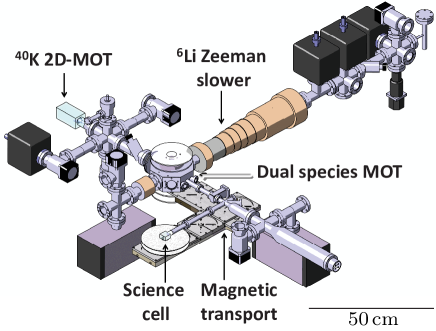
It consists of two atom trap chambers and three flux regions. The first chamber is a central octagonal chamber where the 6Li-40K dual-species MOT is prepared. The second chamber is a glass science cell, in which we will evaporatively cool the mixture to quantum degeneracy.
The three flux regions are all connected to the octagonal chamber and are divided in two parts. First, the atom sources, namely a 2D-MOT for 40K and a Zeeman slower for 6Li. Second, a magnetic transport connecting the octagonal chamber to the final science cell. This magnetic transport consists of a spatially fixed assembly of magnetic coils which creates a moving trapping potential of constant shape by applying time-varying currents GreBlo01 . It has already been implemented in our system and will be described in a separate publication.
The octagonal chamber can be isolated from the source regions and the science cell by all-metal UHV valves, which allow for separate baking and trouble-shooting. The 2D-MOT and the Zeeman slower region are pumped by one and three 20 l/s ion pumps, respectively. The octagonal chamber is pumped by a 40 l/s ion pump and the science chamber by a 40 l/s ion pump and a titanium sublimation pump. Differential pumping tubes connect the source regions to the octagonal chamber in order to create a high vacuum environment in the octagonal cell. In a similar way, the science chamber is connected to the octagonal chamber via a combination of standard CF16- and homemade vacuum tubes of 1 cm diameter to further increase the vacuum quality. The glass science cell has a large optical access and permits the installation of an objective for high-resolution imaging.
2.2 Laser systems
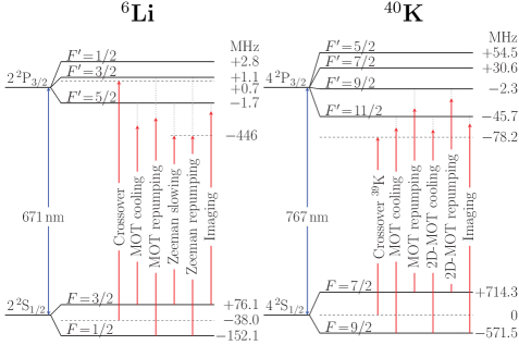
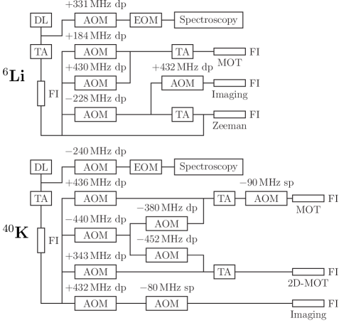
The dual-species MOT requires separate laser systems and optics for the two different atomic transition wavelengths 671 nm (Li) and 767 nm (K). The laser systems provide several beams with different frequencies and intensities for slowing, trapping and probing each atomic species. A sketch of the energy levels of the atomic species and the frequencies of interest are shown in Fig. 2. The laser systems are set up on separate optical tables and the generated laser beams are transferred to the main experimental table using optical fibers. A simplified scheme of the laser systems is shown in Fig. 3. Each one consists of a single low output-power frequency-stabilized diode laser (DL) and three tapered amplifiers (TAs) used for light amplification. Due to the small hyperfine splittings of both 6Li and 40K, the required frequencies of the various laser beams are conveniently shifted and independently controlled by acousto-optical modulators (AOMs).
The diode lasers are homemade tunable external cavity diode lasers in Littrow configuration. The laser diode for Li (Mitsubishi, ref. ML101J27) is of low-cost due to its mass production for the DVD industry. Its central free running output wavelength at room temperature is 660 nm which can be shifted into the range of 671 nm by heating the diode to 80∘C. In external cavity configuration its output power is 40 mW at a driving current of 150 mA. Under these conditions the laser diode reaches a typical lifetime of 6 months. It can be mode hop-free tuned over a range of 5 GHz. The laser diode for K is an anti-reflection coated Ridge-Waveguide Laser (Eagleyard, ref. EYP-RWE-0790-0400-0750-SOT03-0000), whose central free running output wavelength at room temperature corresponds to the desired wavelength. In external cavity configuration its output power is 35 mW at 90 mA and it has a typical lifetime of one year. It can be mode hop-free tuned over a range of 10 GHz.
The tapered amplifiers are commercial semiconductor chips which are mounted on homemade supports. We developed compact support designs with nearly no adjustable parts, which allow for a quick temperature stabilization, do not require running water for heat dissipation and allow for an easy installation process. The support designs are described in detail in the appendix.
We have also developed an all-solid-state laser for lithium delivering more than 630 mW output power, with which we intend to increase further the number of laser-cooled Li atoms. The setup of this light source is described elsewhere EisGer11 .
The frequency of each diode laser is stabilized via saturated absorption spectroscopy for which a small part of the DL’s output is used (see Fig. 3). A 20 MHz electro-optical modulator (EOM) is employed to modulate the phase of the spectroscopy laser beam yielding the derivative of the absorption signal through a lock-in detection. The resulting error signal is transferred to both the diode’s current (via a high frequency bias-tee), and, via a PID-controller, to a piezo that adjusts the external cavity’s length with a kHz bandwidth. An AOM is used to offset the frequency of the diode laser with respect to the absorption line used for locking. It allows for fine adjustments of the frequency while the laser is locked.
The Li diode laser frequency is shifted by MHz from the 6Li crossover signal and the K diode laser frequency is shifted by MHz from the conveniently located crossover signal of 39K. Note that the small excited state hyperfine structures of both 6Li and 39K are unresolved in the spectroscopy.
The saturated absorption spectroscopy for lithium is realized in a heat pipe of 50 cm length, in which a natural Li sample (with the isotopic abundances 7Li: , 6Li) is heated to 350∘C to create a sufficiently high vapor pressure for absorption. The heat pipe consists of a standard CF40 tube with the Li-sample placed at its center. The tube is heated with a pair of thermocoax cables which are wound around the tube in parallel with opposite current directions in order to prevent magnetic fields to build up. Condensation of lithium atoms on the cell windows needs to be inhibited as Li chemically reacts with glass. This is achieved by adding an argon buffer gas at mbar pressure, as Ar-Li collisions prevent Li to reach the cell windows in ballistic flight. The optimum argon pressure was chosen such that it provides enough collisions, but does not substantially collision-broaden the absorption spectrum. Water cooling of the metallic parts close to the windows leads to condensation of the diffusing lithium-atoms before those can reach the windows. To avoid that lithium slowly migrates to the colder surfaces, the inside of the tube is covered with a thin stainless steel mesh (Alfa Aesar, ref. 013477), which induces capillary forces acting on the condensed atoms. Since the surface tension of liquid lithium decreases with increasing temperature YakMoz00 , the capillary forces cause the atoms to move back to the hotter surfaces.
The saturated absorption spectroscopy for potassium is realized in a cylindrical glass vapor cell of 5 cm length, in which a natural K-sample (with the isotopic abundances 39K: , 40K: , 41K: ) is heated to 40∘C. Here, a small non-heated appendix of the cell serves as a cold point to prevent condensation of K-atoms on the surfaces crossed by the laser beam.
In both laser systems the frequency stabilized master laser beam is immediately amplified by a first TA and subsequently injected into a single-mode polarization maintaining optical fiber (FI) for beam shaping and spatial filtering (see Fig. 3). The output beam of the optical fiber is split by a series of polarizing beam splitters into several beams whose frequencies and intensities are independently shifted and controlled with AOMs in single or double pass configuration. The various beams are then recombined with a pair of polarizing beam splitters to linearly polarized bichromatic beams consisting of one cooling and one repumping frequency. Those are then either directly injected into a fiber or into another TA for further amplification. The fibers finally transfer the beams to the main experimental table.
The injection of a bichromatic beam into a TA, whose gain-medium is non-linear, is accompanied with the creation of sidebands FerMew99 . The sideband creation is due to parametric amplification of the gain medium by the beating between the two injected frequencies. In general, sidebands represent a loss of the power available in the injected frequencies and can excite unwanted transitions. In our case, where the two injected beam components have significantly different powers and frequencies (differing by MHz for 6Li and by MHz for 40K), the power losses are below 10%. No unwanted transitions are excited by the amplified bichromatic beams, except for the Zeeman slower beam, as that is detuned close to an integer multiple of 228 MHz and would thus perturb the atoms in the MOT. For this beam the injection of both frequency components into the same TA was thus avoided (see Fig. 3).
Acoustically isolated homemade mechanical shutters are placed in front of each fiber on the optical tables allowing to switch off the laser beams when required. The shutters consist of a low-cost solenoid-driven mechanical switch (Tyco Electronics, ref. T90N1D12-12) and a razor blade attached to it via a small rigid lever arm. These shutters typically have a closing time of s when placed in the focus of a laser beam and a sufficiently reproducible time delay of the order of 3 ms.
3 Atom sources
Magneto-optical traps can be loaded in different ways. The most efficient is the loading from a beam of slow atoms. This scheme allows isolating the MOT from the atom source region with a differential pumping tube, through which the beam is directed. The MOT thus can be located in a UHV chamber where collisions with the residual gas are minimized. Furthermore, the MOT will be quickly loaded when the atomic beam is cold and has a high flux. The most efficient methods to create such beams are Zeeman slowers and 2D-MOTs. For both atomic species 6Li and 40K, both, Zeeman slowers MewFer99 ; HadGup03 ; SpiTre10 and 2D-MOTs TieGen09 , have been realized in the past. In our setup we chose to implement a Zeeman slower for 6Li and a 2D-MOT for 40K.
3.1 6Li Zeeman slower
Introduction
Zeeman-tuned slowing represents one of the earliest and most widely used techniques to slow down atoms from an oven PhiMet82 . A Zeeman slower longitudinally decelerates an atomic beam using the radiative force of a counter-propagating resonant laser beam. The Doppler effect accumulated during the deceleration is compensated by the Zeeman effect, induced by an inhomogeneous magnetic field, which maintains the atoms on resonance and provides a continuous deceleration.
Two types of Zeeman slowers are commonly used: the positive-field and the sign-changing field (“spin-flip”) Zeeman slower MetStr99 . We have implemented a spin-flip Zeeman slower since it brings about several advantages. First, a smaller maximum absolute value of the magnetic field is required. Second, the Zeeman laser beam is non-resonant with the atoms exiting the slower and thus does not push them back into the slower, neither it perturbs the atoms trapped in the 6Li-MOT. However, the spin-flip Zeeman slower requires repumping light in the region where the magnetic field changes sign and thus makes the optics system slightly more complicated.
Experimental setup
The Zeeman slower consists of two distinct parts: the oven, which creates an atomic beam of thermal atoms, and an assembly of magnetic field coils. In the oven a nearly pure 6Li sample (5 g) is heated to 500C and an atomic beam is extracted through a collimation tube. The magnetic field coils create an inhomogeneous magnetic field along the flight direction of the atoms.
The oven consists of a vertical reservoir tube (diameter: 16 mm, length: 180 mm) and a horizontal collimation tube (diameter: 6 mm, length: 80 mm), which is attached to it (see Fig. 1). The upper end of the reservoir tube and the free end of the collimation tube are connected to CF40-flanges. The flange of the reservoir tube is sealed and allows connecting a vacuum pump for baking purposes. The flange of the collimation tube connects the oven to the rest of the vacuum chamber. All parts of the oven are made of stainless steel of type 302L and connected using nickel gaskets instead of copper gaskets as they stand higher temperatures and react less with lithium. The heating of the oven is realized with two high power heating elements (Thermocoax, ref. SEI 10/50-25/2xCM 10), wound around both, the reservoir and the collimation tube.
The temperature of the oven needs to be stabilized precisely, since the atomic flux critically depends on the temperature. This is accomplished by an active stabilization circuit and an isolation with glass wool and aluminum foil. Along the collimation tube a temperature gradient is maintained in order to recycle lithium atoms sticking to the inner tube walls through capillary action, as explained above. In order to amplify the effect of capillary action, a thin stainless steel mesh with a wire diameter of 0.13 mm (Alfa Aesar, ref. 013477) is placed inside the tube. This wire decreases the effective diameter of the collimation tube to mm. For the operating temperature of 500C, the vapor pressure of lithium in the oven amounts to mbar.
A computer controlled mechanical shutter (Danaher Motion, ref. BRM-275-03) in front of the oven allows to block the atomic beam during experiments or when the 6Li-MOT is not in operation.
The oven is pumped through the collimation tube with a 20 l/s ion pump and isolated from the main chamber via three differential pumping stages and the tube of the Zeeman slower. The pumping efficiency through the collimation tube is l/s resulting in a pressure drop of a factor . The second and third differential pumping tubes both have a length of 100 mm and a diameter of 5 mm and 10 mm, respectively. A 20 l/s ion pump is placed after each tube. In total a pressure drop of a factor of between the oven and the main chamber is obtained.
The assembly of the oven is a three-step procedure. First, the metallic parts of the oven are pre-baked at 600C during 48 h. Then, the oven is filled with the lithium sample under air atmosphere and baked again at 600C during 12 h in order to eliminate the impurities in the lithium sample (mostly LiH). Typically 50% of the sample is lost during this procedure. Then, the oven is connected to the rest of the vacuum chamber under an argon atmosphere, since argon does not react with lithium. Since argon damages ion pumps, the vacuum chamber is first pumped by a turbo molecular pump during 12 h before the ion pumps are finally launched and the oven is operational.
The Zeeman slower coils are mounted on a 65 cm long standard CF40 tube placed between the oven and the MOT chamber. A sketch of the coil assembly and the generated axial magnetic field profile are shown in Fig. 4. The coil assembly extends over cm and is separated from the position of the MOT by 16 cm. The coils are connected in series and were designed such that the desired magnetic field profile is generated for a moderate driving current of 12 A. The axial magnetic field of the slower along the flight direction of the atoms is measured to be G at the entrance and G at the exit.
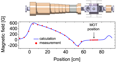
The magnetic field of the Zeeman slower is non-zero at the position of the MOT and hence compensated by a coil placed opposite to the slower coils at a distance of 12.7 cm from the MOT (see Fig. 4). The compensation coil consists of 4 coil layers wound around a 10 cm long CF40 standard tube. They are powered by a separate power supply for fine adjustments. When compensated, the magnetic field has an axial gradient of 0.5 G/cm at the position of the MOT.
The cables of the Zeeman slower coils (APX France, ref. méplat cuivre émaillé CL H ) stand bake out procedures up to 200C. One layer of a heating cable (Garnisch, ref. GGCb250-K5-19) is permanently placed underneath the magnetic field coils for these bake out procedures. To avoid heating of the vacuum parts during the Zeeman slower’s operation, two layers of water coils were wound underneath the coil layers.
Slowing and repumping light for the Zeeman slower is derived from a bichromatic laser beam which is provided by an optical fiber originating from the laser system. It has a total power of mW and its frequencies are both red detuned by from the slowing and the repumping transition (see Fig. 2). The intensity of the slowing light is 8 times bigger than the intensity of the repumping light. Both beam components have the same circular polarization ( at the position where the atoms enter the slower).
The detuning of the slowing light and the axial magnetic field at the entrance of the coil assembly define the so-called capture velocity of the Zeeman slower. All atoms with a velocity smaller than are expected to be decelerated to the same final velocity at the exit of the slower, provided that they initially populate the correct internal atomic state. The resonance condition for the atoms inside the slower yields m/s and m/s. The exit velocity of the slower is thus larger than the capture velocity of the 6Li-MOT, which is estimated to be m/s. However, the atoms are still decelerated significantly in the region between the slower exit and the MOT and are thus expected to be captured by the MOT. The capture velocity of the Zeeman slower is smaller than the most probable thermal speed of the atomic beam, which is given by m/s at C, where denotes the Boltzmann constant and the mass of the 6Li-atoms.
The bichromatic Zeeman slower beam is expanded and focused by a lens pair. The focusing of the beam accounts for the divergence of the atomic beam and the loss of beam power due to absorption and thus yields an efficient utilization of the available laser power. In addition, it induces a small cooling effect along the transverse direction MetStr99 . The 1/e2-diameter at the position of the MOT is 31 mm and the focus is at a distance of 120 cm from the MOT, 10 cm behind the oven.
The divergence of the atomic beam is an important parameter characterizing the Zeeman slower. Three factors contribute to it: first, the geometry of the oven’s collimation and the subsequent differential pumping tubes, second the atom’s deceleration inside the slower, and third the transverse heating due to the scattered photons during the slowing process. In order to estimate the divergence of the atomic beam, we calculate the maximum possible deflection of an atom which exits the oven with a longitudinal velocity . An atom with this velocity needs ms to reach the exit of the Zeeman slower and additional ms to reach the MOT. Due to the geometry of the collimation and differential pumping tubes it can have a maximum transverse velocity of 16 m/s. The change in transverse velocity due to the heating is calculated to be m/s JofKet93 and is thus negligible with respect to the maximum transverse velocity determined by the tube geometry. The final transverse displacement of the atom with respect to the beam axis at the position of the 6Li-MOT would thus be cm, resulting in an effective beam divergence of 90 mrad. This divergence requires 6Li-MOT beams of a large diameter.
Experimental results
For our application the essential parameter which characterizes the performance of the Zeeman slower is the capture rate of the 6Li-MOT. We studied its dependence as a function of several Zeeman slower parameters, such as: the temperature of the oven, the power of the slowing light, the magnitude of the magnetic field and the intensity ratios between the repumping and slowing light. The optimized values of these parameters are displayed in Tab. 1, leading to a 6Li-MOT capture rate of atoms/s. The capture rate was deduced from a very short loading of the MOT, for which atom losses can still be neglected (250 ms).
| 6Li Zeeman slower | |
|---|---|
| 50 | |
| -75 | |
| -75 | |
| 1/8 | |
| 570 |
Figure 5 (a) shows the dependence of the 6Li-MOT capture rate on the power of the Zeeman slowing light. The curve increases with increasing beam power and indicates saturation for higher powers. In the experiment the slowing light power is 45 mW, for which the curve in Fig. 5 (a) starts to saturate, demonstrating that the size of the slowing beam is well chosen. In particular it shows that the beam is not absorbed significantly by the atoms inside the slower.
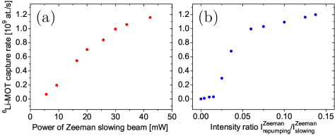
The dependence of the 6Li-MOT capture rate on the intensity ratio between repumping and slowing light of the Zeeman slower is depicted in Fig. 5 (b). The curve increases with increasing repumping intensity and saturates for higher intensities. For the intensity ratio the repumping intensity in the region where the magnetic field of the Zeeman slower changes sign, is of the order of the saturation intensity. Therefore the transition probability of the repumping transition saturates at , explaining the behavior in Fig. 5 (b). The graph shows that the Zeeman slower only requires a small repumping intensity. It is important that the repumping light has the same circular polarization as the slowing light, since it helps to optically pump the atoms to the cycling transition used for slowing.
Figure 6 (a) shows the 6Li-MOT capture rate as a function of the magnitude of the axial magnetic field of the Zeeman slower. The position of the maximum depends on the detuning of the slowing light.
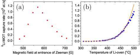
Figure 6 (b) shows the dependence of the 6Li-MOT capture rate on the oven temperature (circles) as well as a (scaled) theoretical prediction (solid curve) for the experimental data. The curve shows a nearly exponential increase of the capture rate with the temperature. The theoretical prediction is based on a model which assumes no collisions between the atoms (i.e., no intrabeam collisions and no collisions between the beam and the MOT atoms). It is derived as follows.
In the absence of collisions, the normalized velocity distribution of the Zeeman-slowed atoms exiting the slower does not depend on the temperature of the oven. Assuming that the 6Li-MOT captures mainly atoms which have been slowed by the Zeeman slower, the capture rate of the 6Li-MOT is a temperature-independent fraction of the flux of the Zeeman-slowed atoms: . The proportionality constant depends on the divergence of the atomic beam and the capture velocity of the 6Li-MOT. The flux of the Zeeman-slowed atoms is given by the flux of the oven atoms which have a speed smaller than the Zeeman slower’s capture velocity and which are in the correct internal atomic state to be decelerated by the Zeeman slower (i.e. , ). Assuming the oven to be in thermal equilibrium, is given by Ram86 ; TieGen09
| (1) |
with a temperature-independent constant , which equals the fraction of atoms which are in the correct internal atomic state. is the atomic density in the oven, m2 the aperture surface of the oven, the solid angle of the atomic beam (with the aperture surface of the last differential pumping tube and the distance between the two aperture surfaces ) and , with the emission angle with respect to the oven axis. is the normalized speed distribution function given by
| (2) |
Since the solid angle of the atomic beam is small, it is and thus .
The explicit temperature dependence of the 6Li-MOT capture rate is then obtained via by substituting into Eq. (1) the ideal gas equation and the relation for the saturated vapor pressure , with mbar and the latent heat of vaporization K AlcItk84 . This relation applies to the temperature range 300-500C with an accuracy of 5%. Thus, we have
| (3) |
with . Scaling Eq. 3 to the experimental data for a given (low) temperature (C) yields the theoretical prediction for the curve shown in Fig. 6. The scaling yields , thus of the atoms, which enter the Zeeman slower with a velocity smaller than , are captured by the 6Li-MOT.
The main contribution to the small value of is the large divergence of the slowed atomic beam: is proportional to the ratio of the atomic beam cross section and the capture surface of the 6Li-MOT, which is estimated to (assuming the 6Li-MOT capture surface to be a circle of cm diameter). Two-dimensional transverse laser cooling of the atomic beam could vastly increase the value of . The remaining are due to an inefficient capture of the 6Li-MOT and to a significant fraction of oven atoms occupying the incorrect internal atomic states.
The obtained theoretical prediction agrees well with the experimental data for temperatures below 475C (see Fig. 6 (b)). For temperatures above 475C, the experimental data deviate from the prediction indicating that intrabeam collisions or collisions between the atoms in the beam and the MOT become important. We found that for T=500C collisions between the thermal 6Li beam and the trapped 6Li-MOT atoms indeed take place, which we verified by measuring the lifetime of the 6Li-MOT in presence and absence of the thermal 6Li beam, making use of the mechanical block placed at the exit of the oven. The lifetime was found larger for the case where the thermal 6Li beam was blocked. In a similar way the thermal 6Li beam also affects the lifetime of the 40K-MOT. In order to avoid a reduction of the number of trapped 40K atoms in the dual-species MOT, we therefore limit the 6Li-oven temperature to 500C.
With the help of Eq. 1 the lifetime of the oven can be estimated. Assuming that the collimation tube of the oven recycles all atoms sticking to its wall and the vacuum pumps have no impact on the Li pressure in the oven, the total atomic flux through the collimation tube is obtained by replacing , and cm (the length of the collimation tube) in Eq. 1. For the working temperature C the lithium vapor pressure is mbar, corresponding to a density m-3. Thus, the atom flux through the collimation tube is s kg/s. With 3 g of 6Li this corresponds to an oven lifetime of years. (The importance of the recycling becomes manifest when comparing this value to the hypothetical lifetime of the oven, would the collimation tube be replaced by an aperture of the same surface. In this case the atom flux through this aperture would be and thus days.)
3.2 40K 2D-MOT
Introduction
2D-MOTs have been widely used over the past years to produce high flux beams of cold atoms DieSpr98 ; SchBat02 ; CatMai06 ; ChaRoy06 ; TieGen09 ; SpiTre10 . In some cases they offer advantages over the more common Zeeman slowers. Even though Zeeman slowers can produce higher fluxes and are more robust, they have the following disadvantages. They produce unwanted magnetic fields close to the MOT which need to be compensated by additional fields, they require a substantial design and construction effort and are space consuming. The atomic beam source of Zeeman slowers needs to be operated at higher temperatures than the vapor cell used as source for 2D-MOTs and the material consumption can be high. In the case of the rare isotope 40K, this drawback is major: no pure source of 40K exists and enriched 40K samples are very expensive (4000 Euros for 100 mg of a 4% enriched sample). Therefore a 40K Zeeman slower would be very costly. A 2D-MOT can be operated at lower pressures and is thus more economic. In addition it allows separating 40K from the more abundant 39K, since it produces an atomic beam which nearly only contains the slowed atoms (i.e. no thermal background). These considerations motivated us to implement a 2D-MOT for 40K.
Principle of operation
In a 2D-MOT, an atomic vapor is cooled and confined transversally and out-coupled longitudinally through an aperture tube. The role of the aperture tube is two-fold. First, it isolates the 2D-MOT from the MOT chamber by differential pumping, and second, it acts as a geometric velocity filter, since only atoms with a small transverse velocity pass through. As the transverse cooling is more efficient for atoms which have a small longitudinal velocity—since those spend more time in the cooling region—most of the transversally cold atoms are also longitudinally cold. Thus, the filter indirectly filters atoms also according to their longitudinal velocity. A 2D-MOT thus produces an atomic beam which is transversally and longitudinally cold.
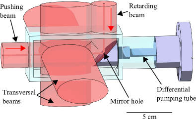
The flux of a 2D-MOT can be improved by adding a longitudinal molasses cooling to the 2D-MOT configuration DieSpr98 . Thus, the atoms spend more time in the transverse cooling region due to the additional longitudinal cooling. The longitudinal beam pair is referred to as the pushing and the retarding beam, where the pushing beam propagates in the direction of the atomic beam (see Fig. 7). We implemented such a configuration, making use of a -angled mirror inside the vacuum chamber. This mirror has a hole at its center which creates a cylindrical dark region in the reflected retarding beam. In this region, the atoms are accelerated along the longitudinal direction by the pushing beam only, which allows an efficient out-coupling of the atomic beam.
Experimental setup
The vacuum chamber of the 2D-MOT consists of standard CF40 components and a parallelepipedical glass cell (dimensions 110 mm55 mm55 mm), which is depicted in Fig. 7. Its long axis is aligned horizontally, parallel to the differential pumping tube and the direction of the produced atomic beam. The mirror inside the vacuum chamber is a polished stainless steel mirror with an elliptical surface (diameters 3.0 cm and 4.2 cm). It is attached to the differential pumping tube inside the vacuum. It allows to overlap the two longitudinal laser beams whose powers and orientations can thus be independently controlled externally. The mirror’s material has a reflectivity of only , but inhibits chemical reaction of potassium with its surface. The differential pumping tube intercepts the mirror at its center. The tube has a diameter of 2 mm over a distance of 1.5 cm and then stepwise widens up to 10 mm over a total distance of 22 cm. The 40K-MOT is located 55 cm away from the 2D-MOT center. Assuming a ballistic flight of the atoms, the geometry of the differential pumping tube defines an upper limit of the divergence of the atomic beam, which is calculated to be 35 mrad. The atomic beam thus is expected to have a diameter of cm when it reaches the 40K-MOT. The differential pumping tube has a conductance of 0.04 l/s. The generated pressure ratio between the 2D-MOT and the 3D-MOT chambers is .
The potassium source is an isotopically enriched 40K sample (containing 4 mg of 40K, 89.5 mg of 39K and 6.5 mg of 41K, from Technical Glass Inc., Aurora, USA), placed at a distance of 20 cm from the glass cell. It was purchased in a small ampule which was broken under vacuum inside a modified stainless steel CF16 bellow. The small vapor pressure of potassium at room temperature ( mbar) requires heating of the entire 2D-MOT chamber. We heat the source region to 100∘C, all intermediate parts to 80∘C and the glass cell to 45∘C. The gradient in temperature ensures that the potassium migrates into the cell and remains there. The resulting K-pressure in the glass cell was measured by absorption of a low intensity probe. We found mbar, which implies a partial pressure of the 40K-isotope of mbar. In contrast to lithium, the source lifetime is mainly determined by the pumping speed of the ion pump. At the measured pressure the lifetime of the source is estimated to years.
Four air-cooled rectangular shaped elongated racetrack coils (dimensions 160 mm60 mm) are placed around the glass cell to produce a 2D quadrupole field with cylindrical symmetry and a horizontal line of zero magnetic field. This racetrack coil geometry allows an independent control of the transverse position of the magnetic field zero, and minimizes finite coil fringe effects at the coil ends. The coils are controlled by four separate power supplies. For optimized operation, the transverse magnetic field gradients are G/cm.
Cooling and repumping light for the 2D-MOT is derived from a bichromatic laser beam which is provided by an optical fiber originating from the laser system. It has a total power of mW and its frequencies are red detuned by from the cooling and by from the repumping transition (see Fig. 2). The beam is separated into four beams and expanded by spherical and cylindrical telescopes to create the transverse and longitudinal 2D-MOT beams. The transverse beams have an elliptical cross section (1/e2-diameters: 27.5 mm and 55 mm), are circularly polarized and retro-reflected by right-angled prisms, which preserve the helicity of the beams. The power losses in the surface of the glass cell and the prisms weaken the power of the retro-reflected beams by % (the loss contribution of the absorption by the vapor is negligible due to the high laser power). This power imbalance is compensated by shifting the position of the magnetic field zero. The longitudinal beams are linearly polarized and have a circular cross section (1/e2-diameter: 27.5 mm). of the fiber output power is used for the transverse beams, for the longitudinal beams. The intensity ratio between pushing and retarding beam along the atomic beam axis is (for reasons explained below).
Experimental results
For our purpose the essential parameter which characterizes the performance of the 2D-MOT is the capture rate of the 40K-MOT. We studied its dependence as a function of several 2D-MOT parameters, such as: the vapor pressure in the 2D-MOT cell, the total cooling light power, the detuning of the cooling frequency and the intensity ratios between the repumping and cooling light and between the pushing and retarding beam. The optimized values of these parameters are displayed in Tab. 2, leading to a 40K-MOT capture rate of atoms/s.
| 40K 2D-MOT | |
|---|---|
| 450 | |
| -3.5 | |
| -2.5 | |
| 1/2 | |
| 6 | |
| 11 | |
| K vapor pressure [mbar] |
The mean velocity of the atoms in the atomic beam can be estimated as follows. It is approximately given by the average time required for the atoms of the 2D-MOT region to reach the 3D-MOT. This time was measured by recording the time delay of the onset of the 40K-MOT loading after switching on the 2D-MOT beams. We measured a time delay of 23 ms and deduce a mean longitudinal velocity of the captured atoms of 24 m/s. At this velocity, the displacement due to gravity of the beam of atoms from the 40K-MOT center is 2.6 mm, which is negligible compared to the size of the 40K-MOT beams and the divergence of the atomic beam.
Figure 8 (a) shows the dependence of the 40K-MOT capture rate on the detuning of the 2D-MOT cooling light. The curve has a maximum at and a full width at half maximum (FWHM) of . The maximum is the result of two opposing effects: the scattering force of the 2D-MOT beams decreases with increasing detuning whereas the capture velocity increases MetStr99 . The first effect implies a less efficient transverse cooling whereas the second leads to a more efficient capture of atoms. An additional effect might influence the shape of the curve: since the scattering force of the pushing beam depends on the detuning, also the mean-velocity of the atomic beam depends on it DieSpr98 ; SchBat02 ; ChaRoy06 . Since we measure the 40K-MOT capture rate rather than the flux of the 2D-MOT, the mean-velocity might exceed the capture velocity of the 40K-MOT. However, as shown in refs. DieSpr98 ; SchBat02 ; ChaRoy06 , the mean-velocity of the beam only slightly changes with the detuning, such that we expect this effect to only weakly influence the curve. From the shape of the curve we conclude that the 40K-MOT capture rate is not very sensitive to changes of .
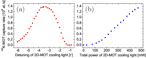
The dependence of the 40K-MOT capture rate on the total power of the 2D-MOT cooling light is depicted in Fig. 8 (b). The total power refers to the sum of the powers in the six 2D-MOT beams. According to the chosen beam sizes, the maximum power of 470 mW corresponds to a total intensity of (for zero detuning) at the center of the 2D-MOT, with the saturation intensity given in Tab. 3. The curve almost linearly increases with light power without a clear indication of saturation. The increase is due to two effects. First, the 2D-MOT capture velocity increases with laser power due to the power broadening of the atomic spectral lines. Second, the scattering force increases, resulting in a steeper transverse confinement, which facilitates the injection of the atoms into the differential pumping tube. At some point, the curve is expected to saturate, since the temperature of the cooled atoms and light-induced collisions between them increase with light power. These effects, however, are less limiting in a 2D-MOT as compared to a 3D-MOT, since the atomic density in a 2D-MOT is typically three orders of magnitude smaller due to the absence of a three-dimensional confinement. Thus, in a 2D-MOT a high light power would be required to reach the regime of saturation.
Figure 9 (a) shows the dependence of the 40K-MOT capture rate on the intensity ratio between the cooling and repumping light of the 2D-MOT for the two different repumping detunings and and for a constant total cooling light power of 300 mW. The graph shows that for both frequencies the 40K-MOT capture rate increases with increasing repumping intensity and that it saturates at high intensities. It also shows that the maximum capture rate is bigger for the smaller detuning. The intensity dependence of the curves results from the likewise intensity dependence of the transition probability for an atomic transition. The maximum capture rate is bigger for the smaller detuning, since this detuning contributes more efficiently to the cooling process. In our experiment, a fixed total laser power is available for both repumping and cooling light. It is distributed such that the resulting capture rate is maximized. It was found to be maximum for an intensity ratio of . For that ratio the detuning also yields the maximum capture rate.
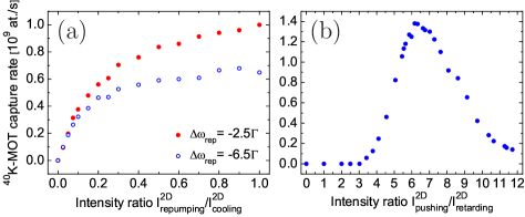
The dependence of the 40K-MOT capture rate on the intensity ratio between pushing and retarding beam is depicted in Fig. 9 (b). The curve has a maximum at . It is zero for values of between 0 and 3, then increases until the maximum and falls off again with a smaller slope. From the curve we can extract information about the importance of the reflectivity of the mirror inside the vacuum and of the size of its hole. For a given intensity ratio along the (horizontal) direction of the atomic beam, the mirror’s reflectivity determines the intensity ratio along the vertical direction above the reflecting surface of the mirror (see Fig. 7). If differs from 1, the atomic beam can experience a vertical deflection in this region. The hole inside the mirror creates a dark cylinder in the pushing beam after its reflection, so that in the region above the hole only light from the retarding beam has a vertical direction, which can also give rise to a vertical deflection of the atomic beam.
In the following we estimate the deflection of the atomic beam, which is induced by the unbalanced retarding beam in the small region above the hole. Assuming the atomic beam to have reached its final longitudinal velocity of 24 m/s when entering into the hole, the atoms spend 85 s in the region above the hole. Neglecting Doppler shifts and the presence of the pushing beam along the horizontal direction (no transverse beams are present in the region above the mirror), the atoms will scatter photons, with being the scattering rate MetStr99 for the given detuning and peak intensity . The recoil velocity of 40K being given by m/s, each atom will accumulate a transverse velocity of m/s. This leads to a downwards deflection of the atomic beam by an angle of mrad, which is more than a factor two bigger than the maximum deflection angle allowed by the differential pumping tubes. The atoms will thus not reach the 40K-MOT.
This deflection needs to be anticipated by an intensity imbalance in the region above the reflecting surface of the mirror, as that results in an upwards deflection of the atomic beam. For the given mirror reflectivity of , is equivalent to , which corresponds to the experimental observation depicted in Fig. 9 (b). The deflection of the atomic beam in the region above the hole could be avoided using a beam block which creates a dark cylinder in the region above the mirror which overlaps with the one in the pushing beam. In this configuration the position of the curve optimum in Fig. 9 (b) would change from to . For mirrors with a reflectivity close to 100% the position of the curve optimum could thus even be changed to , for which the longitudinal optical molasses cooling would be most efficient leading to a maximum 2D-MOT flux. Due to the polarization gradients generated by the transverse 2D-MOT beams the longitudinal optical molasses cooling is, however, still very efficient even in case of an intensity imbalance of 6 along the atomic beam axis.
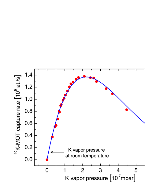
We now study the dependence of the 40K-MOT capture rate on the vapor pressure of potassium (all isotopes) in the 2D-MOT cell, which is shown in Fig. 10 (circles) together with a fit to a theoretical model (solid curve). The vapor pressure was measured by recording the absorption profile of a low intensity probe. The curve in Fig. 10 has a maximum at a vapor pressure of mbar. In the absence of collisions, the curve should increase linearly with pressure, which is indeed observed for low pressures. For high pressures, collisions become important and limit the 40K-MOT capture rate. The dependence of the 40K-MOT capture rate on the pressure can be described by the function ChaRoy06
| (4) |
where denotes the hypothetical capture rate of the 40K-MOT in the absence of collisions in the 2D-MOT chamber, denotes the collisional loss rate due to collisions in the 2D-MOT chamber between the cooled atoms and the background atoms, is the average time which the atoms spend inside the 2D-MOT cooling region, is the position-dependent atomic density in the atomic beam, and is the two-body loss rate coefficient which describes the cold collisions between the 40K atoms in the atomic beam. is proportional to the atomic density in the vapor cell, and , where is the effective collision cross section, and m/s the mean velocity of the thermal potassium atoms. The term describing the cold collisions is approximately proportional to due to the small density obtained in the 2D-MOT. For the investigated pressure range, the ratio only changes slightly with temperature and can thus be considered constant. Therefore Eq.(4) can be written as
| (5) |
with the constants , which are obtained from the fit shown in Fig. 10. At the curve’s maximum, the fit yields , showing that the collisions which limit the 40K-MOT capture rate are mainly the collisions with the hot background atoms, consisting mostly of 39K.
The background atoms are predominantly potassium atoms. These can collide either with the excited or the non-excited 40K-atoms of the atomic beam. Depending on the isotopes of the colliding partners, these collisions have different cross sections. Collisions between an excited and a non-excited atom of the same isotope usually have a very large cross section due to the strong resonant dipole-dipole interaction, described by a -potential. In 2D-MOT systems of other atomic species these collisions have been identified as the ones which limit the flux of the 2D-MOT DieSpr98 ; SchBat02 ; ChaRoy06 . In the case of 40K, the scattering rate for these collisions is reduced by the small abundance of 40K in the vapor. Therefore other collisions might limit the flux. In order to identify the flux-limiting collisions we calculate the cross section of different possible collisions and deduce the corresponding collision rates. The cross sections can be calculated using the approach described in ref. SteCho92 for losses out of a cold atom cloud. The cross section for collisions involving an excited and a non-excited 40K-atom is given by SteCho92
| (6) |
where is the mass of the 40K-atom, m/s is the estimated transverse velocity kick needed to make an atom miss the 40K-MOT, and Jm3 is the dispersion coefficient for the resonant dipole-dipole interaction DerJoh02 . The cross section for collisions involving a non-excited 40K-atom and a non-excited K-atom of the different isotopes is given by SteCho92
| (7) |
where Jm6 is the dispersion coefficient for the underlying van der Waals interaction DerJoh02 . Substituting the experimental parameters, one obtains: and . The resulting collision rates are proportional to the atomic densities and of the corresponding isotopes in the vapor and the relative number of excited 40K-atoms in the atomic beam, which was estimated to for the given beam detunings and intensities. One obtains
| (8) | |||||
| (9) | |||||
| (10) | |||||
| (11) |
( denoting the atomic density of potassium in the vapor cell). The dominant collision rate here is (Eq. (9)) for collisions involving a non-excited 40K-atom and a non-excited 39K-atom from the background. The largest collision rate for collisions between two 40K-atoms, , is by a factor of 10 smaller than . Therefore, collisions involving two 40K-atoms are not the collisions which limit the flux of the 2D-MOT. This is in contrast to 2D-MOT systems of other species. From the difference between and we conclude that the flux of the 2D-MOT for 40K could still be improved by about a factor of 10 by using a potassium sample of a higher isotopic enrichment.
4 6Li-40K dual-species MOT
Introduction
Previously, several groups have studied samples of two atomic species in a magneto-optical trap SanNus95 ; SchEng99 ; TelGar01 ; GolPap02 ; TagVoi06 ; SpiTre10 ; Tie09 . Here we report on the implementation and performance of our 6Li-40K dual-species MOT and on the study of collisions between atoms of the different species. After a description of the experimental setup, we start with a characterization of the single-species MOTs and then focus on the collisions in the dual-species MOT.
Principle of operation
In a magneto-optical trap six counter-propagating red-detuned overlapping laser beams cool and magneto-optically confine atoms in a magnetic quadrupole field around its zero MetStr99 . MOTs for alkali-atoms require laser light of two frequencies, namely the cooling and the repumping frequency. The latter ensures that the atoms stay in the cycling transition used for cooling. Typically the repumping light has a much lower power than the cooling light as the atoms principally occupy the states belonging to the cooling transition. For 6Li, however, the power of the repumping light needs to be relatively high, since 6Li has a very small hyperfine structure in the excited state manifold (of the order of the linewidth). When laser cooled, 6Li-atoms thus very likely quit the cooling transition. Therefore, the repumping light needs to contribute to the cooling process. As a consequence it needs to be present in all six directions with the same polarization as the cooling light. Therefore, we use bichromatic MOT-beams containing both cooling and repumping frequencies. We adapt the same strategy also for 40K.
Experimental setup
Light for the dual-species MOT is derived from two bichromatic laser beams, containing each a cooling and a repumping frequency, which are provided by two separate optical fibers originating from the respective laser systems. The beams are superimposed using a dichroic mirror and then expanded by a telescope to a 1/e2-diameter of 22 mm. All subsequent beam reflections are realized by two-inch sized broadband mirrors (Thorlabs, ref. BB2-E02-10). The beam is separated by three two-inch sized broadband polarization cubes (Lambda Optics, ref. BPB-50.8SF2-550) into four arms that form a partially retro-reflected MOT, in which only the vertical beam pair is composed of independent counter-propagating beams. Each retro-reflected MOT beam is focused with a lens of focal length 10 cm, placed at a distance of cm in front of the retro-reflecting mirror, in order to increase the intensity and therefore compensate for the losses in the optics and the light absorption by the trapped atoms. The distribution of the light power over the MOT beams is independently adjusted for the two wavelengths using a pair of custom-made wave plates, placed in front of each broad-band splitting cube. The wave plate pair consists of a plate of order 4 for the wavelength 767 nm and a plate of order 4 for the wavelength 671 nm. To a very good approximation each of these wave plates can turn the polarization direction for one wavelength without affecting the polarization for the other one (since it is and ). The circular polarization of the MOT beams is produced by first order plates for 767 nm, which work sufficiently well also for 671 nm. All four frequency components thus have the same circular polarizations in each beam. A mechanical shutter is placed in the focus of the telescope allowing to produce total extinction of the MOT light in addition to the partial and fast switching by the AOMs.
The bichromatic beam for the 40K-MOT has a total power of mW and its frequencies are red-detuned by from the cooling and by from the repumping transition (see Fig. 2). The intensity of the cooling light is times bigger than that of the repumping light. The bichromatic beam for the 6Li-MOT has a total power of mW and its frequencies are red-detuned by from the cooling and by from the repumping transition (Fig. 2). The power of the cooling light is times bigger than that of the repumping light.
The magnetic field for the dual-species MOT is created by a pair of coils in anti-Helmholtz configuration. The magnetic field gradient along the vertically directed symmetry axis is G/cm. This gradient yields an optimum atom number for the 40K-MOT.
The atoms in the dual-species MOT are probed by absorption imaging. In order to obtain a two-dimensional density profile of the atom cloud, three pictures are taken and recorded by a CCD-camera (PCO imaging, ref. Pixelfly qe). The first picture is taken with the imaging beam tuned near resonance and thus records the shadow cast by the atom cloud on the CCD-chip of the camera. The second picture is taken with the imaging beam tuned far off resonance (by ) and records the intensity profile of the imaging beam. The third picture is taken in absence of the imaging beam and records the background signal. The change of frequency of the imaging beam allows to take the first two pictures with a short time delay (2 ms), while keeping the imaging beam at the same frequency would require to wait for the atom cloud to disappear before the second picture could be recorded. Thus, the intensity fluctuations of the imaging beam during the recording process are minimized and both pictures can be taken with the same intensity.
Each atomic species requires its own imaging beam, which is provided by a separate optical fiber originating from the respective laser system (see Fig. 3). The two imaging beams are superimposed using a dichroic mirror and expanded by a telescope to a 1/e2-diameter of mm. The imaging beams have low intensity ( in the beam center), are circularly polarized and pass through the MOT along the horizontal direction, perpendicular to the axis of the quadrupole magnetic field of the MOT. No bias magnetic field is applied when absorption pictures are taken. The best atom number estimate from the measured absorption pictures is thus given by using an averaged squared Clebsch-Gordan coefficient, which is for 6Li and for 40K. Both beams are red detuned by from the and the cooling transitions of 40K and 6Li, respectively (see Fig. 2), so as to reduce saturation effects. For the chosen length of the imaging pulses (100 s) no repumping is required during the imaging process (we verified for 6Li that even in the case of a resonant imaging beam, the presence of a repumping beam would yield an increase of the detected atom number of only , which would be even less for 40K). In order to image the total number of atoms in the MOTs the atom clouds are exposed for 500 to only the repumping light before the image is taken in order to optically pump all atoms to the hyperfine ground state which is imaged. The overall uncertainty of the absolute atom number determination is estimated to be %.
Experimental results
In single-species operation we characterized the MOTs using the parameters for the optimized dual-species operation. We determined the atom numbers, the atomic densities in the cloud center, the loading times and the temperatures. Furthermore, we studied for each atomic species the dependence of the steady-state MOT atom number on the following parameters: the power and detuning of the cooling light and the intensity ratio between the repumping and cooling light. In dual-species operation, we studied the dependence of heteronuclear light-induced cold collisions on the laser power used for the MOT-beams. The optimum parameters, which lead to atom numbers of in the 40K-MOT and in the 6Li-MOT, are displayed in Tab. 3 together with the characteristics of the MOTs (in dual-species operation, the atom numbers only slightly change due to the additional interspecies collisions to in the 40K-MOT and in the 6Li-MOT). The -loading times of the MOTs are s for 40K and s for 6Li.
| 40K-MOT | 6Li-MOT | |
|---|---|---|
| 220 | 110 | |
| -3 | -5 | |
| -5 | -3 | |
| 6.04 | 5.87 | |
| per beam | 13 | 4 |
| 1.75 | 2.54 | |
| 1/20 | 1/5 | |
| 8 | 8 | |
| 8.9 | 5.4 | |
| 8.0 | 5.2 | |
| 3 | 2 | |
| 290 | 1400 |
Magneto-optical traps with large atom numbers have a high optical density and are optically dense for weak resonant laser beams. Therefore, when determining the atom number via absorption imaging, the frequency of the imaging beam has to be detuned, so not to “black out” the image.
Figures 11 (a,b) depict the detected atom number of the two MOTs (circles) as a function of the detuning of the imaging beam. The detected atom number was derived from the measured optical density assuming the imaging beam to be resonant. The curves are expected to have the shape of a Lorentzian with the peak centered around zero detuning. The experimental data shown in Figures 11 (a,b) clearly deviate from a Lorentzian behavior—they saturate for small magnitudes of the detuning. This deviation demonstrates that the MOTs are optically dense for small detunings. A correct estimate of the atom number is obtained from an extrapolation of the experimental data to zero detuning based on a Lorentzian fit of the curve wings (solid curves). A reliable extrapolation, however, requires imposing the width of the Lorentzian fit. In order to determine this width, an additional experiment was done (not shown): the data in Figs. 11 (a,b) were again recorded and fitted by a Lorentzian for a MOT with a small atom number and a low optical density (obtained by a short loading of 250 ms). The widths found by this additional measurement were for 40K and for 6Li. For 40K this width corresponds to the natural linewidth of the exited state addressed by the imaging transition. For 6Li the width is larger than the natural linewidth, since the small excited hyperfine structure is unresolved and thus its width () and the natural linewidth add up (this line broadening does not occur when a bias magnetic field is applied and a closed transition is used for imaging). The peak values of the Lorentzian fits in Figs. 11 (a,b) finally yield the atom numbers in the MOTs, given in Tab. (3).
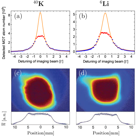
Figures 11 (c,d) show images of the MOTs and their doubly-integrated optical density profiles for the case of a resonant imaging beam. The flat top of as a function of position shows that the MOTs are optically dense. Their central optical densities for the resonant imaging beam are determined to be for 40K and for 6Li by the extrapolation technique described above. In addition, the density profiles in Figs. 11 (c,d) show that the MOTs have spatial extensions of the order of cm.
The atomic density in the MOT center is extracted from the recorded two-dimensional density profile as follows. The recorded profile is proportional to the atomic density integrated along the imaging beam direction : . When assuming that the MOT has cylindrical symmetry (with the symmetry axis along the -direction), the local atomic density at the MOT center is given by the maximum of the inverse Abel transform of , where is the -coordinate of the MOT center
| (12) |
with denoting the distance to the MOT center DriOss02 . Since the derivative is very sensitive to noise, the density profile is smoothened before its derivative is calculated. We obtain atoms/cm3 and atoms/cm3, respectively.
The temperature of the MOTs in single-species operation was determined by the time-of-flight method MetStr99 . The 40K-MOT has a temperature of 290 K and the 6Li-MOT of 1.4 mK. Both temperatures are higher than the Doppler cooling limit, because of the high intensity in the MOT beams. In addition, for 6Li, the unresolved excited hyperfine structure (see Fig. 2) inhibits sub-Doppler cooling effects. The same temperatures are found in dual-species operation. The measured temperatures and atomic densities yield the peak phase space densities and with the thermal de Broglie wavelength , respectively.
The dependence of the MOT atom number on the detuning of the cooling light is depicted in Figs. 12 (a,b). The atom number is maximum at for 40K and at for 6Li, and has a FWHM of and , respectively.
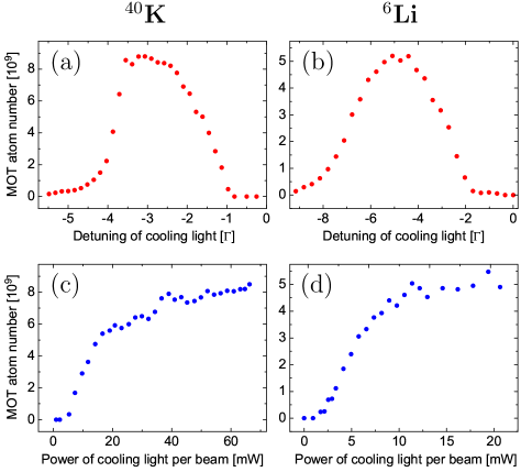
Figures 12 (c,d) show the dependence of the MOT atom number on the power of the cooling light per MOT beam. In the figures, a power of 10 mW corresponds to an on-resonance peak intensity of (Fig. 12 (c)) and (Fig. 12 (d)) in each of the six MOT beams. The atom number increases with increasing light power and saturates for higher powers. The saturation is due to several effects. First, the absorption probability for the cooling light saturates for high intensities. Second, the repulsive forces between the atoms due to rescattered photons and the temperature of the cloud increase with increasing light power SteCho92 . Finally the scattering rate for light-induced cold collisions increases with increasing light power.
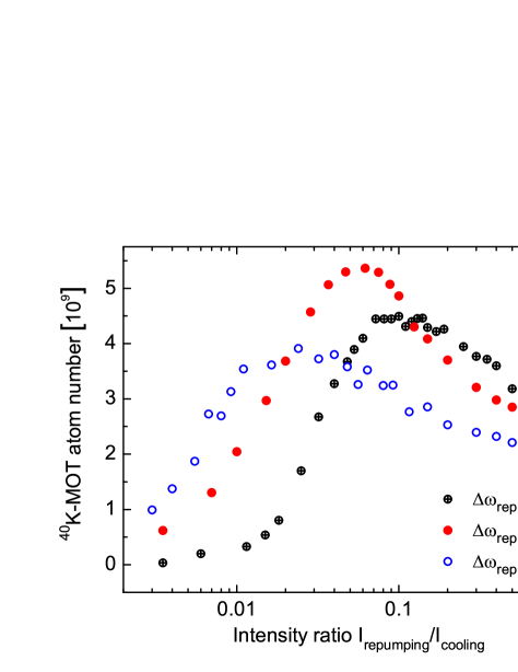
Figure 13 shows the dependence of the 40K-MOT atom number on the intensity ratio between repumping and cooling light for three different repumping detunings , and and a constant cooling light power of 18 mW per MOT beam. The curves have a maximum at different ratios , the position of the maxima lying at higher ratios for lower detunings. Furthermore, the maxima have different values for the three curves. The maximum is biggest for the detuning . The shape of the curves can be understood as follows. Each curve increases between and the position of the maximum, because the transition probability of the repumping transition increases with increasing repumping intensity. Thus the atoms are more efficiently cooled by the cooling light, as they are more efficiently repumped into the cycling transition. However, when the intensity of the repumping light becomes too large, the curve decreases again. Then, due to the strong repumping, the atoms are exposed to the more intense near-resonant cooling light, which causes light-induced cold collisions, leading to trap loss. At the maximum, the repumping is sufficiently strong to allow for an efficient cooling, and it is sufficiently weak to preserve the atoms from cold collisions induced by the strong cooling light. The value of the curve maximum is biggest for the detuning . It is situated at , for which, as one can see below, only of the 40K-MOT atoms occupy the cooling cycle states or (see Fig. 14), the others occupying the “dark” hyperfine ground state .
For very small intensity ratios the atom number in the 40K-MOT is larger for higher repumping detunings (Fig. 13). This behavior might be a consequence of the fact that the 40K-MOT is loaded from a slow atomic beam. The beam atoms, which have a negative Doppler shift of more than with respect to the counter-propagating MOT beams, might absorb the repumping light more likely when it has a higher detuning.
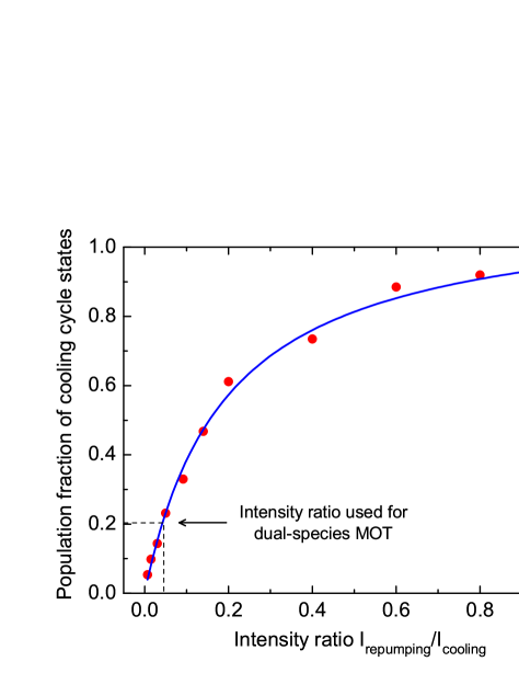
Figure 14 shows the fraction of atoms in the 40K-MOT (circles) which populate the states or (i.e. the cooling cycle states, see Fig. 2) as a function of the intensity ratio between repumping and cooling light. In the experiment, the cooling light power was fixed to 18 mW per MOT beam, and the repumping detuning was . The graph was recorded as follows. The absolute population of the states and was measured by simultaneously switching off both the repumping and cooling light of the 40K-MOT 600 before taking the image (with the imaging beam being near-resonant with the -transition). During the 600 time delay, all excited atoms relax to one of the ground states. For the used detunings and intensities of the MOT-beams of the excited atoms occupy the state and thus relax to the ground state , which is imaged. Therefore, the image approximately yields the sum of the populations of the states and . The total population of all states (i.e. the total number of trapped atoms) was measured as described in the previous paragraph.
The curve in Fig. 14 is increasing with increasing ratios and it saturates for high ratios. For the ratio about of the 40K-MOT atoms occupy the cooling cycle states. For this ratio the fluorescence emitted by the 40K-MOT is found to be maximum. For the ratio , which is used in the experiment, only of the atoms occupy the cooling cycle states. Atom losses due to light-induced collisions are thus minimized.
The solid curve in Fig. 14 shows a fit of the experimental data, based on a simple model, assuming 40K to be a four-level atom (with the states , , and ). Einstein’s rate equations yield that the curve obeys the law , with the fitting parameters and , which depend on the transition probabilities and the used intensities and detunings.
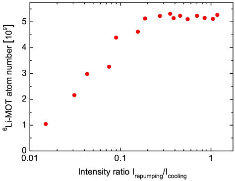
Figure 15 shows the dependence of the 6Li-MOT atom number on the intensity ratio between repumping and cooling light for the repumping detuning and a constant cooling light power of 11 mW per MOT beam. In contrast to Figure 13, the curve does not have a maximum but rather increases with increasing and saturates. This behavior is a result of the important contribution of the repumping light to the cooling process, particular to 6Li, as it has an unresolved excited state hyperfine structure.
In a dual-species MOT, inelastic collisions between atoms of the two different species can occur and represent important loss mechanisms. Previous studies have shown that the principal loss mechanisms for heteronuclear collisions in dual-species MOTs involve one ground-state and one excited atom of different species SchEng99 ; TelGar01 . Such atom pairs can undergo radiative escape or fine-structure changing collisions WeiZim03 . Both these loss processes require the two atoms to approach each other sufficiently close such that a large enough interaction energy is gained to make the atoms leave the trap. The long-range behavior of the scattering potentials determines if the atoms can approach each other sufficiently. For LiK, the scattering potentials for a singly-excited heteronuclear atom pair are all attractive for the case where the K atom is excited and all repulsive for the case where the Li atom is excited BusAch87 . As a consequence, a ground-state K atom and an excited Li atom repel each other and are prevented from undergoing inelastic collisions (optical shielding). Inelastic collisions involving singly-excited heteronuclear atom pairs thus always contain an excited K atom. In order to minimize the rate of heteronuclear collisions in the LiK-MOT, the density of excited K atoms must therefore be reduced. Furthermore, the atomic density in the trap as well as the relative speed of the colliding atoms, i.e. the temperature of the cloud, need to be minimized.
In our 6Li-40K dual-species MOT the following strategy is applied in order to minimize inelastic heteronuclear collisions. First the use of very low magnetic field gradients (8 G/cm), which decreases the atomic densities ( atoms/cm3 and atoms/cm3). Second, low intensities in the repumping light for both, 6Li and 40K, are used in order to decrease the number of excited atoms. Decreasing the number of excited 6Li atoms here a priori serves to decrease the temperature of the 6Li-cloud. Since that is much larger than the temperature of the 40K-cloud, the relative speed of two colliding atoms and thus the collision rate can be efficiently decreased by minimizing the temperature of the 6Li-cloud. Finally a small mutual influence of the MOTs is obtained: the atom numbers in the MOTs decrease by % in the 6Li-MOT and % in the 40K-MOT due to the presence of the other species.
The importance of decreasing the magnetic field gradients in order to minimize the heteronuclear collision rate in the dual-species MOT is demonstrated in Fig. 16 (a), which depicts the effect of the 6Li-MOT on the 40K-MOT atom number when a two-times larger magnetic field gradient (16 G/cm) is used. At this gradient the atomic density in the 6Li-MOT is by a factor of 4 larger than at the gradient used for the optimized MOT. In the experiment, the 40K-MOT was intentionally reduced in size (by decreasing the 2D-MOT flux) to ensure a better inclosure in the 6Li-MOT. The curve shows that % of the 40K-MOT atoms leave the trap due to the enhanced heteronuclear collisions. Using a low magnetic field gradient is therefore helping significantly to decrease the heteronuclear collisions.
In the following we determine the trap loss coefficients for the (optimized) dual-species MOT in order to quantify the heteronuclear collisions. The rate equation for the atom number in a dual-species MOT (with species and ) reads SchEng99
| (13) |
where is the loading rate, the trap loss rate due to collisions with background gas atoms and the local atomic densities. and denote the cold collision trap loss coefficients for homo- and heteronuclear collisions, respectively. and are determined from the loading and decay curves of the single-species MOTs. The obtained values for are given in Tab. 3 and is found to be s-1. The homonuclear trap loss coefficients are determined from the steady state atom numbers in single-species operation using the measured density profiles. For the experimental conditions indicated in Tab. (3), we obtain
| (14) | |||||
| (15) |
The determination of the heteronuclear trap loss coefficients for the optimized dual-species configuration would require the knowledge of the mutual overlap of the MOTs, which is difficult to estimate when absorption images are taken only along one direction. We therefore choose a configuration, which makes the determination of less dependent on assumptions about the mutual overlap (but which does not change the value of ). We reduce the atom flux of species , in order to decrease the spatial extension of the trapped cloud of species and to place it in the center of the cloud of species . A video camera which records the fluorescence of the MOTs from a different direction than that of the absorption imaging verifies that this configuration is indeed achieved. Then, in Eq. (13) it is . Comparing the steady-state atom numbers for the different configurations then yields
| (16) | |||||
| (17) |
for the experimental conditions indicated in Tab. (3). Comparing all four trap loss coefficients, the dominant is (Eq. (14)) for light-induced homonuclear 6Li-6Li collisions. This is a consequence of the large temperature of the 6Li-MOT and the unresolved hyperfine structure of 6Li which prohibits the creation of a dark MOT, leading to a large excited state population. The much smaller homonuclear trap loss coefficient for 40K (Eq. (15)) is consistent with Fig. 13 which shows that, for 40K, small repumping intensities are favorable. The heteronuclear trap loss coefficients (Eqs. (16) and (17)) are also much smaller than , indicating that our applied strategy for decreasing the heteronuclear collisions is good. In the Amsterdam group the heteronuclear trap loss coeffiecients were found by a factor of about 2 larger than ours Tie09 . A dark SPOT MOT has been implemented in order to reduce the excited state population of the 40K atoms. In the next paragraph we show, however, that it is also important to reduce the excited state population of the 6Li atoms.
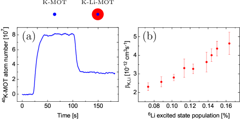
Figure 16 (b) depicts the dependence of the trap loss coefficient on the relative excited state population of the 6Li atoms. The graph was obtained by recording the influence of the 6Li-MOT on the 40K-MOT as the power of the 6Li-MOT beams was varied. For each power it was verified that the 40K-MOT was placed in the center of the 6Li-MOT and the atomic density of the 6Li-MOT was recorded. In the experiment a magnetic field gradient of 16 G/cm was used. The central atomic density of the 6Li-MOT was found to be approximately constant, when the power was varied ( atoms/cm3). The relative excited state population for a given beam power was estimated using Einstein’s rate equations. In addition the variation of the excited state population was measured by recording the fluorescence emitted by the 6Li-MOT and by measuring the number of captured atoms. The latter changed by a factor of 1.5 in the considered range of beam powers. The graph in Fig. 16 (b) shows that the trap loss coefficient increases by more than a factor of 2 as the relative excited state population is increased from % to %. The error bars shown in the figure refer to statistical errors. The uncertainty due to systematic errors is estimated to be %. The significant increase of demonstrates the importance of minimizing the number of excited 6Li atoms (and not only that of the excited 40K atoms). One reason for this increase is the increase of temperature of the 6Li-MOT, which changes from mK to mK when the beam power is increased. Another reason could be the occurence of collisions involving doubly-excited Li*K* atom pairs, the rate of which increases with the excited state populations. The scattering potentials for these collisions are known to be of a long-range, as they scale with the internuclear separation as MarSad99 , whereas they scale as for collisions involving a singly-excited heteronuclear atom pair DerJoh02 ).
5 Conclusions
We have produced a dual-species magneto-optical trap for fermionic 6Li and 40K with large atom numbers. Two strategies have been applied in order to achieve this result. First, the dual-species MOT is placed in an ultra-high vacuum environment, being continuously loaded from cold atomic beams. The atomic beams originate from separate atom sources—a Zeeman slower for 6Li and a 2D-MOT for 40K—which both yield a large flux of cold atoms. Second, the homo- and heteronuclear collisions have been minimized by using small magnetic field gradients and low light powers in the repumping light. The atom loss in each MOT due to the presence of the other species decreases by only 4% (6Li) and 10% (40K) due to the heteronuclear collisions.
We have given a detailed description of the implemented apparatus, which we hope serves as a guideline for the construction of next generation experiments with fermionic 6Li and 40K.
The produced dual-species MOT represents the starting point for the production of a large-atom number quantum degenerate Fermi-Fermi mixture. The atoms trapped in the dual-species MOT have already been transferred into the magnetic trap and magnetically transported to the science chamber with large optical access and low background pressure. The large depth of magnetic traps as compared to optical traps allows for a large transfer efficiency, leading to smaller losses of atoms. In the science cell, the dual-species cloud will be evaporatively cooled in a plugged magnetic trap to quantum degeneracy and then transferred into an optical trap for investigation.
Acknowledgements.
The authors acknowledge support from ESF Euroquam (FerMix), SCALA, ANR FABIOLA, Région Ile de France (IFRAF), ERC Ferlodim and Institut Universitaire de France. A.R. acknowledges funding from the German Federal Ministry of Education and Research and D.R.F. from Fundação para a Ciência e Tecnologia (FCT) through grant SFRH/BD/68488/2010 and from Fundação Calouste Gulbenkian.Appendix A Tapered Amplifier Mounts
We developed compact support designs for our tapered amplifier chips, in order to minimize the costs of the laser sources of our experimental setup. The TAs are commercial semiconductor chips which are mounted on homemade compact mechanical supports with nearly no adjustable parts. The support designs allow for an easy installation process, which does not require any gluing or the help of micrometric translation stages for the alignment of the collimation optics, as that can be accomplished by free hand. Furthermore, the design minimizes the heat capacity of the support and the produced temperature gradients, allowing for a quick temperature stabilization that makes the TAs quickly operational after switch-on. The temperature stabilization is accomplished using a Peltier element (Roithner Lasertechnik GmbH, ref. TEC1-12705T125) connected to a PID control circuit. The heat of the chip is dissipated via an aluminum base plate which is economically cooled by air rather than running water (the base plate reaches a maximum temperature of 28∘C for diode currents of 2A).
The commercial TA chips are sold on small heat sinks which have different dimensions for the two different wavelengths. We thus had to design slightly different supports for the Li- and K-TAs, which are both schematically shown in Fig. 17.
For lithium the semiconductor chip (Toptica, ref. TA-670-0500-5) is delivered on a heat dissipation mount of type “I”. It is placed between two axially aligned cylindrical lens tubes (CL1 and CL2 in Fig. 17 (a)), each of which containing an aspheric collimation lens of focal length 4.5 mm (Thorlabs, ref. C230TME-B). The support of the tubes and the chip are precisely machined such that the chip’s output beam falls on the center of the respective collimation lens (CL2 in Fig. 17 (a)). The tubes are supported by cylindrically holed tightenable hinges in which they can move only longitudinally, along the direction of the amplified laser beam. This restriction of the tube’s motion facilitates the alignment of the collimation lenses. The support design does not allow for a transverse alignment of the collimation lenses. Since this alignment is not very critical for the performance of the TA, we found it needless to allow this degree of freedom and relied on precise machining (possible imperfections could be compensated utilizing the mechanical play of the large attachment screw holes of the commercial heat sinks of the chips). When tightened by a screw, the hinges fix the position of the tubes. Since the tightening applies a force perpendicular to the longitudinal direction, it does not move the tubes along this (critical) direction. They might only move slightly along the transverse direction, which does not affect the final performance of the TA.
For potassium, the semiconductor chip (Eagleyard, ref. EYP-TPA-0765-01500-3006-CMT03-0000) is delivered on a heat dissipation mount of type “C”. Placing this mount between two hinges as for the case of lithium is less convenient since the heat dissipation mount has to be attached by a screw in the longitudinal direction which requires access from one side. Therefore one hinge is replaced by a rail which guides a parallelepipedically formed mount for the second (output) collimation lens (CL4 in Fig. 17 (b)). The motion of this mount is also fixed by tightening a screw applying forces perpendicular to the rail direction, which does not move the collimation lens along the critical longitudinal direction. For all our TAs, the positioning of the collimation lenses never had to be adjusted again once they were aligned.
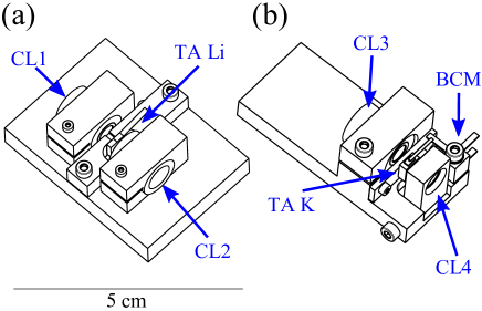
The commercial heat dissipation mount of the potassium chip is inconvenient for a simple powering of the chip. The very fragile gold wire, which has to be connected to the negative source of the current supply, has to be protected by a mechanical support before being connected to a cable. Therefore we soldered it to a blade connector that is fixed by an isolated plastic mount (BCM Fig. 17 (b)) and which is connected to the current supply. To avoid an overheating of the chip during the soldering process we permanently cooled the gold wire by blowing cold dry air from a spray can on it.
The output beams of the TA chips are astigmatic and thus require additional collimation. The choice of the collimation optics needs to be adapted to the specifications of the subsequent optical fiber, which in our case requests a collimated circular Gaussian beam of 2.2 mm 1/e2-diameter for optimum coupling efficiency. The mode-matching was found optimum for a pair of lenses consisting of one spherical lens (with f=15 cm for Li and f=4 cm for K) and a cylindrical lens (with f=8 cm for Li and f=2.54 cm for K), which are placed outside the TA’s housing. The cylindrical lenses are supported by rotatable mounts, in order to facilitate the mode-matching into the fibers. For all our TAs we achieve fiber-coupling efficiencies larger than 50% (Li) and 60% (K).
When injected with 20 mW, the Li-TAs yield an output power of 500 mW at 1 A driving current and the K-TAs yield an output power of 1500 mW at 2.5 A driving current. In order to increase the lifetime of the chips, we limit the driving currents to smaller values and we switch the chips on only for periods of experimentation. When switched on, the TAs quickly reach a stable functioning (usually within 10 min) due to the compactness of the mechanical support, which allows for a quick temperature stabilization.
References
- [1] M. Inguscio, W. Ketterle, and C. Salomon, editors. Proceedings of the International School of Physics Enrico Fermi on Ultracold Fermi Gases, Bologna, Italy, 2006. Societa Italiana di Fisica.
- [2] S. Giorgini, L. P. Pitaevskii, and S. Stringari. Theory of ultracold atomic fermi gases. Rev. Mod. Phys., 80:1215, 2008.
- [3] R. P. Feynman. Simulating physics with computers. Int. J. Theor. Phys., 21:467, 1982.
- [4] A. F. Ho, M. A. Cazalilla, and T. Giamarchi. Quantum simulation of the hubbard model: The attractive route. Phys. Rev. A, 79:033620, 2009.
- [5] D. S. Petrov, G. E. Astrakharchik, D. J. Papoular, C. Salomon, and G. V. Shlyapnikov. Crystalline phase of strongly interacting fermi mixtures. Phys. Rev. Lett., 99:130407, 2007.
- [6] M. M. Forbes, E. Gubankova, W. V. Liu, and F. Wilczek. Stability criteria for breached-pair superfluidity. Phys. Rev. Lett., 94:017001, 2005.
- [7] J. Levinsen, T. G. Tiecke, J. T. M. Walraven, and D. S. Petrov. Atom-dimer scattering and long-lived trimers in fermionic mixtures. Phys. Rev. Lett., 103:153202, 2009.
- [8] J. Deiglmayr, A. Grochola, M. Repp, K. Mörtlbauer, C. Glück, J. Lange, O. Dulieu, R. Wester, and M. Weidemüller. Formation of ultracold polar molecules in the rovibrational ground state. Phys. Rev. Lett., 101:133004, 2008.
- [9] K.-K. Ni, S. Ospelkaus, M. H. G. de Miranda, A. Pe’er, B. Neyenhuis, J. J. Zirbel, S. Kotochigova, P. S. Julienne, D. S. Jin, and J. Ye. A high phase-space-density gas of polar molecules.
- [10] M. Aymar and O. Dulieu. Calculation of accurate permanent dipole moments of the lowest states of heteronuclear alkali dimers using extended basis sets. J. Chem. Phys., 122:204302, 2005.
- [11] T. G. Tiecke, M. R. Goosen, A. Ludewig, S. D. Gensemer, S. Kraft, S. J. J. M. F. Kokkelmans, and J. T. M. Walraven. Broad feshbach resonance in the 6Li-40K mixture. Phys. Rev. Lett., 104:053202, 2010.
- [12] A. Ridinger, S. Chaudhuri, T. Salez, N. Bouloufa, L. Pruvost, O. Dulieu, F. Chevy, and C. Salomon. Photo-associative creation of excited 6Li-40K molecules in a magneto-optical trap. 2011.
- [13] M. Taglieber, A.-C. Voigt, F. Henkel, S. Fray, T. W. Hänsch, and K. Dieckmann. Simultaneous magneto-optical trapping of three atomic species. Phys. Rev. A, 73:011402, 2006.
- [14] F. M. Spiegelhalder, A. Trenkwalder, D. Naik, G. Kerner, E. Wille, G. Hendl, F. Schreck, and R. Grimm. All-optical production of a degenerate mixture of 6Li and 40K and creation of heteronuclear molecules. Phys. Rev. A, 81:043637, 2010.
- [15] Tobias Tiecke. Ph.D. thesis. University of Amsterdam, 2009.
- [16] M. Greiner, I. Bloch, T. W. Hänsch, and T. Esslinger. Magnetic transport of trapped cold atoms over a large distance. Phys. Rev. A, 63:031401, 2001.
- [17] U. Eismann, F. Gerbier, C. Canalias, G. Trénec, J. Vigué, Frédéric Chevy, and Christophe Salomon. An all-solid-state laser source at 671 nm for cold atom experiments with lithium. 2011.
- [18] K. A. Yakimovich and A. G. Mozgovoi. Experimental investigation of the density and surface tension of molten lithium at temperatures up to 1300 k. High Temp., 38:657, 2000.
- [19] G. Ferrari, M.-O. Mewes, F. Schreck, and C. Salomon. High-power multiple-frequency narrow-linewidth laser source based on a semiconductor tapered amplifier. Opt. Lett., 24:151, 1999.
- [20] M.-O. Mewes, G. Ferrari, F. Schreck, A. Sinatra, and C. Salomon. Simultaneous magneto-optical trapping of two lithium isotopes. Phys. Rev. A, 61:011403, 1999.
- [21] Z. Hadzibabic, S. Gupta, C. A. Stan, C. H. Schunck, M. W. Zwierlein, K. Dieckmann, and W. Ketterle. Fiftyfold improvement in the number of quantum degenerate fermionic atoms. Phys. Rev. Lett., 91:160401, 2003.
- [22] T. G. Tiecke, S. D. Gensemer, A. Ludewig, and J. T. M. Walraven. High-flux two-dimensional magneto-optical-trap source for cold lithium atoms. Phys. Rev. A, 80:013409, 2009.
- [23] W. D. Phillips and H. Metcalf. Laser deceleration of an atomic beam. Phys. Rev. Lett., 48:596, 1982.
- [24] H. J. Metcalf and P. van der Straten. Laser cooling and trapping. Springer, Berlin, 1999.
- [25] A. Joffe, W. Ketterle, A. Martin, and D. E. Pritchard. Transverse cooling and deflection of an atomic beam inside a zeeman slower. J. Opt. Soc. Am. B, 10:2257, 1993.
- [26] N. F. Ramsey. Molecular Beams. Oxford University Press, Oxford, 1986.
- [27] C. B. Alcock, V. P. Itkin, and M. K. Horrigan. Vapour pressure equations for the metallic elements: 298-2500K. Can. Metall. Q., 23:309, 1984.
- [28] K. Dieckmann, R. J. C. Spreeuw, M. Weidemüller, and J. T. M. Walraven. Two-dimensional magneto-optical trap as a source of slow atoms. Phys. Rev. A, 58:3891, 1998.
- [29] J. Schoser, A. Batär, R. Löw, V. Schweikhard, A. Grabowski, Yu. B. Ovchinnikov, and T. Pfau. Intense source of cold Rb atoms from a pure two-dimensional magneto-optical trap. Phys. Rev. A, 66:023410, 2002.
- [30] J. Catani, P. Maioli, L. De Sarlo, F. Minardi, and M. Inguscio. Intense slow beams of bosonic potassium isotopes. Phys. Rev. A, 73:033415, 2006.
- [31] S. Chaudhuri, S. Roy, and C. S. Unnikrishnan. Realization of an intense cold Rb atomic beam based on a two-dimensional magneto-optical trap: Experiments and comparison with simulations. Phys. Rev. A, 74:023406, 2006.
- [32] A. M. Steane, M. Chowdhury, and C. J. Foot. Radiation force in the magneto-optical trap. J. Opt. Soc. Am. B, 9:2142, 1992.
- [33] A. Derevianko, W. R. Johnson, M. S. Safronova, and J. F. Babb. Radiation force in the magneto-optical trap. Phys. Rev. Lett., 82:3589, 2002.
- [34] M. S. Santos, P. Nussenzveig, L. G. Marcassa, K. Helmerson, J. Flemming, S. C. Zilio, and V. S. Bagnato. Simultaneous trapping of two different atomic species in a vapor-cell magneto-optical trap. Phys. Rev. A, 52:R4340.
- [35] U. Schlöder, H. Engler, U. Schünemann, R. Grimm, and M. Weidemüller. Cold inelastic collisions between lithium and cesium in a two-species magneto-optical trap. Eur. Phys. J. D, 7:331, 1999.
- [36] G. D. Telles, W. Garcia, L. G. Marcassa, V. S. Bagnato, D. Ciampini, M. Fazzi, J. H. Müller, D. Wilkowski, and E. Arimondo. Trap loss in a two-species Rb-Cs magneto-optical trap. Phys. Rev. A, 63:033406, 2001.
- [37] J. Goldwin, S. B. Papp, B. DeMarco, and D. S. Jin. Two-species magneto-optical trap with 40K and 87Rb. Phys. Rev. A, 65:021402, 2002.
- [38] V. Dribinski, A. Ossadtchi, V. A. Mandelshtam, and H. Reisler. Reconstruction of Abel-transformable images: The Gaussian basis-set expansion Abel transform method. Rev. Sci. Instrum., 73:2634, 2002.
- [39] M. Weidemüller and C. Zimmermann. Interactions in Ultracold Gases. Wiley-VCH, Weinheim, 2003.
- [40] B. Bussery, Y. Achkar, and M. Aubert-Frécon. Long-range molecular states dissociating to the three of four lowest asymptotes for the ten heteronuclear diatomic alkali molecules. Chem. Phys., 116:319, 1987.
- [41] M. Marinescu and H. R. Sadeghpour. Long-range potentials for two-species alkali-metal atoms. Phys. Rev. A, 59:390, 1999.