e+source_ERL_appb-v4a.dvi keepcomments
2 Fakultät für Physik, Ludwig-Maximilians Universität, 85748 Garching, Germany
3 Max-Planck-Institut für Quantenoptik, 85748 Garching, Germany
High-Intensity and High-Brightness Source of Moderated Positrons Using a Brilliant Beam
Abstract
Presently large efforts are conducted towards the development of highly brilliant beams via Compton back scattering of photons from a high-brilliance electron beam, either on the basis of a normal-conducting electron linac or a (superconducting) Energy Recovery Linac (ERL). Particularly ERL’s provide an extremely brilliant electron beam, thus enabling the generation of highest-quality beams. A 2.5 MeV beam with an envisaged intensity of photons , as ultimately envisaged for an ERL-based -beam facility, narrow band width (), and extremely low emittance (mm2mrad2) offers the possibility to produce a high-intensity bright polarized positron beam. Pair production in a face-on irradiated W converter foil (200 m thick, 10 mm long) would lead to the emission of (fast) positrons per second, which is four orders of magnitude higher compared to strong radioactive 22Na sources conventionally used in the laboratory. Using a stack of converter foils and subsequent positron moderation, a high-intensity low-energy beam of moderated positrons can be produced. Two different source setups are presented: a high-brightness positron beam with a diameter as low as 0.2 mm, and a high-intensity beam of moderated positrons per second. Hence, profiting from an improved moderation efficiency, the envisaged positron intensity would exceed that of present high-intensity positron sources by a factor of 100.
1 Introduction
Currently large efforts are devoted world-wide to the development of highly brilliant beams. In such a facility, the beam with low emittance is created by inverse Compton scattering of photons, which are provided by a high-power laser, with an ultra-relativistic electron beam either provided by a normal conducting electron linac or an Energy Recovery Linac (ERL). Until about 2018, it is envisaged to generate a beam with an intensity of -photons per second (the term intensity is used throughout this paper in units of ’ number of particles or photons per second’) and the energy of 2.5(5) MeV Haj08 ; Hay10 . Using a brilliant beam, positron-electron pairs can be produced in a suitable target by pair production. A well designed positron source would hence allow to create a moderated positron beam of high intensity and/or high brightness. In addition, the brightness can be further enhanced by positron remoderation.
Positron beams are usually generated by using emitters such as 22Na and a thin W foil or solid Ne as moderator with an intensity of about moderated positrons per second. At large-scale facilities, such as electron linacs or nuclear reactors, positron beams are created with higher intensity by pair production. At present, the NEutron induced POsitron source MUniCh (NEPOMUC) provides the world highest intensity of moderated positrons per second Hug08b .
In general, various sources used for pair production such as bremsstrahlung targets at linacs, fission ’s at reactors or the de-excitation of nuclear states emit radiation isotropically. For this reason, at present linac or reactor-based positron sources, the large area of the converter and positron moderators is the main drawback for improving the brightness of the positron beam. Consequently, one can greatly benefit from a low-emittance beam, which allows the adaptation of a converter and positron moderator in an efficient positron source geometry. A brilliant 2.5 MeV beam with an envisaged intensity of photons would allow to create a positron beam whose intensity exceeds that of present high-intensity positron sources by more than two orders of magnitude.
In this paper, various positron source designs and the relevant features are discussed. In particular, two layouts, which provide a high-brightness or a high-intensity positron beam, are presented and quantitatively compared with the NEPOMUC beam.
2 High-brilliant sources
High-quality energetic photon beams are versatile tools for a wide range
of physics studies, ranging from precisely probing nuclear properties
and processes to serving as a starting point for secondary sources such
as neutrons or positrons.
In general, beams are produced via Compton back-scattering of
laser photons from a relativistic electron beam.
The presently world-leading facility for photonuclear physics is the
High-Intensity -ray Source (HIS) at Duke University (USA).
It uses the Compton back-scattering of photons, provided by a high-intensity
Free-Electron Laser (FEL), in order to produce a brilliant beam.
The intensity in the energy range between 1 and 3 MeV amounts
to photons with a band width of about 5 Wel09 .
Based on a normal-conducting electron linac, the brilliant Mono-Energetic
Gamma-ray (MEGa-ray) facility at Lawrence Livermore National Laboratory (USA) will
yield already in 2012 a -intensity of photons , with an
energy band width of Bar10megaray .
Using similar accelerator technology, at the upcoming Extreme Light Infrastructure -
Nuclear Physics (ELI-NP) facility in Bucharest, until 2015 a beam will
become available, providing about the same -intensity and band width in the
energy range of 1-19 MeV ELI-NP10 .
At present, great efforts are also invested all over the world to realize highly
brilliant beams based on the Energy Recovery Linac (ERL) technology.
The Energy Recovery Linac (ERL) is a new type of superconducting electron accelerator
that provides a high-brilliant, high-intensity electron beam.
The main components of an ERL are an electron injector, a superconducting linac,
and an energy recovery loop.
After injection from a high-brilliant electron source, the electrons are
accelerated by the time-varying radio-frequency field of the superconducting linac.
The electron bunches are transported through a recirculation loop and are re-injected
into the linac during the decelerating RF phase of the superconducting cavities.
So the beam dump has to take only a small fraction of the beam energy.
In this way, the energy is recycled very efficiently and re-used to accelerate
a new bunch of electrons.
ERL’s create high-energy, high-brilliant beams by Compton
back-scattering of photons from high-energy (0.1-5 GeV) electrons,
recirculating the photons in a very high-finesse cavity with MW power.
ERL technology has been pioneered at Cornell University (together with the
Thomas Jefferson National Laboratory) Bil10a ; Bil10b ; liepe10 ,
where an ERL is presently constructed for a 5 GeV, 100 mA electron beam.
At the KEK accelerator facility in Japan, an ERL project is presently pursued
aiming at a beam with an intensity of photons Haj08 ; Hay10 .
In Germany, a high-current and low-emittance demonstrator ERL facility (BERLinPro)
is developed at the Helmholtz Zentrum Berlin Jan10 .
Three different operation modes are conducted: high-flux mode,
high-coherence (brilliance) mode, and a short-pulse mode Bil10a ; Bil10b ; Hay10 .
For our purpose of positron production, the high-flux mode is of particular interest.
Moreover, the facility can be optimized to the specific needs of the intended
application. When, e.g., as in the present case aiming at the production of a high-brightness positron beam,
a small beam spot size and low beam divergence is
more important than the superb energy band width provided by an ERL.
The ultimately envisaged photon intensity is photons in an energy range of
0.5-20 MeV.
Such a facility would provide a brilliant pulsed (ps pulse length)
beam with a narrow band width of about and a low emittance
of .
3 Positron production by a high-brilliant beam
3.1 Principle of the positron source
There are two fundamentally different setups for the creation of a moderated positron beam using a brilliant beam. Either the -positron-electron converter and the positron moderator are separate components, or the converter is used as positron moderator as well, and hence the moderated positrons are extracted directly from the converter surface. The production and subsequent moderation in the same component is called self-moderation. In order to create a bright positron beam, a moderator should be used with high efficiency and narrow band width of the emitted positrons. However, the choice of the applied moderator material strongly depends on the final source layout. Various designs specifically suited for brilliant beams and the respective features are presented in Section 3.2.
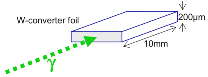
The conversion into positron-electron pairs takes place in a material with high nuclear charge , such as Pt or W (also suitable moderator materials), since the pair production cross section increases approximately proportional to . At a energy of 2.5 MeV, the pair production cross section for Pt and W amounts to 2.386 and 2.713 barn/atom, respectively. In addition, the converter material should have a high melting temperature due to the high local heat dissipation. The optimum thickness of a single converter foil with highest amount of emitted positrons is in the range of 0.4-0.5 g/cm2 Kru90 . In order to create free (fast) positrons, one could simply choose a thin W converter foil (density 19.35 g/cm3, e.g., 200 m thick, 10 mm long), which is irradiated by the beam on the face side -as sketched in Figure 1- leading to a absorption of about 55.4 . The amount of free fast positrons can be calculated, considering the pair production cross section and the probability for fast positron emission from a 200 m thick W foil, which amounts to 20 Kru90 . Thus, a beam with a intensity of photons would lead to the emission of (fast) positrons per second from an area of about 2 mm2. The positron intensity of this source would be four orders of magnitude higher than that from strong radioactive 22Na sources (2 GBq) conventionally used in the laboratory.
As shown below, the fraction of moderated and emitted positrons can be enhanced by using a stack of several converter foils. Suited materials for positron moderation are metals with negative positron work function such as Pt ( eV Hug02d ) and W ( eV Coleman2000 ) or solid rare gases Mil86 . The moderation efficiency of W is known to be higher than that of Pt and amounts to about Lyn85 . However, depending on the surroundings, Pt might become more reliable during operation due to the in-situ annealing of radiation-induced defects. Hug04a Solid rare gas moderators exhibit higher moderation efficiencies, but the bandwidth of the resulting positron beam is larger due to the emission of epithermal, i.e., not fully thermalized positrons. The moderation efficiency was measured with a 50 m solid Ne film on top of a 22Na source and amounts to Mil86 . The energy spread of the Ne moderated positrons was found to be 0.58 eV, and hence, about one order of magnitude worse than that from a W moderator Mil86 . In general, the comparison of the moderation efficiencies is often difficult, since it does not only depend on the primary positron spectrum, but, even more importantly, on the used moderator geometry. For this reason, efforts were done to increase the yield of moderated positrons by optimizing the source-moderator layout. In the following, the moderation efficiency is defined as the number of moderated positrons in the slow positron beam divided by the number of produced (fast) positrons in the converter. In addition, remoderation of the positron beam would lead to a further enhancement of the beam brightness (see e.g. Mil80c ; Pio08 ).
3.2 Geometry of the converter-moderator setup
An overview of two basic layouts specifically suited for a brilliant beam-induced positron source, with three different configurations each, is given in Figure 2. In the first layout (1) the -positron-electron conversion and the positron moderation take place in the same component (self-moderation). The second one (2) consists of the converter and a separated positron moderator.
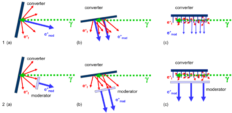
In the layout (1), the application of a metallic converter and moderator seems to be most convenient due to the high local heat load. Therefore, a converter material, such as W or Pt, should be applied in order to operate the converter reliably. In general, using the geometry (2), the moderator has to be mounted as close as possible to the converter in order to increase the solid angle for positron moderation. In this layout, solid rare gases can be applied, e.g., a thin layer of Ne frozen on top of a Be foil, which would lead to a higher moderation efficiency, but also to a higher band width of the moderated positron beam and a larger beam diameter.
(a) The tiniest beam spot, and probably the highest brightness, is achieved using layout 1(a), since the diameter of the moderated positron beam is barely larger than the interaction area defined by the beam. The usage of a separate Ne moderator (setup 2(a)) would increase the moderation efficiency at the expense of a lower solid angle for the positron irradiation.
(b) The grazing incident beam shown in 1(b) and 2(b) would increase the total rate of produced positrons, but the positron beam area would be that of a largely elongated ellipse with lower brightness compared to versions 1(a) and 2(a).
(c) In the layouts 1(c) and 2(c), the converter consists of a stack of thin W or Pt foils, which would lead to a very efficient absorption of the beam. The positron production and emission rate can be improved with the number of foils, i.e., the cumulated thickness of the converter material. Due to the narrow beam, short foils could be used facilitating the extraction of the moderated slow positrons. In version 1(c), a suitable electrical acceleration field has to be applied in order to extract the moderated positrons since they are emitted perpendicular to the moderator surface. This challenge will be overcome in version 2(c), where a moderator can be placed close to the converter. The beam extraction could also be performed perpendicular to the plane of projection for the setups 1(c) and 2(c). However, similar to the layouts 1(b) and 2(b), the cross section of the resulting positron beam would be largely elongated in one dimension.
3.3 The high-brightness and the high-intensity positron beam
In summary, we propose to focus on two most promising source setups, which should be realized in a brilliant beam facility: The first one would generate a high-brightness (HB), and the second one a high-intensity (HI) moderated positron beam.
The HB source geometry corresponds very much to the layout 1(a) in Figure 2. In the thin layer limit, i.e., low absorption, the production rate of (fast) positrons can be approximated by with the intensity and the W atom density . For a W foil with a thickness of =250 m, the fraction of emitted positrons amounts to with respect to the number of produced positrons and is much higher for thinner foils, e.g., for =10 m Kru90 . Hence, using a 250 m W foil in back reflexion geometry for the HB source, about 20 of the produced positrons can contribute to the emission of moderated positrons. The fraction of fast positrons with a mean energy of 750 keV stopped in a surface layer of 50 nm amounts to . According to the positron diffusion length in W of 135 nm Veh83 , it is assumed that almost all positrons thermalized in the 50 nm surface layer reach the surface. Accounting for losses at the surface due to Positronium formation , and trapping in surface states , the positron probability to be emitted as a moderated positron is . This consideration and the value for is in agreement with the moderation efficiency experimentally determined for W(100) using a 22Na source with an according mean positron energy of 200 keV Lyn85 . Thus, the yield of moderated positrons is calculated as . With the numbers given above, one obtains .
The positron beam diameter is slightly greater than the beam diameter. Its increase is of the order of the mean positron range of about 0.1 mm. The positron diffusion length is about three orders of magnitude lower and hence negligible. The parameters expected for a HB positron beam are shown in Table 1. Besides the higher brightness, a major advantage of the HB source is the relatively simple setup, where an electrical extraction field has to be applied for positron acceleration.
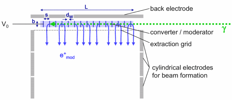
In the following, we present a more detailed source geometry for the creation of a HI positron beam. The layout of the HI source shown in Figure 3 is similar to 1(c) shown in Figure 2, and can easily be extended to the version 2(c). The converter-moderator, which is operated in the vacuum, consists of a stack of single crystalline W foils of thickness with a spacing between the foils of . The width of the W foils would be of the order of the diameter of the beam. The length of the foils (perpendicular to the drawing plane of Figure 3) can be chosen much larger than to facilitate the extraction of the moderated positrons. In order to keep the total length of the converter not too long, a ratio of :=3:1 is expected to be reasonable for a good enough beam extraction by an electric field. Such a converter can be either set up by using W(100) foils clamped between small W holders, or the whole component is cut out from a long W single crystal using a laser cutter or spark erosion. Tilting of the equally spaced foils would increase the effective absorption length in the foils, but –keeping the ratio : constant– the spacing by the same amount as well. Hence, at a given total absorption length, the number of foils would decrease, and the length of the whole converter would not change.
In the following, the arrangement with parallel foils, i.e., perpendicular to the beam, is presented. The advantages of this setup are higher mechanical stability, lower heat input per foil, better usage of reflected fast positrons, and higher solid angle for the individual foils with respect to the neighboring ones, leading to a higher efficiency to produce moderated positrons.
The converter-moderator block is aligned in direction of the beam which interacts with the W foils by pair production. In contrast to the primary produced fast positrons, the moderated positrons are emitted perpendicular to the W(100) surface. Since their primary kinetic energy amounts to Jac90 , an electrical extraction field is needed, which is provided by the back electrode and the extraction grid as shown in Figure 3. The potential applied at the converter-moderator block defines the final kinetic energy of the positron beam . The beam should be extracted in a zero magnetic field in order to maintain the low primary divergence and the high grade of polarization of the moderated positron beam.
In order to estimate the resulting moderated positron yield from the production rate , we first consider a single foil, and a two-foil arrangement in the extreme limits: A single converter foil with two surfaces emitting moderated positrons would give: . For a stack of thin foils with and for not too high total converter length, i.e., not much longer than the mean positron range, a produced positron could be stopped in any foil and has a certain probability to reach the surface. In this case, can be approximated by the constant value given above, and would just scale with the number of positron emitting surfaces : . In the second limit for , each foil would act independently, and hence, would be the sum of the producing and moderating foils with 2 surfaces each: .
In a realistic arrangement, the calculation of becomes very complicated, since each W production foil irradiates the others by positrons with a certain probability. Hence, the respective solid angles, positron attenuation, and stopping in a surface layer has to be considered. Note, that has to be calculated as function of the positron energy, which depends on the respective positron absorption length , since it might become considerably higher for low-energy positrons.
We propose a converter of parallel W foils with =200 m, a ratio of :=3:1 and hence spacing s=67 m, and . Thus, the converter length would amount to , and the cumulated thickness of the W converter material would be mm. The total absorption in the W foils would be about 87 , and consequently, the corresponding heat input due to heating of 350 W has to be dissipated by a cooling device at the converter. The total positron production rate would be . Due to the absorption, the number of produced positrons in an individual W foil would decrease with the foil number N . The yield of moderated positrons of the whole HI setup can be estimated by . The term accounts for an additional contribution of the other foils to the emission of moderated positrons of each single foil. Hence, can reach values well above 1, since becomes much larger than for low-energy positrons. Taking the numbers given for , , and , one gets . Accounting for the respective solid angles, the emitted and slowed-down positrons of the neighboring foils lead to the additional emission of moderated positrons resulting in . Hence, the positron yield can be roughly estimated and amounts to . Note, that this value can even be higher due to the contribution of reflected positrons, which are moderated, and a higher moderation efficiency of inelastically scattered positrons. Thus, compared to the HB setup, the slow-positron yield would be about 3500 times higher at the HI source, and it would exceed the intensity of the upgraded NEPOMUC Hug11x source by two orders of magnitude. Due to the much larger beam spot, which is expected to be about 400 mm2, the brightness of the HI beam would be lower than that for the remoderated beam at NEPOMUC, and more than two orders of magnitude worse than that at the HB source (see Table 1). Note, that, taking into account the longitudinal energy spread, the brightness of the HI or the HB pulsed beams (pulse length of a few ps) could be enhanced considerably by narrowing the energy width at the expense of time resolution.
Besides the considerations with respect to the positron production rate and yield of moderated positrons, other factors have to be considered as well, such as converter cooling, annealing of the moderator, and positron beam extraction. Independent of the source layout, the moderator –or the converter if it acts as moderator as well– has to be floated on a variable potential in the range of 0.01-5 kV (or even higher) in order to adapt the kinetic energy of the positrons to the experimental requirements. Additional lenses have to be mounted in front of the moderator for positron beam formation, and the positron beam should be magnetically guided to the experimental setups.
In order to estimate various positron beam parameters such as , , diameter , and brightness , we assume the availability of a brilliant beam with an intensity =1015photons , an energy of 2.5(5) MeV, and a diameter of 0.1 mm. According to Liouville’s theorem, the product of the divergence, the beam diameter, and the longitudinal component of the momentum is constant. Hence, the brightness defined as is a good figure of merit for a positron beam of intensity (particles per second) , diameter , divergence with transversal and longitudinal components of the positron energy and . Note, that this definition of is commonly used for the characterization of positron beams (see e.g. Coleman2000 ; Mil80c ; Sch88 ). However, in the literature the terms brilliance and brightness are not used in a consistent way.
Here, we assume that all moderated positrons leaving the foils are extracted, i.e., , and the kinetic energy of the positrons is set to =1 keV. All parameters are calculated for both the HB and the HI positron source as well, and summarized in Table 1. Since the HI source would provide a beam cross section, which is largely elongated in one dimension, an effective diameter of a circular shaped beam spot of the same size is given. For comparison, the values for the NEPOMUC beam and its upgrade are shown as well. As a result, using the HB source, one can expect a positron beam with a brightness, which is more than two orders of magnitude higher than that of the remoderated NEPOMUC beam. With the HI layout, the positron intensity is expected to be two orders of magnitude higher than that of the NEPOMUC upgrade. Depending on the properties of the beam, these parameters scale with the available intensity. An additional remoderation device could be used for further brightness enhancement.
| brilliant beam | |||
| NEPOMUC | HB source | HI source | |
| setup | Pt 125 m trans. | W 250 m refl. | W 2500 x 10 m refl. + trans. |
| 2.6. (5.9. | 5.7 | 1.6 | |
| 9.0 (3.0) | 8.5 | 3.0 | |
| 3.5 (5.1) | 1.5 | 1.9 | |
| 50∗ (0.15) | 2.5 | 3.0 | |
| 2.2 (1.2) | 5.0 | 5.5 | |
| 7∗ (70) | 0.2 | 23 | |
| 3.7, 5 remod. | 8.5 | 1.9 | |
| (4.1) | |||
| spin polarization | no | yes | yes |
| operation mode | continuous | pulsed (ps) | pulsed (ps) |
In general, the key features of a low-energy positron beam based either on the HB or HI layout using a high-brilliant beam would be the following:
-
•
energy: The energy of the beam can be varied in the range of a several MeV in order to maximize the positron production and emission rate as well as the yield of moderated positrons.
-
•
Band width: Due to the small band width of the beam, no unwanted ’s are produced with which do not contribute to the pair production. Therefore, the heat load compared to linac or reactor based positron sources is expected to be considerably lower.
-
•
Diameter and brightness: The intrinsic small diameter of the beam leads to an accordingly small positron beam. Dependent on the source geometry, a higher brightness of the moderated beam is expected as well.
-
•
Polarization: Using a switchable fully polarized beam, a spin-polarized positron beam can be created. Since the positron polarization is almost entirely maintained during moderation Zit79 , spin-dependent experiments may become feasible.
-
•
Time structure: The time structure provided by the pulsed beam is barely deteriorated by the moderation process since positrons thermalize very rapidly (within a few picoseconds) after production or implantation. It is expected that a smearing of the beam pulse is mainly caused by the resulting positron spectrum, different flight paths in the source and position dependent acceleration of the moderated positrons. However, the usefulness of the time structure of the beam strongly depends on the positron beam application, e.g., for coincidence techniques using lasers rather than for positron lifetime spectroscopy.
-
•
Access: The source area of the beam will be easily accessible. This would facilitate the change of the source setup considerably. For future applications, we recommend to install a source switch in order to allow a quick change from a high-brightness to a high-intensity positron beam.
-
•
Radiation field Due to the well defined relatively low energy of the beam, e.g., 2.5(5) MeV, the creation of radiation induced defects is expected to be lower than that at positron source setups using bremsstrahlung targets at linacs or rays produced at nuclear reactors. In addition, no radioactivity is created by activation.
4 Outlook and conclusion
4.1 First beam based positron sources
Great efforts are presently made to develop high-brilliant beams. Within the next years, two -beam facilities with an intensity of photons will become available. Both, the Mono-Energetic Gamma-ray (MEGa-ray) source in Livermore (commissioning starting in 2012), and the Extreme Light Infrastructure - Nuclear Physics facility (ELI-NP) planned in Bucharest (operation envisaged for 2015), designed for photons , would be suited to install a -beam based positron source, potentially exceeding the presently strongest positron source (NEPOMUC) by about a factor of three. Feasibility studies for the positron beam production, using the source layouts as presented here, can be performed in advance, and experimental data can be gained already at much lower beam intensity. It is expected that even more brilliant (ERL-based) beam facilities will become operational within the next decade with an ultimate intensity of photons and a diameter of 0.1 mm.
We propose the installation of both the HB and the HI positron source in the target area at ELI-NP. The low-energy positron beam can be transported over long distances and through bends without intensity loss or considerable deterioration of the positron beam quality as long as the positrons are guided adiabatically in a static homogeneous magnetic field. There are two main techniques to realize the homogeneous longitudinal magnetic guide field: Either solenoid coils directly mounted on the beam line or a Helmholtz-like setup of several coils with larger diameter. Additional saddle coils are required in order to compensate for transversal field components, and -metal shielding can be mounted as well. Therefore, the moderated positrons created at ELI-NP can be guided to an external experimental area if the place close to the target is limited.
After calculation of several entities such as production and emission rates of positrons for various converter materials and different geometries and simulation of positron beam trajectories, experimental data have to be gained in order to optimize the positron source setup. Such experiments can also be performed at a low-flux beam facility. Afterwards, the optimized HB and HI positron sources can be installed where brilliant beams become available at ERL’s.
In the following several aspects are considered for first experiments:
-
•
The energy dependent pair production cross section increases considerably with increasing -energy leading to a higher positron production rate. However, the slow-positron yield does not increase in an analogous manner, since the positron moderation efficiency decreases with higher energy. Therefore, the positron yield as function of energy should be determined.
-
•
Several converter geometries can be compared in order to increase the intensity and/or the brightness of the moderated positron beam. A higher mass of the converter, i.e., thicker foils and/or more foils, would lead to a higher positron production rate. An increased surface-to-volume ratio would result in a higher yield of moderated positrons. Using a separate moderator, the solid angle with respect to the converter should be maximized in order to extract as many positrons as possible.
-
•
Two setups should be compared and optimized for positron beam applications: the HB setup and the HI layout based on self-moderation or with a separated Ne moderator. For various setups the spectrum and the brightness of the slow-positron beam have to be determined experimentally.
4.2 Future applications of a high-intensity positron beam
Depending on the experimental requirements, a bright beam with a diameter of about 200 m as delivered from the HB source might be more suited than the high-intensity beam from the HI source. However, one could use an additional remoderation device to further enhance the brightness.
There are many applications, which would benefit from a strong positron source providing a high-intensity low-energy positron beam (see e.g. Hug10a ). A high positron intensity would be very advantageous for the generation of (re-)moderated positron micro-beams for all scanning beam techniques. In materials science and solid-state physics, such a micro-beam would greatly enhance the statistics for spatially resolved defect spectroscopy, using scanning positron lifetime or Doppler-broadening measurements. For the application of coincidence techniques, a high-intensity positron beam is even more important, since the measurement time would be drastically reduced and the spatial resolution would be improved as well. Such techniques are Coincident Doppler-Broadening Spectroscopy (CDBS), that allows to investigate the chemical environment of open volume defects, Age-MOmentum Correlation (AMOC), where the positron lifetime and the Doppler-shift are detected simultaneously for each annihilation event; or the determination of the Angular Correlation of Annihilation Radiation (ACAR) in order to study the electronic structure of matter. A bright intense low-energy beam would allow to further develop Positron annihilation induced Auger-Electron Spectroscopy (PAES) for spatially resolved surface analysis. In atomic physics, intense positron beams are desired, since small-diameter beams carrying a high intensity are crucial in all kinds of positron scattering experiments. For the creation of mono-energetic Positronium (Ps) beams and for the Ps- production, a high intensity of the moderated positron beam would be very helpful. This would hence allow the spectroscopy of Ps and Ps-. In addition, for fundamental experiments, the specific formation of the Ps2 molecule or even the creation of a Ps Bose-Einstein condensate would become possible.
4.3 Conclusion
With the availability of high-brilliant sources, the realization of high-intensity and high-brightness positron sources will become possible within a few years. The efforts and costs of such positron sources are expected to be not too elaborate. At a brilliant beam with an envisaged intensity of photons , a positron beam would exceed the intensity of the upgraded high-intensity positron source NEPOMUC by a factor of 100. Using the high-brightness setup, the brightness is expected to be more than two orders of magnitude higher than that of the present remoderated positron beam at NEPOMUC. In the final configuration, we recommend the implementation of two different source setups. Hence, one could choose between a high-brightness positron beam with a tiny diameter in the order of 0.2 mm or a larger high-intensity beam which provides about moderated positrons per second. The availability of such an intense positron source would greatly improve all kinds of positron beam applications in material science, solid-state, surface, and atomic physics as well as fundamental experiments using positrons or positroniums.
References
- (1) R. Hajima, N. Nakamura, S. Sakanage, Y. Kobayashi, Design study of the compact ERL, KEK-Report 2007-7, JAEA-Research 2008-032 (2008).
- (2) T. Hayakawa, N. Kikuzawa, R. Hajima, T. Shizuma, N. Nishimori, M. Fujiwara M. Seya, Nondestructive assay of plutonium and minor actinide in spent fuel using nuclear resonance fluorescence with laser compton scattering [gamma]-rays, Nucl. Instr. Meth. A 621, 695 (2010).
- (3) C. Hugenschmidt, B. Löwe, J. Mayer, C. Piochacz, P. Pikart, R. Repper, M. Stadlbauer and K. Schreckenbach, Unprecedented intensity of a low-energy positron beam, Nucl. Instr. Meth. A 593, 616 (2008).
- (4) D.H. Bilderback, J.D. Brock, D.S. Dale, K.D. Finkelstein, M.A. Pfeifer, and S.M. Gruner, Energy recovery linac (erl) coherent hard x-ray sources, New Journal of Physics 12, 035011 (2010), http://stacks.iop.org/1367-2630/12/i=3/a=035011.
- (5) D.H. Bilderback, G. Hoffstaetter, S.M. Gruner, Rd towards an energy recovery linac at sychrotron light source, Synchrotron Radiation News 6, 32 (2010).
- (6) M. Liepe, S. Belomestnykh, E. Chojnacki, Z. Conway, G. Hoffstaetter, R. Kaplan, S. Posen, P. Quigley, J. Sears, V. Shemelin, V. Veshcherevich, Latest results and test plans from the 100 mA Cornell ERL injector SCRF cryomodule, Proceedings of IPAC 10, Kyoto, Japan, May 23-28, 2010, http://accelconf.web.cern.ch/AccelConf/IPAC10/papers/wepec066.pdf
- (7) H.R. Weller, M.W. Ahmed, H. Gao, W. Tornow, Y.K. Wu, M. Gai and R. Miskimen, Research opportunities at the upgraded hi[gamma]s facility, Progr. Part. Nucl. Phys. 62, 257 (2009).
- (8) A. Jankowiak, M. Abo-Bakr, W. Anders, T. Kamps, J. Knobloch, B. Kuske, O. Kugeler, A. Matveenko, A. Meseck, A. Neumann, T. Quast, J. Rudolph, BERLinPro - a compact demonstrator ERL for high current and low emittance beams, Proceedings of LINAC 10, Tsukuba, Japan, Sept. 12-17, 2010, to appear. on http://www.JACoW.org/.
- (9) C.P.J. Barty, Development of Mega-Ray technology at LLNL, http://www.eli-np.ro/documents/eli-excom-meeting/Barty-100412-ELI-NP-LLNL-MEGa-ray-Intro.pdf (2010).
- (10) http://www.eli-np.ro/
- (11) B. Krusche and K. Schreckenbach, Intense positron sources by pair creation with neutron capture -rays, Nucl. Instr. Meth. A 295, 155 (1990).
- (12) C. Hugenschmidt, G. Kögel, R. Repper, K. Schreckenbach, P. Sperr, and W. Triftshäuser, First platinum moderated positron beam based on neutron capture, Nucl. Instr. Meth. B 198, 220 (2002).
- (13) P. Coleman, Positron beams and their applications, World Scientific (2000).
- (14) A.P. Mills, Jr. and E.M. Gullikson, Solid neon moderator for producing slow positrons, Appl. Phys. Lett. 49, 1121 (1986).
- (15) K.G. Lynn, B. Nielsen and J.H. Quateman, Development and use of a thin-film transmission positron moderator, Appl. Phys. Lett. 47, 239 (1985).
- (16) C. Hugenschmidt, G. Kögel, R. Repper, K. Schreckenbach, P. Sperr, B. Straßer and W. Triftshäuser, The neutron induced positron source at Munich – NEPOMUC, Nucl. Instr. Meth. B 221, 160 (2004).
- (17) A.P. Mills, Brightness enhancement of slow positron beams, Appl. Phys. 23, 189 (1980).
- (18) C. Piochacz, G. Kögel, W. Egger, C. Hugenschmidt, J. Mayer, K. Schreckenbach, P. Sperr, M. Stadlbauer and G. Dollinger, A positron remoderator for the high intensity positron source NEPOMUC, Appl. Surf. Sci. 255, 98 (2008).
- (19) A. Vehanen, K.G. Lynn, P.J. Schultz and M. Eldrup, Improved slow-positron yield using a single crystal tungsten moderator, Appl. Phys. A 32, 163 (1983).
- (20) F.M. Jacobsen, M. Charlton, J. Chevallier, B.I. Deutch, G. Laricchia and M.R. Poulsen, The effect of laser annealing of thin W(100) films on positron transmission reemission properties, J. Appl. Phys. 67, 575 (1990).
- (21) C. Hugenschmidt et al., The upgrade of the high-intensity positron source NEPOMUC, to be published (2011).
- (22) P.J. Schultz and K.G. Lynn, Interaction of positron beams with surfaces, thin films, and interfaces, Rev. Mod. Phys. 60, 701 (1988).
- (23) P.W. Zitzewitz, J.C. Van House, A. Rich and D.W. Gidley, Spin polarization of low-energy positron beams, Phys. Rev. Lett. 43, 1281 (1979).
- (24) C. Hugenschmidt, International School of Physics E. Fermi, Course CLXXIV: Physics with many positrons. Chapter: Positron Sources and Positron Beams, IOS press Amsterdam (2010).