Directed Coulomb explosion effect on proton acceleration by an intense laser pulse from a double-layer target
Abstract
We examine ion acceleration by irradiating a hundred TW laser pulse on a double-layer target. It is shown analytically and by three-dimensional particle-in-cell simulations that higher energy protons are obtained by using material with a high charge-to-mass ratio in the first layer of a double-layer target, because a strong Coulomb explosion occurs in such a material. As a result, the protons keep accelerating for a longer time. Using the optimal conditions for the target, it is shown that high energy and high quality protons can be generated.
pacs:
52.38.Kd, 29.25.Ni, 52.65.RrLaser driven charged particle acceleration is one of the important examples of applying compact laser technology. This method of fast particle generation is very attractive, since the acceleration rate is markedly higher and the facility size can be substantially smaller than that of conventional accelerators. Laser driven fast ions are promising in many applications such as hadron therapy SBK , fast ignition of thermonuclear fusion ROT , production of positron emission tomography (PET) sources SPN , conversion of radioactive waste KWD , proton imaging of ultrafast processes in laser plasmas PrIm , a laser-driven heavy ion collider ESI1 , and a proton dump facility for neutrino oscillation studies SVB .
Although there are many experimental studies of laser acceleration of ions (see review articles BOR ), the achieved proton energy at present is not high enough for some applications such as hadron therapy which requires one-two hundred MeV protons. Higher energy protons can be obtained by using a higher power laser. However, the laser power enhancement will result in the cost increase of the accelerator. Therefore, it is important to study the conditions for generating higher energy protons with a lower power laser by using some special techniques. For example, one can obtain the required energy protons by using radiation pressure dominant acceleration (RPDA) and its modifications ESI1 ; SSB ; TAG ; ZCW . The laser peak intensity is W/cm2 in those studies.
In this Letter, we show a method to obtain the high energy protons by using a laser whose intensity is W/cm2 and energy is J, when the RPDA regime is not reached in full scale. We use three-dimensional (3D) particle-in-cell (PIC) simulations in order to investigate how high-energy and high-quality protons can be generated by a few hundred TW laser. We study the proton acceleration during the interaction of a laser pulse with a double-layer target consisting of some high- atom layer and a hydrogen layer (see Fig. 1(a)). As suggested in Refs. SBK ; DL , a quasimonoenergetic ion beam can be obtained using targets of this type. Our aim is to obtain a high energy (MeV) and high quality () proton beam using a relatively moderate power laser (TW). We show the dependence of the proton energy on the material of the first layer. In experiments of laser driven ion acceleration, the case of using a CH polymer target observed higher energy protons SNAV than the case of using a metallic target CLAR .
Here we estimate the required laser energy to generate protons with energy MeV. The electric field of a charged infinite sheet is equal to , where is the charge density, is the sheet thickness and is the vacuum permittivity. The component of the electric field of the positively charged disk is equal to
| (1) |
where is the charged disk radius. We assume that the axis is normal to the disk surface placed at the disk center. The energy gain of protons in this electric field is , where is the electron charge.
Let electrons be extracted from the initially neutral charge disk. The resulting charge density is given by , where is the disk thickness. The energy of the proton is given by . We obtain
| (2) |
This expression shows the number of electrons that should be removed from the disk to generate an electrostatic field which accelerates protons up to the energy of . Next, we estimate the energy necessary to remove electrons from the initially neutral charge disk provided that the remaining ions do not move significantly. Let electrons be already removed from the disk. The charge density of this disk is, , and . The energy necessary to remove one electron from the disk is . If electrons are removed by the laser pulse, the required energy of the laser pulse is
| (3) |
This expression shows the minimum laser pulse energy needed to generate a proton with the enegy of in the electrostatic field of the disk. When we assume the diameter of disk to be m, the necessary laser energy to generate the proton of =200MeV is calculated to be 6J. This estimation assumes that the energy of the laser is efficiently spent on extracting electrons while ions remain at rest.
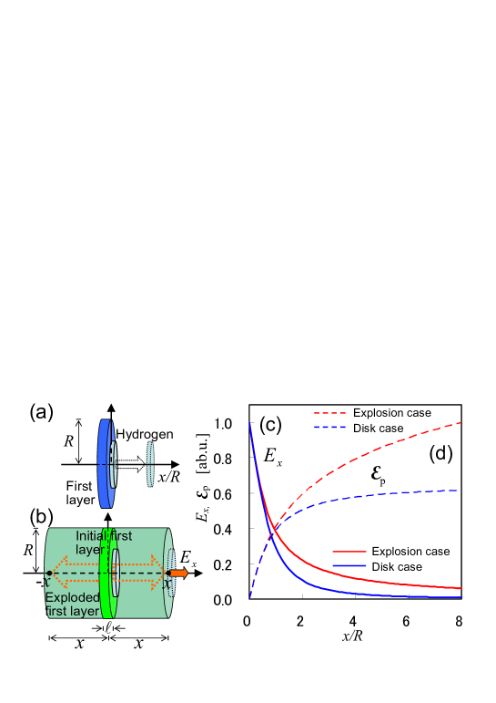
In the model described above, the protons are accelerated in the electric field given by Eq. (1). This electric field decreases rapidly with the distance from the disk surface as shown in Fig. 1(c) (blue solid line). To enhance the ion acceleration, we must produce the condition where the ions are being accelerated for a longer time by the electric field which more slowly decreases with distance as seen by the protons. This can be achieved using a moving electrostatic potential, associated with the motion of the first layer of the double-layer target. With a sufficiently high power laser the first layer can be pushed forward in the RPDA regime ESI1 ; SSB . However, as suggested in SSB , a Coulomb explosion of the first layer can produce a moving electrostatic potential, by which the second layer is accelerated.
Here we estimate the effect of this Coulomb explosion of the first layer. To simplify the discussion, we assumed that the disk target expands in the shape of cylinder. It is assumed that the target thickness, , of the initial shape expanded to and and the target radius, , expanded to , where , and the distance of a proton from the expanding target surface is . The electric field at the proton position is
| (4) |
where is the value for the initial disk. When the is a linear function of of the form , is a real number and , and the proton is on the expanding target surface, this electric field is . Here and increase with the decrease of . In the limit of , (Fig. 1(b)), this electric field is . This electric field is shown in Fig. 1(c) (red solid line). The electric field of this case is higher than the disk case at all positions. The energy gain of protons is . The proton energy of the Coulomb explosion case is 1.6 times higher than the disk case until the position =8 (see Fig. 1(d)). In a spherical expansion, on the other hand, the proton energy is the same in the expanding target and non-expanding one.
The acceleration rate is higher when the front of the expanded first layer has the velocity close to the accelerating protons. That is, we should make a strong Coulomb explosion of the first layer. The higher the of the ions, the greater their energy. A stronger Coulomb explosion occurs in the high material. Therefore, we can obtain higher energy protons by using the high material in the first layer. This consideration is corroborated by the simulations described below.
The simulations were performed with a 3D massively parallel electromagnetic code, based on the PIC method CBL . The dimensional quantities are given in terms of the laser wavelength m; the spatial coordinates are normalized by and the time is measured in terms of the laser period, . We use an idealized model, in which a Gaussian -polarized laser pulse is incident on a double-layer target. The laser pulse with the dimensionless amplitude , which corresponds to the laser peak intensity of W/cm2, is long in the propagation direction and is focused to a spot with size (FWHM), which corresponds to the laser power of TW and laser energy of J. Both layers of the double-layer target are shaped as disk. The first layer has the diameter of and thickness of . The second, hydrogen, layer is narrower and thinner; its diameter is and thickness is . Although, the first layer material is varied, it is assumed that it is comprised of ions with the charge state of and the number of ions is the same in all cases. The electron density inside the first layer is cm-3 and inside the hydrogen layer is cm-3. The total number of quasi-particles is .
The laser pulse is normally or obliquely incident on the target. The oblique incidence of the laser pulse is realized by rotating the target about the axis. In the normally incident cases, the number of grid cells is equal to along the , , and axes. Correspondingly, the simulation box size is . In the obliquely incident cases, the dimension of is set to be two times larger than the normally incident cases MEBKY2 . The boundary conditions for the particles and for the fields are periodic in the transverse (,) directions and absorbing at the boundaries of the computation box along the axis. In figures 2,3,5, the axis denotes the direction perpendicular to the target surface and the axis is parallel to the target surface, while the direction of axis is the same as the direction of the axis. The origin in the coordinates is located at the center of the rear surface of the initial first layer.
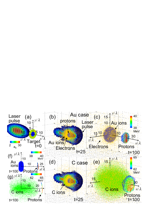
We show two results, one is a case using gold for the first layer and the other case uses carbon. In order to examine the dependence of the proton energy versus the first layer material, we performed simulations with the normal incidence of laser pulse. Figures 2(b),(c) show the case of gold for the first layer and Figs. 2(d),(e) show the case of carbon. We see that the carbon ions are distributed over a wider area than in the gold case by the Coulomb explosion. Figures 2(f),(g) show a 2D projection onto the plane. Here we present the region of to see the ion density around the plane.
In the carbon case, the center of the exploded first layer moves in the laser propagation direction (Fig. 2(g)). This velocity is about of that of the protons. We show the estimation of this moving first layer effect on the proton energy. We assume that the first layer velocity is and the second layer ion, proton, velocity is . That is, the accelerating electric field moves at speed , it is denoted . For , we obtain the proton energy
| (5) |
where is the proton energy in the case of a non-moving first layer, and is the proton mass. For the proton velocity in the non-moving first layer we obtain . in our simulation, , so we obtain higher energy protons by this moving first layer.
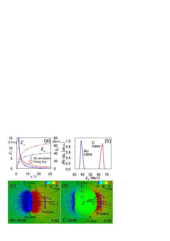
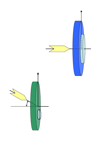
Figure 3(a) shows the simulation results of the accelerating electric field that the protons see in the gold and carbon case, and the energy gain of the protons in each case. The accelerating electric field of the carbon case is higher than the gold case and the energy gain of the protons in the carbon case is higher too. It is similar to the theoretical lines (Fig. 1(c)(d)). Figure 3(b) shows the energy spectrum of the generated protons for the gold case and the carbon case. The average proton energy, , is 38MeV in the gold case and 63MeV in the carbon case. The proton energy in the carbon case is 1.7 times higher than the carbon case. The proton energy spreads are 8.3 in the gold case and 5.6 in the carbon case. Figures 3(c),(d) show the particle distribution and the component of the electric field, , which accelerates the protons, around the target at 50. The black solid lines show the on the axis. The value of in the carbon case at the proton’s position is TV/m and the gold case is TV/m. That is, the protons in the carbon case undergo a stronger acceleration.
Figure 4 shows the average proton energy for some different materials of the first layer. The horizontal axis is for , where is the charge state of the ion and is the atomic mass number. The vertical axis is for the proton energy which is normalized by the energy in the gold case. The higher energy protons can be obtained by using a larger ratio of . That is, higher energy protons are obtained by using a high material in the first layer of a double-layer target.
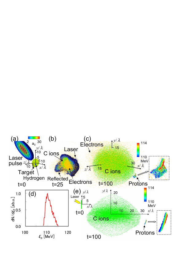
In Fig. 5 we show the case of an oblique incidence of the laser pulse onto the carbon target, showing the highest rate of proton acceleration in the above consideration. The laser pulse incidence angle is MEBKY . The small hydrogen layer with the diameter of is shifted below the target center MEBKY2 (see Fig.5(a)). The other parameters are the same as described above. Figures 5(b),(c) show the electric field magnitude and distribution of ions. Half of the box is removed to reveal the internal structure of the electric field. We see that the carbon ions are distributed over a wider area due to the Coulomb explosion. Figure 5(d) shows the energy spectrum of the generated protons at . We obtain protons with an average energy, , of MeV, an energy spread, , of 2.8, and the number of generated protons of . Figure 5(e) is the 2D projection onto the plane.
In conclusion, proton acceleration driven by a laser pulse irradiating a double-layer target, consisting of some high- atom layer and a hydrogen layer, is investigated with the help of 3D PIC simulations. We find that higher energy protons are obtained by using a material with a high charge-to-mass ratio in the first layer of a double-layer target. As seen in our simulations, due to the strong Coulomb explosion occurring in such a material, the protons keep accelerating for a longer time. We show that three times higher energy protons are obtained, even using the same laser pulse, by using the optimum material for the first layer and selecting the optimum incidence angle of the laser pulse.
The computation as performed using the PRIMERGY BX900 supercomputer at JAEA Tokai.
References
- (1) S. V. Bulanov and V. S. Khoroshkov, Plasma Phys. Rep. 28, 453 (2002); S. V. Bulanov, et al., Phys. Lett. A 299, 240 (2002); C. Ma, et al., Med. Phys. 34, 2550 (2007).
- (2) M. Roth, et al., Phys. Rev. Lett. 86, 436 (2001); V. Yu. Bychenkov, et al., Plasma Phys. Rep. 27, 1017 (2001); S. Atzeni, et al., Nucl. Fusion 42, L1 (2002).
- (3) I. Spencer, et al., Nucl. Instrum. Methods Phys. Res. B 183, 449 (2001); S. Fritzler, et al., Appl. Phys. Lett. 83, 3039 (2003).
- (4) K. W. D. Ledingham, et al., J. Phys. D 36, L79 (2003).
- (5) M. Borghesi, et al., Phys. Plasmas 9, 2214 (2002).
- (6) T. Esirkepov, et al., Phys. Rev. Lett. 92, 175003 (2004); S. V. Bulanov et al., Phys. Rev. Lett. 104, 135003 (2010).
- (7) S. V. Bulanov, et al., Nucl. Instrum. Methods Phys. Res. A 540, 25 (2005).
- (8) M. Borghesi, et al., Phys. Rev. Lett. 92, 055003 (2004).
- (9) S. S. Bulanov et al., Phys. Rev. E 78, 026412 (2008); S. S. Bulanov et al., Med. Phys. E 35, 1770 (2008).
- (10) T. Yu, et al., Phys. Rev. Lett. 105, 065002 (2010).
- (11) H. B. Zhuo, et al., Phys. Rev. Lett. 105, 065003 (2010).
- (12) T. Esirkepov, et al., Phys. Rev. Lett. 89, 175003 (2002); C. Schwoerer, et al., Nature 439, 445 (2006).
- (13) R. A. Snavely, et al., Phys. Rev. Lett. 85, 2945 (2000).
- (14) E. L. Clark, et al., Phys. Rev. Lett. 84, 6703 (2000).
- (15) C. K. Birdsall and A. B. Langdon, Plasma Physics Via Computer Simulation, McGraw-Hill, New York (1985).
- (16) T. Morita, et al., Phys. Plasmas 16, 033111 (2009).
- (17) T. Morita, et al., Phys. Rev. Lett. 100, 145001 (2008); T. Morita, et al., Plasma Phys. Control. Fusion 51 (2009).