Quantum Corrals and Quantum Mirages on the Surface of a Topological Insulator
Abstract
We study quantum corrals on the surface of a topological insulator (TI). Different resonance states induced by nonmagnetic (NM), antiferromagnetic (AFM), and ferromagnetic (FM) corrals are found. Intriguingly, the spin is clearly energy-resolved in a FM corral, which can be effectively used to operate surface carrier spins of TI. We also show that an observable quantum mirage of a magnetic impurity can be projected from the occupied into the empty focus of a FM elliptic corral, while in NM and AFM corrals the mirage signal becomes negligibly weak. In addition, the modulation of the interaction between two magnetic impurities in the quantum corrals is demonstrated. These prominent effects may be measured by spin-polarized STM experiments.
pacs:
73.20.-r, 72.10.Fk, 75.30.HxI Introduction
Spintronics and quantum information are active areas in the modern condensed matter physics. Spin-orbit interaction (SOI) has opened a door for controlling electron spins in materials, and some semiconducting spintronics devices based on the SOI have been proposed in last decade Baibich . Very recently, a new quantum matter phase, named as topological insulator (TI) suggested by a series of theoretical Kane ; Bernevig ; Fu ; Moore ; Qi ; Zhanghj reports, has been detected experimentally in two-dimensional HgTe quantum well Konig and three-dimensional Bi2Se3-family materials Hsieh1 ; Chen ; Xia characterized by the inherent strong SOI. One significant issue in such systems is that the strong SOI-induced Berry phase (chiral spin texture) Hsieh2 ; Roushan suppresses backscattering, such that the topological surface states exhibit quantum-entanglement effects Fu ; Konig ; Hsieh1 and could be useful for performing fault-tolerant quantum computation Zhang ; Fu1 ; Moore1 .
In addition, some nanoscale atomic structures, in which the electrons are confined, have potential applications in spintronics and quantum computations. For example, quantum corrals, which is a closed geometrical array constructed by impurities on tow-dimensional (2D) surface of materials, is a candidate for applications in quantum information Kane1 ; Morr . Especially, when a manipulated magnetic atom is located at one focus of the elliptic corral, one can detect the signature not only at this focus but also at the empty one, which is named as quantum mirage effect. Therefore, the quasiparticle interference state around impurities is an important candidate for these potential applications of TI materials. The advanced progress of scanning tunneling microscopy (STM) has made it possible to probe impurity sates for various materials, and many efforts have been devoted to this active field. Over the past few years, quantum corrals on surfaces of noble metals Heller ; Manoharan ; Aligia ; Hallberg ; Moon ; Rossi ; Fransson ; Barr ; Walls and superconductors Morr have been extensively studied for exploring the surface electron interference effects. Lots of intriguing quantum phenomena have been found, including quantum mirages Morr ; Manoharan ; Hallberg ; Aligia ; Moon , Kondo effect Rossi , quantum invisibility Fransson , electron lifetime and resonance widths Barr , SOI effect in quantum corrals Walls and so on. Inspired by these interesting observations in corrals and the potential applications to quantum computations of TI, in this paper we study the quantum corrals, quantum mirages, and interactions between two magnetic impurities located in corrals on the TI surface. Intriguingly, some unique phenomena are observed, which dramatically distinguish the present corral-TI system from previously reported ones harnessed on the ordinary metals or semiconductor heterostructures. We show that an energy gap is opened in the ferromagnetic (FM) corral, while it is not found in antiferromagnetic (AFM) and nonmagnetic (NM) cases. Remarkably, the spin can be energy-resolvable (-unresolvable), and the quantum mirage is clear (unclear) in FM (AFM) corrals. In addition, the role of NM and FM corrals in modulating the interaction between two magnetic impurities is more prominent than AFM ones. Our predictions, which can be measured using spin-polarized STM Meier , provide to reveal peculiar topological quantum interference properties of TI surface states, based on which new applications for spintronics and quantum computations with TI systems may be proposed.
II Model and method
We model the TI surface, on which adatoms are adsorbed to construct a quantum corral, by a low-energy effective massless Dirac Hamiltonian written as
| (1) |
where is the Fermi velocity, is the planar momentum, are the Pauli spin matrices, and is the total number of impurities. We take Fermi velocity , and use lattice constant as the distance unity and as the energy unity.
| (2) |
is the potential of the impurity located at site , with () the potential (magnetic) scattering strength, and the spin of a magnetic impurity. We define () for scalar impurities, while () for magnetic ones in all calculations. If the measurements are performed at a temperature higher than the Kondo temperature, which is K in the magnetic doped Bi2Se3 nanoribbons Cui , the coupling will not exceed the critical value before a Kondo effect occurs. For magnetic corrals, in this paper we assume that the distance between impurities is large enough and the exchange coupling , so that the Ruderman-Kittel-Kasuya-Yosida interactions between impurity spins and Kondo screening of the spin by the band electrons are neglected, and the impurity spin acts as a classical local magnetic moment under mean-field approximation Morr ; Liu ; Biswas ; Balatsky .
The quantum interference effects that we discuss can be observed in measurements of the TI surface electron local density of states (LDOS) , which can be calculated by
| (3) |
The electron Green’s function is expressed as
| (4) |
where the matrix is
| (5) |
where the unperturbed Green’s function can be obtained by the Fourier transformation of the Green’s function
| (6) |
For numerical calculations, the total Green’s function in Eq. (4) can be rewritten as
| (7) |
where
| (9) | ||||
| (14) |
which denote the propagation of electrons from the STM tip to the impurities as well as from the impurities to the STM tip. The matrix in Eq. (6) is a rewritten form of the Eq. (5) for the matrix, which is given by
| (15) |
with the impurity Hamiltonian
| (16) |
containing all of the impurity scattering potentials (). The information about the propagation between the impurities are included in , which can be expressed as
| (17) |
As a result, one can obtain
| (18) |
where is a unity matrix. Finally, by using the Eqs. (6-12), one can easily finish the numerical calculations, and then get the LDOS.
III Results and discussions
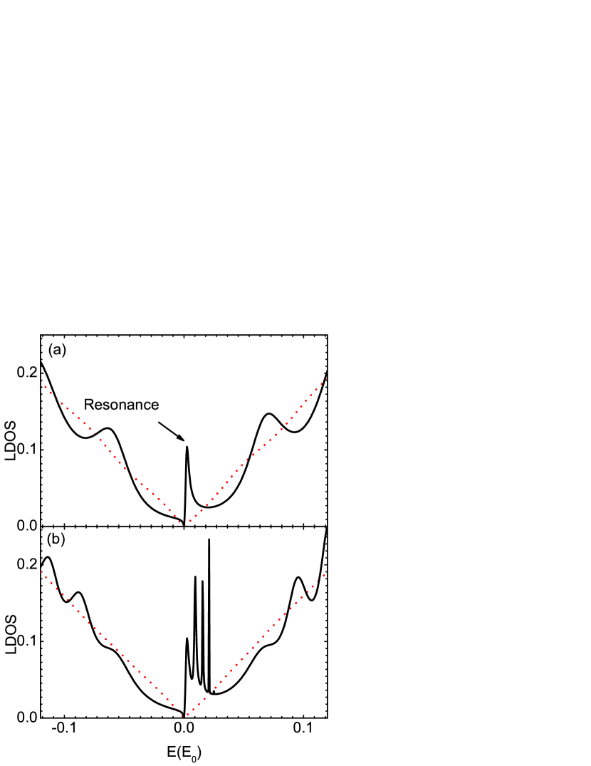
We first study a circular quantum corral of radius comprising NM adatoms on TI surface. Comparing to the case of clean surface, we find that the local correction of LDOS by the NM corral is weak when the potential is not strong enough (such as ), as indicated by the red dashed curves in Fig. 1. With increasing the potential strength, however, there turns to occur an impurity resonance peak projected at the Dirac point, as shown by the black curves in Fig. 1, corresponding to a sufficiently strong potential (). Furthermore, due to the quantum confinement and interference induced by multiple scattering, additional peaks at other band regions are found (see the black curve in Fig. 1(b) for site ). This prominently differs from the case of a single NM impurity Biswas on the TI surface. The NM resonant state at the Dirac point is doubly degenerate according to the Kramers’ theorem Balatsky , and these peaks will be located at the negative side for a negative potential . Clearly, although the resonance states appear in low-energy regime, signatures of fundamental destruction of the Dirac point due to the NM corral, such as an energy gap opening, does not occur.
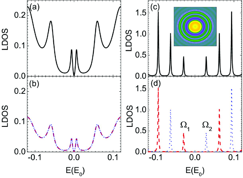
The time-reversal symmetry will be broken by magnetic impurities (we assume the impurity spins to be polarized along the -axis), therefore, the LDOS changes considerably when the quantum corrals are constructed by magnetic impurities. For this straightforward reason, we analyze the following two cases: (i) an AFM aligned corral with a zero total spin and (ii) a FM aligned corral. Theoretical simulations of LDOS in the presence of an AFM circular corral on TI surface are plotted in Fig. 2(a) and 2(b). It is clear that due to the breaking of the time-reversal symmetry, differing from the NM case, the resonance in the center of magnetic corrals splits into spin-polarized peaks symmetrically located about both sides of the Dirac cone. In fact, when the STM tip is moved from the center of corrals (i.e., ), these resonance states will split even more, which is not shown here for briefness. It is found that by tuning the impurity potential up to the resonant states are not clear in the AFM corral, therefore, is representatively chosen in Fig. 2(a) and 2(b). In the AFM case, at least two facts should also be noticed. For one thing, no gap-opening at the Dirac point is found because the total spin is zero in an AFM corral. For another, the density of spin-up and spin-down states,
| (19) |
are energy-unresolvable in AFM circular corral, as shown in Fig. 2(b).
Through comparison of the numerical results between AFM and NM corrals, we can conclude that the role of magnetic impurities in reshaping low-energy LDOS should be more subtle than NM scattering potentials on TI surfaces, which is consistent with the results in previous single-impurity studies (e.g. Refs. Liu ; Biswas ). This argument is more remarkable in FM corrals, in which the resonance states are easily obtained even with a weaker scattering potential. This can be seen clearly in Fig. 2(c) and 2(d), where the scattering strength is chosen as . The quantum interference becomes so strong that not only the resonance peaks become sharper, but also the LDOS is suppressed, and especially a gap is opened over the Dirac point. This prominent phenomenon was not observed in both NM and AFM corrals. Surprisingly, observing the Fig. 2(d) where the blue dotted curve is for while red dashed one represents , we can find that the spin is energy-resolved in FM corrals. For example, consider the pair of resonance peaks marked in Fig. 2(d). In this case, () mainly arises from impurity scattering with spin-down (-up) electrons, which could be measured in the spin-polarized STM experiments. These pure spin-resolved states allows us to operate the spin-up or -down electrons selectively, thus this is an excellent candidate for applications in spin switch and magnetic storage element in nanometer scale. A typical spatial oscillation pattern of the LDOS for a FM corral with energy close to the experimentally accessible Fermi energy is shown in the inset of Fig. 2(c).
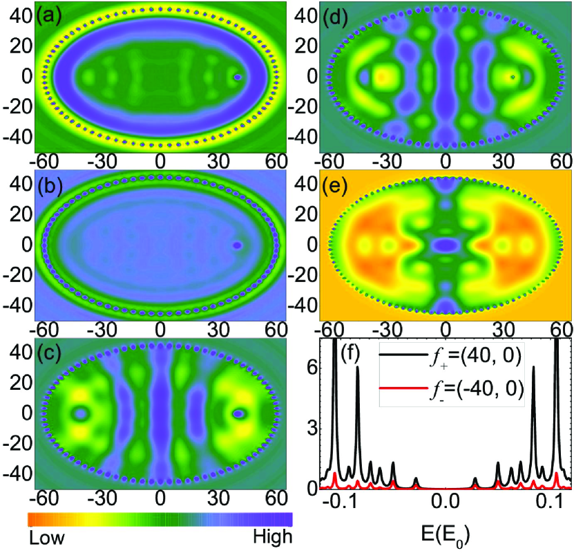
We turn now to focus on the quantum mirage effect of the elliptical corrals on TI surface. In Fig. 3 we present the quantum mirages in NM [Fig. 3(a)], AFM [Fig. 3(b)], and FM [Fig. 3(c)-(f)] corrals with impurities, , , eccentricity and foci . Usually, a good mirage effect is projected in certain ellipses that have large peak amplitudes at the foci Fiete . However, we find that by tuning the impurity potential up to (or ) the resonant states are not clear in either NM or AFM corrals, and thereby the quantum mirages in LDOS at empty focus projected by a magnetic impurity located at focus are too weak to be observed as seen in Figs. 3(a) and 3(b). Things will be absolutely different in a FM corral since the LDOS is suppressed and resonant states could be easily obtained. As expected, a quantum mirage at the empty focus, in a FM corral can be clearly observed [as seen in the spatial pattern in the LDOS shown in Fig. 3(c)]. Corresponding to Fig. 3(c), we show the spectral property of mirage versus the energy in Fig. 3(f), where the positions of resonance peaks of the mirage at the empty focus (red curve) are in good agreement with those at the occupied focus (black curve). Consequently, the FM quantum corrals rather than NM and AFM ones can provide a good nanoscale facility to project quantum mirages on the TI surface. The LDOS pattern will change when the magnetic impurity is moved off the focus, similar to other systems Morr , since different locations of the impurity give rise to different excited eigenmodes in corrals. For example, when the impurity is moved to , a much weaker quantum mirage is projected at , as illustrated in Fig. 3(d), and the spatial oscillations in LDOS changes completely when the impurity is placed at the center [] as shown in Fig. 3(e). Besides, the LDOS in the corrals with oscillating potentials will exhibit some new features, and the quantum mirage will be destroyed (not shown here). The quantum mirages in elliptical FM corral on TI surface can be used to transmit information without wires, which offers a simple technique for manipulating the coherent quantum-state in real-space Moon , and may open a new door for the technological realization of quantum computers of low energy consumption by using TI materials.
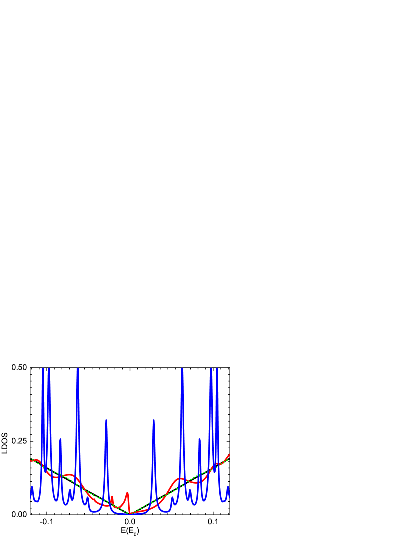
The interference between two magnetic impurities is another interesting and important issue, which is dependent on many physical factors including spatial locations, impurity scattering strength, relative angle between two impurities spins, and so on. We briefly discuss the influence of quantum corrals on the quantum interference effects between two spin-parallel magnetic impurities apart on the TI surface. Taking into account these two magnetic impurities, and using the same corral setup as in Fig. 3, the calculated LDOS at the center are shown in Fig. 4. From Fig. 4 one can find three prominent features as follows: (i) the NM corral will induce an obvious bound state peak (red curve) at the Dirac point; (ii) the AFM corral has little influence (green dotted curve); (iii) the FM corral enhances the interaction between the two magnetic impurities (blue curve) along with a number of resonance peaks and an opened energy gap across the Dirac point. Therefore, we can conclude that both NM and FM corrals (rather than AFM ones) on the TI surface may be used to manipulate the interaction between magnetic impurities. This is different from that in superconductors Morr in which the quasiparticle resonance is sensitive to the AFM corral.
Recently, some STM experiments about the impurity and defects on Bi1-xSbx Roushan , Bi2Te3 Alpichshev ; XueQK , and Bi2Se3 Alpichshev2 have been performed and resonance states at Dirac point have been observed in Bi2Se3 Alpichshev2 , where the scattering potential strength is consistent with the parameters used herein. To experimentally verify our predictions, the spin-polarized STM tip and strong scattering potentials are required, which we believe are achievable in current experimental capabilities, thereby, we hope our findings could be observed in future experiments.
Compared to an ordinary (e.g. narrow gap) insulator or metal, the consequence of the TI that we show in this paper is its unique quasiparticle interference states confined in a corral. For example, as shown in Figs. 2(c) and 2(d), the quasiparticle resonance states in a FM corral is highly spin resolved in energy, which fundamentally distinguish the present corral-TI system from previously reported ones harnessed on the ordinary metals or semiconductor heterostructures. These novel phenomena are closely associated with the topological chiral spin structure for TI surface states of Dirac type, and are totally absent in an ordinary insulator or metal, in which the quasiparticle interference states in a quantum corral have been extensively studied. Different from the normal metal surface states, the Dirac point in TI surface states is so stable against impurity scattering that the weak potential impurities cannot induce significant modification in LDOS near the Dirac point, such as resonance states at Dirac point. Whereas, the low-energy resonance states due to the impurity scattering on ordinary insulator or metal surface are easily to be observed with weaker potential impurity Lobos . Moreover, even if the Rashba SOI in metal surface states is taken into account, the main features of quantum corrals on normal metal Au(111) surface is similar to those without SOI since the Rashba SOI is much weaker than the kinetic energy term in ordinary insulator or metal.
Besides, due to the single Dirac point nature, no complicated intervalley scattering events occur on TI surface. Therefore, it can be expected that in situ measurement or even manipulation of impurity scattering processes on TI surfaces should pave a promising way to study electronic structures and find extraordinary quantum phenomena in various TI materials. The effects observed above, especially induced by FM corral, may provide a useful method to control the electron’s spin, and provides a useful criterion to distinguish the aligned mode of the magnetic corral on TI surface from other 2D systems with an even number of Dirac points, such as graphene. In graphene, the two components of the low-energy Hamiltonian indicate the pseudospin of the two sublattices not real spin that link to the quasiparticle momentum, while the twofold spin degeneracy is preserved, and the spin does not couple to magnetic impurities directly in graphene. Consequently, no net spin-polarized LDOS or chirality will be observed in graphene even if the intervalley scattering is ignored.
IV Conclusions
In summary, we have studied electron interference in the LDOS induced by NM, AFM, and FM quantum corrals on a TI surface. We have found that the impurity resonance states are much easier to occur in a FM corral, in which the resonant peaks become much sharper with increasing the magnetic impurity potentials, so that the LDOS is suppressed and an energy gap at the Dirac point is opened. Especially, the spin-up and spin-down LDOSs are well energy-resolved in a FM corral, which may be useful for spin selection and developing spintronics devices in TI. Furthermore, a quantum mirage of a magnetic impurity bound state is projected in a FM elliptic corral, while for the NM or AFM corrals it is too weak to be observed. In addition, we have also discussed the interaction between two magnetic impurities in quantum corrals. Interestingly, this interaction is prominently enhanced in NM and FM corrals, rather than in an AFM one. These effects may offer new guide in manipulating topological surface states, as well as potential applications for spintronics and quantum information.
The authors would like to thank Jamie D. Walls for helpful suggestions on the manuscript. This work was supported by NSFC under Grants No. 90921003, No. 60776063, No. 60821061, and 60776061, and by the National Basic Research Program of China (973 Program) under Grants No. 2009CB929103 and No. G2009CB929300.
References
- (1) S. Datta and B. Das, Appl. Phys. Lett. 56, 695 (1990).
- (2) C. L. Kane and E. J. Mele, Phys. Rev. Lett. 95, 146802 (2005).
- (3) B. A. Bernevig, T. L. Hughes, and S.-C. Zhang, Science 314, 1757 (2006).
- (4) L. Fu, C. L. Kane, and E. J. Mele, Phys. Rev. Lett 98, 106803 (2007).
- (5) J. E. Moore and L. Balents, Phys. Rev. B 75, 121306(R) (2007).
- (6) X.-L. Qi, T. L. Hughes, and S.-C. Zhang, Phys. Rev. B 78, 195424 (2008).
- (7) H. Zhang, C.-X. Liu, X.-L. Qi, X. Dai, Z. Fang, and S.-C. Zhang, Nat. Phys. 5, 438 (2009).
- (8) M. König, S. Wiedmann, C. Brüne, A. Roth, H. Buhmann, L. W. Molenkamp, X.-L. Qi, S.-C. Zhang, Science 318, 766 (2007).
- (9) D. Hsieh, D. Qian, L. Wray, Y. Xia, Y. S. Hor, R. J. Cava, M. Z. Hasan, Nature 452, 970 (2008); D. Hsieh,Y. Xia, D. Qian, L. Wray, F. Meier, J. H. Dil, J. Osterwalder, L. Patthey, A.V. Fedorov, H. Lin, A. Bansil, D. Grauer, Y. S. Hor, R. J. Cava, and M. Z. Hasan, Phys. Rev. Lett. 103, 146401 (2009).
- (10) Y. L. Chen, J. G. Analytis, J.-H. Chu, Z. K. Liu, S.-K. Mo, X. L. Qi, H. J. Zhang, D. H. Lu, X. Dai, Z. Fang, I. R. Fisher, Z. Hussain, Z.-X. Shen, Science 325, 178 (2009).
- (11) Y. Xia, D. Qian, D. Hsieh, L.Wray, A. Pal, H. Lin, A. Bansil, D. Grauer, Y. S. Hor, R. J. Cava, and M. Z. Hasan, Nat. Phys. 5, 398 (2009).
- (12) D. Hsieh, Y. Xia, L. Wray, D. Qian, A. Pal, J. H. Dil, J. Osterwalder, F. Meier, G. Bihlmayer, C. L. Kane, Y. S. Hor, R. J. Cava, M. Z. Hasan, Science 323, 919 (2009).
- (13) P. Roushan, J. Seo, C. V. Parker, Y. S. Hor, D. Hsieh, D. Qian, A. Richardella, M. Z. Hasan, R. J. Cava, and Ali Yazdani, Nature 460, 1106 (2009).
- (14) S.-C. Zhang, Physics, 1, 6 (2008).
- (15) L. Fu and C. L. Kane, Phys. Rev. Lett. 100, 096407 (2008).
- (16) J. E. Moore, Nat. Phys. 5, 378-380 (2009).
- (17) B. E. Kane, Nature, 393, 133, (1998).
- (18) D. K. Morr and N. A. Stavropoulos, Phys. Rev. Lett. 92, 107006 (2004); N. A. Stavropoulos and D. K. Morr, Phys. Rev. B 71, 140501(R) (2005).
- (19) E. J. Heller, M. F. Crommie, C. P. Lutz, and D. Eigler, Nature 369, 464 (1994).
- (20) H. C. Manoharan, C. P. Lutz, and D. M. Eigler, Nature 403, 512 (2000).
- (21) A. A. Aligia, Phys. Rev. B 64, 121102(R) (2001).
- (22) K. Hallberg, A. A. Correa, and C. A. Balseiro, Phys. Rev. Lett. 88, 066802 (2002).
- (23) C. R. Moon, C. P. Lutz, and H. C. Manoharan, Nat. Phys. 4, 454 (2008).
- (24) E. Rossi and D. K. Morr, Phys. Rev. Lett. 97, 236602 (2006).
- (25) J, Fransson, H. C. Manoharan, and A. V. Balatsky, Nano Lett. 10, 1600 (2010).
- (26) M. C. Barr, M. P. Zaletel, and E. J. Heller, Nano lett. 10, 3253 (2010).
- (27) J. D. Walls and E. J. Heller, Nano Lett. 7, 3377 (2007).
- (28) F. Meier, L. Zhou, J. Wiebe and R. Wiesendanger, Science 320, 82 (2008).
- (29) J. J. Cha, J. R. Williams, D. Kong, S. Meister, H. Peng, A. J. Bestwick, P. Gallagher, D. Goldhaber-Gordon, and Y. Cui, Nano Lett. 10, 1076, (2010).
- (30) Q. Liu, C.-X. Liu, C. Xu, X.-L. Qi, and S.-C. Zhang, Phys. Rev. Lett. 102, 156603 (2009).
- (31) R. R. Biswas and A. V. Balatsky, Phys. Rev. B 81, 233405 (2010).
- (32) A. V. Balatsky, I. Vekhter, and J.-X. Zhu, Rev. Mod. Phys. 78, 373 (2006).
- (33) G. A. Fiete and E. J. Heller, Rev. Mod. Phys. 75, 933 (2003).
- (34) Z. Alpichshev, J. G. Analytis, J.-H. Chu, I. R. Fisher, Y. L. Chen, Z. X. Shen, A. Fang, and A. Kapitulnik, Phys. Rev. Lett. 104, 016401 (2010).
- (35) T. Zhang, et al., Phys. Rev. Lett. 103, 266803 (2009).
- (36) Z. Alpichshev, R. R. Biswas, A. V. Balatsky, J. G. Analytis, J.-H. Chu, I. R. Fisher, and A. Kapitulnik, arXiv:1108.0022v1 (2011).
- (37) A. Lobos and A. A. Aligia, Phys. Rev. B 68, 035411 (2003).