Edge States and Stacking Effects in Nanographene Systems
Abstract
Bilayer graphene nanoribbon with zigzag edge is investigated with the tight binding model. Two stacking structures, and , are considered. The band splitting is seen in the structure, while the splitting in the wave number direction is found in the structure. The local density of states in the structure tend to avoid sites where inter-layer hopping interactions are present.
I Introduction
The graphite, multi-layer, and single-layer graphene materials have been studied intensively, since the electric field effect has been found in atomically thin graphene films.novo These materials can be regarded as bulk systems. On the other hand, nanographenes with controlled edge structures have been predicted to have localized states along the zigzag edges.fujita The presence of the edge states has been observed by experiments of scanning tunneling spectroscopy.kobaya ; niimi Thus, the studies of the edge states are one of the interesting topic of the field. The recent atomic bottom-up fabrication of nanoribbons really promotes experimental and theoretical investigations.cai
Previously, one of the present authors has studied the stacking effects of the nanographene by considering weak inter-layer hopping interactions in the tight binding model.hrgy1 ; hrgy2 The cluster calculations have been performed, and compared with experiments of the magnetic properties. It has been found that open shell nature of the electronic orbital of the each layer is important. The existence of the spin in the each layer gives rise to the magnetism of the stacked nanographene. Therefore, the simple tight binding model is effective.
In this paper, bilayer graphene nanoribbon with zigzag edge is investigated with the tight binding model. Two stacking structures, and , are considered. The band splitting is seen in the structure, while the splitting in the wave number direction is found in the structure. The local density of states in the structure tend to avoid sites where inter-layer hopping interactions are present.
This paper is organized as follows. In the next section, the model is explained. The results are shown in Section 3. The paper is closed with summary in Section 4.
II Model
We consider the following tight binding model
| (1) |
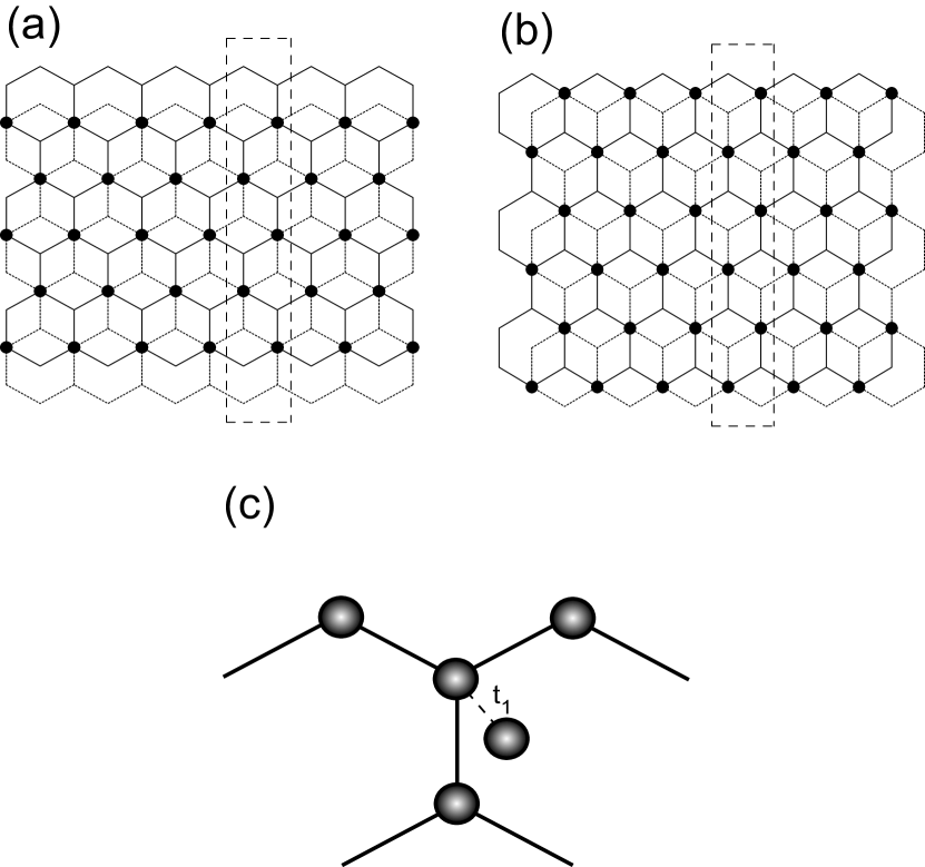
where and are the annihilation operators of electrons at the lattice site of the spin on the upper and lower layers, respectively. The quantity is the hopping integral of electrons between neighboring lattice sites. Two stacking patterns, shown in Figs. 1 (a) and (b), are considered. They are named as and structures, respectively. This convention has been used in the literature.lima There are zigzag lines in upper and lower layers. The detailed view near the edge atom in the structure is displayed in Fig. 1 (c). There is a weak hopping integral along the dashed line.
III Results
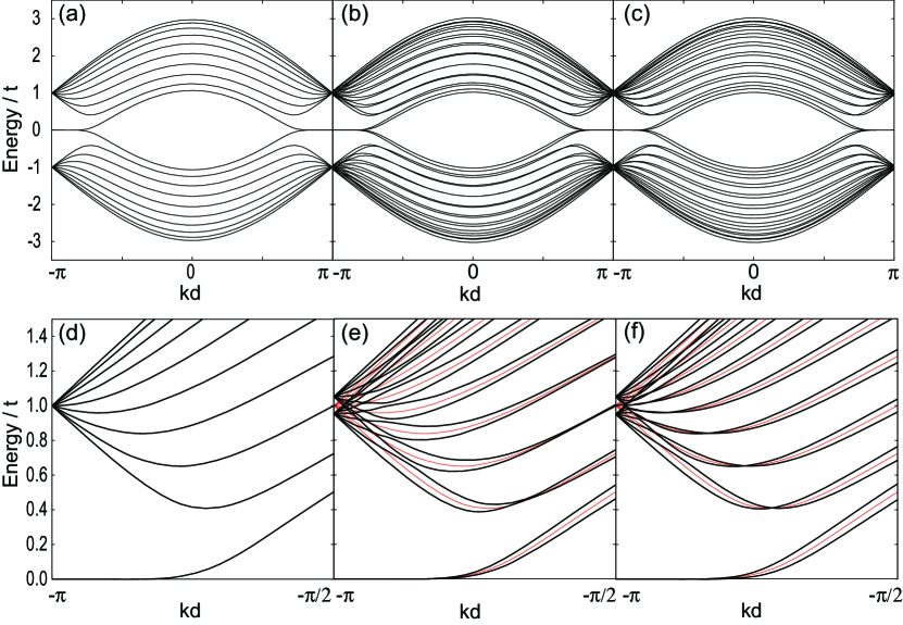
In order to see effects of inter-layer interactions, the tight binding model is solved numerically. The model is solved using the Bloch theory of the band calculation. Energy band structures of the systems are displayed in Fig. 2, for the single layer (a), structure (b), and structure (c). The interlayer interaction strength is . In (b), the split of the energy bands is seen compared with Fig. (a). In contrast, split in the perpendicular direction is small in Fig. (c). In order to see split structures clearly, details near the Brillouin zone edge are magnified for the single layer (d), structure (e), and structure (f). In (e) and (f), the energy bands of the single layer are shown by the red lines for comparison. The nearly flat band due to the edge state in is present at the energy in (d), where is the unit cell length of the one dimensional direction of Figs. 1 (a) and (b). The energy bands starts at at , typical to the graphene structure. In (e), the energy split is magnified again. However, in (f), the energy split is not seen, and split in the wave number direction is found. This property is confirmed by looking at the numerical data, also.
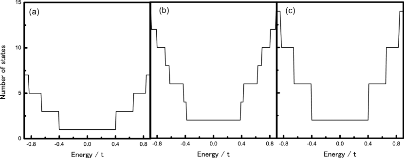
It is interesting to look at how such the difference of the band split in the and structures appear, in the quantization of conductance. Number of states in the energy window for the positive wave number is calculated for the single layer, , and structures. Fig. 3 displays the calculated results for the parameters and again. Around the energy of the single layer (a), the energy band is singly degenerate, as shown in Fig. 2 (d). At the energy , the energy window reaches the first parabolic band, and the number of states jumps by two. The energy window reaches the second parabolic band at the energy . In this way, a series of jumps by two is realized in (a). For the structure (b), number of states near the energy is two due to the bilayer property. There are two steps of the jump of two around the energy , owing to the energy split of the first parabola. Also, two steps are present closely around the energy due to the second parabolic band. On the other hand, each jump of the number of states becomes four for the structure (c) due to the split in the wave number direction. The dependence of the energy reflects the band structures, and this will appear quantization of conductance experimentally.
IV Summary
In summary, weak inter-layer interactions have been considered for the bilayer graphene nanoribbon with zigzag edge. The and stacking structures have been considered. The band splitting is seen in the structure, while the splitting in the wave number direction is found in the structure. The local density of states in the structure tend to avoid sites where inter-layer hopping interactions exist.
References
- (1) K. S. Novoselov, A. K. Geim, S. V. Morozov, D. Jiang, Y. Zhang, S. V. Dubonos, I. V. Grigorieva, and A. A. Firsov, Science 306, 666 (2004).
- (2) M. Fujita, K. Wakabayashi, K. Nakada, and K. Kusakabe, J. Phys. Soc. Jpn. 65, 1920 (1996).
- (3) Y. Kobayashi, K. Fukui, T. Enoki, and K. Kusakabe, Phys. Rev. B 73, 125415 (2006).
- (4) Y. Niimi, T. Matsui, H. Kambara, K. Tagami, M. Tsukada, and H. Fukuyama, Phys. Rev. B 73, 085421 (2006).
- (5) J. Cai et al., Nature 466, 470 (2010).
- (6) K. Harigaya, J. Phys.: Condens. Matter 13, 1925 (2001).
- (7) K. Harigaya, and T. Enoki, Chem. Phys. Lett 351, 128 (2002).
- (8) M. P. Lima, A. J. R. da Silva, and A. Fazzio, Phys. Rev. B 81, 045430 (2010).
- (9) N. M. R. Peres, A. H. Castro Neto, and F. Guinea, Phys. Rev. B 73, 195411 (2006).