An ultra-broadband electromagnetically indefinite medium formed by aligned carbon nanotubes
Abstract
Anisotropic materials with different signs of components of the permittivity tensor are called indefinite materials. Known realizations of indefinite media suffer of high absorption losses. We show that periodic arrays of parallel carbon nanotubes (CNTs) can behave as a low-loss indefinite medium in the infrared range. We show that a finite-thickness slab of CNTs supports the propagation of backward waves with small attenuation in an ultra-broad frequency band. In prospective, CNT arrays can be used for subwavelength focusing and detection, enhancing the radiation efficiency of small sources.
pacs:
78.67.Pt, 61.48.De, 77.84.Lf, 41.20.JbMetal-dielectric nanostructures Ritchie ; Kretschmann have already brought applications to microscopy and sensing Hecht and have the potential for realization of future nanosized optical devices and circuits Engheta . In 2003 the authors of Smith noticed the potential of so-called indefinite metamaterials for subwavelength imaging of objects at electrically large distances from them (the concept of such imaging was first introduced in Pendry ). Indefinite metamaterials are artificial uniaxial materials in which the axial and tangential components of the permittivity and permeability tensors have different signs. In these materials the isofrequency surfaces have hyperbolic shape. This results in a possibility to design a “hyperlens”, where evanescent near fields are transformed into propagating modes and can be transported at electrically long distances Zhang .
The main challenge on the way to realize this and other effects is in the realization of low-loss indefinite materials. For waves of only one linear polarization (TM-polarized waves with respect to the axis of positive permittivity) it is enough to realize a layer of an indefinite dielectric metamaterial Smith3 , whose permeability is unity and only components of the permittivity tensor have different signs. For the visible range such a metamaterial was designed in Smith3 as an array of parallel plasmonic (metal) nanowires. Since all plasmonic phenomena are related to strong dissipation, the axial component of the permittivity has a significant imaginary part which strongly restricts the subwavelength imaging property of the hyperlens Smith3 . In the microwave range, materials with negative permittivity can be realized as arrays of thin metal wires Brown1 ; Brown2 . However, if the field varies along the wires, the properties of the structure are more complicated that those of a continuous medium due to strong spatial dispersion SpatD . The spatial dispersion can be suppressed partially Hudl or even totally Demetr ; Grib ; stas . However, manufacturing of structures Hudl ; Demetr ; Grib ; stas becomes a challenge already at millimeter waves as dimensions need to be quite small for high-frequency applications. For electromagnetic waves in the THz and mid infrared (MIR) range there are no known structures with an indefinite permittivity tensor. The imaginary and real parts of complex permittivity of metals in this range are of the same order and rather high.
Here we show that arrays of metallic carbon nanotubes (CNT) behave as ultra wide-band and low-loss indefinite materials in the THz and MIR ranges. This collective property of arrays results from the quantum properties of individual CNT, namely their high quantum inductance, so-called kinetic inductance Lutt , which leads to suppression of spatial dispersion in arrays of parallel CNTs. This can open a possibility for realization of interesting devices, which we discuss here.
Two-dimensional periodic arrays of carbon nanotubes are fabricated by many research groups. Such CNT arrays form finite-thickness slabs which are used already as field emitters ShFan , biosensors YLin and antennas Wang ; DresselNat . We assume that all nanotubes possess metallic properties that is a realistic assumption in view of recent studies of single-wall CNTs WonBong ; Kusunoki ; modified . Usually carbon nanotubes form hexagonal lattices in arrays in processes of fabrication. However, for low-density arrays for which arrangement of nanotubes is not important. By this reason and for simplicity we assume lattices to be square with the constant .
For eigenwaves propagating in arrays of infinitely long carbon nanotubes we take the space-time dependence of fields and currents as . Effective electromagnetic properties of CNT arrays can be understood from the nonlocal quasistatic model of wire media (WM) stas . In the framework of the effective medium model the CNT array can be considered as a uniaxial material with the permittivity dyadic
| (1) |
where is the permittivity of vacuum (we consider CNTs placed in vacuum). As was shown in stas ,
| (2) |
where is the effective plasma wavenumber , , are the effective inductance and capacitance per unit length, respectively, and the parameter is responsible for losses. Distributed parameters , and for a separate carbon nanotube can be obtained using the model of impedance cylinder and effective boundary conditions developed in Slepyan . According to this model the simple approximate expression for the complex surface conductivity, which is valid for metallic zigzag CNTs at frequencies below optical transitions looks as:
| (3) |
Here is the electron charge, eV is the overlapping integral, is the relaxation time, is the reduced Planck constant. The radius of metallic zigzag CNT, taken as an example, is determined by an integer as , where nm is the interatomic distance in graphene. Since the wall of a single-wall CNT is a monoatomic sheet of carbon, (3) can be considered as the surface conductivity of the carbon nanotube. The surface impedance per unit length
| (4) |
Let us find , and for a separate carbon nanotube. The total inductance per unit length , where is the kinetic inductance Lutt defined by the formula (4), which has a quantum nature, and is the electromagnetic inductance per unit length. For thin CNTs the kinetic inductance strongly dominates over the electromagnetic inductance, e.g., for the zigzag CNT, having the radius nm (), H/m and H/m. This shows that the electromagnetic inductance can be neglected. The total capacitance of CNTs includes the electrostatic capacitance defined as and the quantum capacitance , where is the Fermi velocity which is equal to F/m for graphene and CNT BurkeNT . The two effective capacitances are connected serially. For the considered example F/m, F/m and F/m. Let us estimate the terms entering formula (2) at the frequency THz. One obtains 1/m2, 1/m2 and dimensionless , so the last term in the denominator of formula (2) can be neglected.
Thus strong spatial dispersion is suppressed and the material behaves as a uniaxial free-electron plasma, where electrons can move only along -direction. Apparently, this corresponds to an indefinite medium at frequencies below the plasma frequency, because the permittivity in the directions orthogonal to the tubes is close to unity. Dispersion equation for waves propagating in a uniaxial crystal is Landau
| (5) |
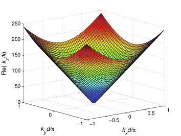
where . Substituting (2) with into Eq. (5) we obtain a simple formula:
| (6) |
which describes a typical conic-type dispersion, see Fig. 1.
Applicability of the described effective medium model was verified comparing with the results of the electrodynamic model, based on Green’s function method IgorPRB . This model takes into account the array periodicity and demonstrates that the effective medium model gives a good agreement with the more accurate theory for small transversal wave numbers ().
In a series of papers published in 2003-2004 by the groups of G. Eleftheriades, C. Caloz and T. Itoh, Pendry’s concept of perfect lens Pendry was experimentally confirmed for a planar analogue of the perfect lens (see also books Elefther and Caloz1 ). Planar networks composed of backward-wave transmission lines (TLN) are surface analogues of bulk double-negative materials. Surface formed by TLN acts as a layer of an indefinite medium, where the spatial dispersion is suppressed Olli . Based on the results of the previous duscussion, we expect that in the THz and MIR ranges a similar backward-wave structure can be realized as an array of aligned CNTs.
Let us consider waves propagating in a finite-thickness slab of CNTs assuming for simplicity that the slab is placed between perfect electric conductor (PEC) and perfect magnetic conductor (PMC) planes, where the PMC boundary models the open-ended interface with free space. The resonant condition for the longitudinal wavenumber reads where is the thickness of the slab. The relation between the transversal wave vector components and the wavenumber in free space is the following:
| (7) |
One can easily show that the derivative if and . Thus, in this regime the finite-thickness slab supports propagation of backward waves, because the group velocity is in the opposite direction to the phase velocity.
This property can be understood also from considering a planar waveguide filled with a CNT array (the array axis is orthogonal to the walls of the waveguide). The propagation constant along the waveguide is equal to
| (8) |
where is a positive integer and is the height of the waveguide SpatD . If , backward-wave propagation is allowed when and forbidden for .
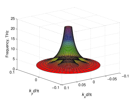
Fig. 2 illustrates dispersion properties of three modes, corresponding to and . There are three embedded conical surfaces. The internal cone corresponds to , and the external one to . One can see that backward waves propagate in the slab in a very wide frequency range. Their properties are quite isotropic in the -plane due to a very small period of the CNT lattice. It follows from formula (8) that there is no low-frequency cutoff for any mode, which can propagate at low frequencies with very large transversal wavenumbers . The effective medium model becomes unapplicable if (compare with results of IgorPRB ).
To suppress the spatial dispersion we do not need any loadings because CNTs possess very high kinetic inductance which ensures that . Comparing to the microwave backward-wave structures based on loaded transmission lines and mushroom layers we note that in CNT arrays there is no parasitic inductance between the cells and parasitic capacitance between the tube ends and the ground plane is very small due to the small cross-section area of the tubes. This leads to a dramatically increased bandwidth of backward-wave propagation and gives the ground to consider CNT arrays as perfect backward-wave metamaterials.
For any optical material at terahertz and infrared ranges one of the most important issues is the level of losses. In CNTs it is determined by the relaxation time at the frequencies below optical transitions. At low frequencies, including values close to a few terahertz, at room temperature usually is estimated as s Slepyan ; Hanson . Such a relaxation time gives the ratio Im/Re at frequencies around 50 THz. However, in other sources this value is taken to be s achiral , which corresponds to considerably higher losses, namely, Im/Re in the same frequency range.
Here we point out one potential application of indefinite dielectric materials based on the conversion of incident evanescent waves into propagating transmitted waves by samples of an indefinite medium. Such a conversion is possible up to very high, in the limiting case infinite spatial frequencies. The idea is illustrated by Fig. 3.
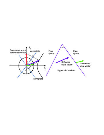
Consider a prism with the wedge angle filled with an indefinite medium with components of the permittivity tensor , . For a wedge made of a CNT array this would correspond to the -oriented tubes. Let an evanescent wave attenuating along and having transversal wave vector component impinges on the left side of the prism. In the isofrequency diagram which is depicted in Fig. 3 (a) the wave vector of the refracted wave selects the point at the medium isofrequency contour so that the component of the refracted wave vector which is parallel to the first asymptote of the hyperbolic isofrequency contour preserves. On the second side of the prism the component of the refracted wave vector which is parallel to the second asymptote of the hyperbola preserves. This holds because both sides are tilted with respect to axis under the same angle as the asymptotes of the hyperbolic isofrequency contour. One can easily derive for this geometry that all incident waves with spatial frequencies transmit into propagating ones () behind its second interface. If , all evanescent waves are transformed into propagating ones. The isofrequency contour with holds for medium of parallel CNT at . The peculiarity of the suggested structure compared to the well known Kretschmann dielectric prism widely used in optics for coupling evanescent optical devices (waveguides and resonators) to free space is the possibility to convert evanescent waves with arbitrary spatial frequencies at a certain frequency. In the Kretschmann method the maximal spatial frequency where the conversion of the evanescent wave into propagating wave (or reverse) is restricted by the permittivity of the material.
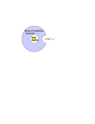
The suggested effect can be practically used for the enhancement of emission from poor emitters, i.e. light sources which low radiation but high level of the electromagnetic energy stored in them. The poor emitter can be placed in a spherical shell of an indefinite material with space-variable optical axis. Namely, the local optical axis is directed radially (it can be implemented as an array of radially oriented CNT). If the shell is spherical, the evanescent waves convert on its internal surface to propagating waves and totally internally reflect on the outer interface. Now we make a cut in the shell as it is shown in Fig. 3 (b). In this part of the shell the inner and outer boundaries of the indefinite medium are strongly not parallel and one can obtain the radiation dramatically enhanced compared to the original radiation of the emitter.
We have shown that arrays of single-wall metallic carbon nanotubes behave as indefinite media. Such properties are provided by a very high kinetic inductance of thin carbon nanotubes. Arrays of finite-length CNTs support propagation of backward waves, which are characterized by low levels of losses in the terahertz and mid-infrared ranges. The finite-thickness carbon nanotube array can be considered as the perfect isotropic backward-wave metamaterial. We have theoretically demonstrated that these materials can be used as transformers of full spectrum of evanescent electromagnetic waves into propagating ones, and as devices for emission enhancement for subwavelength-sized radiators.
This work has been partially funded by the Academy of Finland and Nokia through the Center-of-Excellence program.
References and Notes
- (1) R. H. Ritchie, Phys. Rev. 106, 874 (1957).
- (2) E. Kretschmann, Optics Communications 5, 331 (1972).
- (3) L., Novotny, B. Hecht, Principles of Nanooptics (Cambridge University Press, New York, 2006).
- (4) S. Bozhevolnyi, Plasmonic nanoguides and circuits (Pan Stanford Publishing, Singapore, 2009).
- (5) D. R. Smith, D. Schurig, Phys. Rev. Lett. 90, 077405 (2003).
- (6) J. B. Pendry, Phys. Rev. Lett. 85, 3966 (2000).
- (7) X. Zhang, Z. Liu, Nature Materials 7, 435 (2008).
- (8) Y. Liu, G. Bartal, X. Zhang, Optics Express 16, 15439 (2008).
- (9) J. Brown, Proc. IEE 100, 51 (1953).
- (10) J. Brown, W. Jackson, Proc. IEE 102B, 11 (1955).
- (11) P.A. Belov, R. Marques, S.I. Maslovski, I.S. Nefedov, M. Silveirinha, C.R. Simovski and S.A. Tretyakov, Phys. Rev. B 67, 113103 (2003).
- (12) M. Hudlička, J. Machač, I. Nefedov, Progress In Electromagnetics Research, PIER 65, 233 (2006).
- (13) A. Demetriadou, J. B. Pendry, J. Phys.: Condens. Matter 20, 295222 (2008).
- (14) A. B. Yakovlev et al., M. G. Silveirinha, O. Luukkonen, C. R. Simovski, I. S. Nefedov, S. A. Tretyakov, IEEE Trans. on Microw. Theory and Tech. 57, 2700 (2009).
- (15) S. Maslovski, M. Silveirinha, Phys. Rev. B 80, 245101 (2009).
- (16) P. J. Burke, IEEE Trans. on Nanotechnology 3, 129 (2002).
- (17) S. Fan et al., Science 283, 512 (1999).
- (18) Y. Lin, F. Lu, Y. Tu, Z. Ren, Nano Letters 4, 191 (2004).
- (19) Y. Wang et al., Appl. Phys. Lett. 85, 2607 (2004).
- (20) M. S. Dresselhaus, Nature 432, 959 (2004).
- (21) W. B. Choi et al., Nanotechnology 15, S512 (2004).
- (22) M. Kusunoki et al., Chem. Phys. Lett. 366, 458 (2002).
- (23) A. M. Nemilentsau et al., Phys. Rev. B 82, 235424 (2010).
- (24) G.Y. Slepyan, S. A. Maksimenko, A. Lakhtakia, O. Yevtushenko and A. V. Gusakov, Phys. Rev. B 60, 17136 (1999).
- (25) P.J. Burke, S. Li, and Z. Yu, IEEE Trans. on Nanotechnology 5, 314 (2006).
- (26) L.D. Landau and E.M. Lifshitz, Electrodynamics of Continuous Media (Course of Theoretical Physics, Volume 8) (Butterworth-Heinemann; 2 edition, 1984).
- (27) I. S. Nefedov, Phys. Rev. B 82, 155423 (2010).
- (28) G. V. Eleftheriades, K. G. Balmain, eds. Negative-Refraction Metamaterials: Fundamental Principles and Applications (Hoboken, NJ: J. Wiley and Sons, 2005).
- (29) C. Caloz, T. Itoh, Electromagnetic metamaterials: transmission line theory and microwave applications (New York: J. Wiley and Sons, 2006).
- (30) O. Luukkonen et al., P. Alitalo, F. Costa, C. Simovski, A. Monorchio, S. Tretyakov Appl. Phys. Lett. 96, 081501 (2010).
- (31) G. V. Hanson, IEEE Trans. on Ant. and Prop. 53, 3426 (2005).
- (32) G. Ya. Slepyan, M. V. Shuba, S. A. Maksimenko, and A. Lakhtakia, Phys. Rev. B 73, 195416 (2006).