Approach to accurately measuring the speed of optical precursors
Abstract
Precursors can serve as a bound on the speed of information with dispersive medium. We propose a method to identify the speed of optical wavefronts using polarization-based interference in a solid-state device, which can bound the accuracy of the speed of wavefronts to less than with conventional experimental conditions. Our proposal may have important implications for optical communications and fast information processing.
pacs:
42.50.Gy 42.25.Bs 03.30.+pThe advent of fast information processing in quantum network devices often raises the need for accurate control of light pulse propagation. The speed of the information encoded on the optical pulse should obey the causality Einstein1905 . This seemingly obvious fact has been experimentally proved only recently Gauthier03 . Unlike the well-defined velocity of a point particle, the velocity of a light pulse traveling through an optical material is not precisely defined. The motion of a light pulse can be approximated by the group velocity (), which is given by where is the speed of light in a vacuum, is the refractive index of the material and is the frequency of the light Boyd09 . It can be clearly seen that can be greater than and even be negative when is negative (anomalous dispersion). Experimental studies of fast light propagation include Refs. Wang00 ; Boyd03 ; Gauthier03 ; Dolling06 ; Boyd06 . To resolve the apparent contradictions between fast light propagation and the theory of relativity, optical precursors were introduced by Sommerfeld and Brillouin in 1914 Sommerfeld1914 ; Brillouin1914 ; Brillouin1960 . The theory states that the front edges of an ideal step-modulated pulse propagate at speed because of the finite response time of any physical material and no components can overtake this wave front. The forerunners, now known as Sommerfeld-Brillouin precursors, are followed by the main pulse traveling at its group velocity. This conclusion, while conceptually clear, lacks of experimental evidence directly relating to the speed of optical precursors.
Optical precursors are recently of great interest because they have applications in biomedical imaging Albanese89 , underwater communications Choi04 , and the generation of high peak power optical pulses Jeong10 ; Du10 . A number of theoretical and experimental studies have been carried out Jeong06 ; Aaviksoo91 ; Theory09 ; Falcon03 ; Du08 ; Du09 ; Du11 . Specifically, direct observation of precursors which are separated from the delayed main fields has been achieved with electromagnetically induced transparency (EIT) in cold atoms Du09 ; Du11 . For all these works, the authors claim that the rising edge of the input pulse propagates at the speed of in the form of Sommerfeld precursors. However, considering the rise time of the detecting systems, a time delay of shorter than 1 ps would not be captured if the precursors travel at a speed which differs little from .
In this paper, we propose an experimental method to precisely determine the speed of optical wavefronts propagating through a dispersive medium, i.e., optically pumped Nd3+:YVO4 crystal by interference with a reference pulse traveling through a pure YVO4 crystal. If there is any speed difference between wavefronts in the Nd3+:YVO4 crystal and the YVO4 crystal, the interference pattern will be significantly altered and reveal the influence of Nd3+ ions on the speed of the wavefronts.
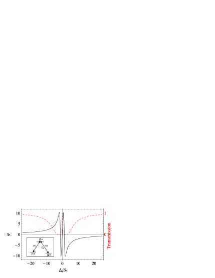
Nd3+:YVO4 crystals (doping level, 10 ppm.) have been systematically investigated as a candidate solid-state quantum memory Gisin08n ; Gisin08 ; Gisin10 . The transition of Nd3+ around 879.705 nm has a narrow homogenous linewidth (63 kHz) and wideband inhomogeneous broadening (2.1 GHz) at low temperature. Nd3+ is a Kramers ion and thus has strong first-order Zeeman effect, which yields a large ground-state splitting under the application of a magnetic field (10-100 GHz/T). From the inset of Fig. 1, it can be seen that a moderate magnetic field splits the ground states into two Zeeman spin levels () which connect to an excited state (). Thus, this provides a -like system Gisin08 ; Gisin10 .
Note that any real pulse has a step-rising front which is composed of the infinite spectral components, even the pure YVO4 crystal cannot response to it, the ideal step-rising wave front propagates at the speed of independent of any medium. While for the light pulse produced by electro-optic modulator (EOM) with a finite rise time, the YVO4 crystal behaves as a wideband response medium, the wave fronts which travels at the speed of are generally too weak for detection in the YVO4 crystal. In both the Nd3+:YVO4 crystal and the pure YVO4 crystal the experimentally detectable wavefront should propagate at the same speed , where is the refractive index for far-detuned frequency components of the input pulse. The refractive index ideally reaches unity and becomes for infinite frequency components. In the Nd3+:YVO4 crystal, the optically pumped Nd3+ ions have a strong dispersion of the narrow-band frequency components that is near the resonance line of the Nd3+. Those components make up the greatly delayed or accelerated main pulse.
The frequency of the probe light is tuned to the Nd3+ absorption line (). It is a square pulse modulated using an EOM with a temporal width of s and a rise (fall) time of s. The input light intensity is assumed to be unity in the following calculations. is the Fourier transform of the input pulse. The Nd3+:YVO4 crystal undergoing EIT is characterized by its linear susceptibility EIT05
| (1) |
where m-1 is the on-resonance absorption coefficient; m-1; is the refractive index of the YVO4 crystal near 879.705 nm for light polarized parallel to the crystal’s symmetric axis index ; is the probe detuning; and is the coupling laser Rabi frequency. 2 is the original absorption bandwidth, which is controlled by the pumping procedure. Here, we choose 1 MHz which is larger than . The dephasing rate between the two ground states is 0.2 kHz. These parameters were chosen based on experimental observations Gisin08 ; Gisin10 . The transmitted field is given by with . Via a fast Fourier transformation (FFT), the transmitted field in time domain can be obtained. There have been some analytical solutions to this problem Theory09 , which fit well with the results obtained using the FFT. However, to preserve the phase of the field for the coming interference experiments, we use FFT to evaluate the integrals. Fig. 1 shows the phase of the photons experiencing with m and the transmitted-field intensity of . It can be seen that far-detuned light experiences a smaller phase shift than near-resonance light. After passing through the EIT medium, the rising and falling edges at and should not experience group delay caused by Nd3+ ions. However, the main fields are approximately delayed by Theory09 ; Du09 .
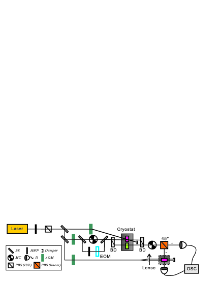
The experimental scheme is shown in Fig. 2. The laser should be wavelength tunable and have a linewidth well below 1 MHz. Using a polarization beam splitter (PBS) and a half-wave plate (HWP), the light’s polarization can be tuned to maximal absorption for a Nd3+:YVO4 crystal. The top acousto-optical modulators (AOM) shift the laser frequency to be on-resonance with to serve as the coupling light. The middle of the AOM sweep of the laser frequency around serves as the pump light. The mechanical chopper (MC) before the BD turns the strong pump light off during the detection cycle. The input pulse is generated using a 15-GHz EOM and the light’s polarization is rotated to by the HWP, where and denote horizontal and vertical polarization state, respectively. To show that the wavefronts actually do travel at the speed of independently of the Nd3+ ions, we use a reference pulse traveling through a pure YVO4 crystal. The beam displacer (BD) separates and polarized light. The polarized probe light is sent through the Nd3+:YVO4 crystal (top, red filled) such that it overlaps with coupling light at a small angle. The polarized probe light is sent through the pure YVO4 crystal (bottom, green filled) of the same length, . The Nd3+:YVO4 crystal’s axis is aligned in the horizontal direction and the YVO4 crystal’s axis is aligned in the vertical direction to avoid birefringence. All of the crystals are placed in a cryostat with a temperature 3 K and a magnetic field 0.5 T. Then and polarized light are combined using the BD and then undergo polarization dependent detection. The MC after the BD is used to block light to protect the filter and detectors during the pumping procedure of the first Nd3+:YVO4 crystal. The transmitted light intensities for the and polarizations are recorded using an oscilloscope (OSC). The intensities are given by
| (2) | |||
| (3) |
where
| (4) | |||
| (5) |
and IFT means Inverse Fourier Transformation. Note that the phase velocity is the relevant quantity for interference, which is the same in a pure crystal and a low-doping crystal. If the polarized field and polarized field arrive at the same time, the interference shall give an ideal near-to-zero output for in the first nanoseconds.
To totally eliminate the main fields with the central frequency components, which experience greater phase shifts, another Nd3+:YVO4 crystal with length is placed before the detectors for polarized light. The crystal’s axis is aligned in the direction for maximal absorption. It acts as a strong absorption filter which can be characterized by
| (6) |
This is the special case of Eq. (1) with . is controlled by the pump light produced by the lower AOM in Fig. 2. In the following text, we refer to this Nd3+:YVO4 crystal as the “filter” for simplicity. With the filter present, the recorded intensity for is given by
| (7) |
where .
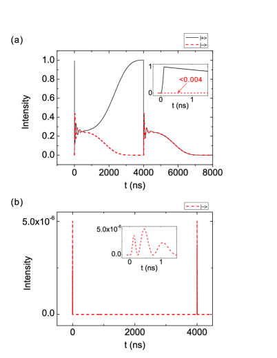
To show the advantages of having the filter present, the simulation results using FFT with 0.01-ns sampling resolution are shown in Fig. 3 with m and for panel (a) and m and m for panel (b). The input pulse is the same as before and was chosen to be . For Fig. 3(a), we first note that the polarized light remains the same as the input square pulse after traveling in the pure YVO4 crystal as mentioned above. When the polarized wavefronts decay, the polarized light starts to dominate. Therefore, (black solid line) and (red dashed line) have nearly the same intensity. Then, the polarized main fields slowly increase. rises with it and decays, because the delayed main fields are still almost entirely in the phase with the polarized light. After 4 s, the polarized pulse ends, and and share exactly the same intensities. It can be seen that rises immediately after , but is suppressed during the first nanosecond. This shows that polarized wavefronts travel at the same speed as the polarized light in the pure YVO4 crystal. If this were not the case, would rise at the same time and with the same intensity as , because only () polarized light would present and there would be no interference between the two paths for the given delay time. A time delay between the arrival of and polarized light would lead to a remarkable intensity for , which can be estimated to be . However, for Fig. 3(a) with no filter present, can grow to 0.004 in the first nanoseconds with no delay for either path. Therefore, it becomes impossible to measure with subpicosecond accuracy.
The transmission with the filter is shown in Fig. 3(b). is the same as that in Fig. 3(a) and is not shown in Fig. 3(b). Because the filter has wideband absorption, only photons with frequencies far-detuned from the resonance are transmitted. The main fields are totally absorbed by the filter, and only rising and falling edges at and remain. For all time scales, at most can grow to in the first nanoseconds after and . Because the remaining far-detuned light experiences little phase shift, there is near-perfect interference between the two paths. Therefore, whenever there is an intensity larger than recorded for , we may infer that there is a time delay between the arrival of and polarized light. Moreover, the interference yields the same results when the first Nd3+:YVO4 crystal acts as a two-level system, which is the fast-light regime.
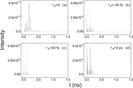
To accurately determine the speed of wavefronts using this method, let m, m, and which is roughly the inhomogeneous broadening of the Nd3+ ions. Thus, the lower AOM in Fig. 2 may not be necessary. The propagation time in the first crystal is 400 ps. A time delay between the polarized light and polarized light is artificially introduced. Let . This means the polarized light will fall behind (move ahead of) of the polarized light by for (). The output intensities calculated using FFT with 0.1-ps sampling resolution with 0, -40 fs, 40 fs and 4 ps are shown in Figs. 4(a)-(d), respectively. Clearly with 40 fs is much greater than that without delay. The longer the delay, the greater the that can be obtained. Whether the polarized light is faster or slower than the polarized light has little effect on the output. This is shown in Fig.s 4(b) and 4(c). The sign of may be experimentally identified by introducing a compensation delay in either path.
Considering a realistic detector with a bandwidth of 5 GHz, the recorded power for polarized light can be estimated by averaging the results in Fig. 4(b) for every 0.2 ns. The maximum outputs are and for Figs. 4(a)-(d), respectively. The power of probe light can be chosen to be 1 mW in the experiment. Therefore, when the power of polarized light is recorded with a value over 2.5 pW, we can conclude that there is a speed difference of for the two paths, which is approximately . With the parameters chosen here, a bound of less than 10-4 on the accuracy of the wavefronts’ speed can be experimentally determined.
The highest speed resolution with this scheme is not limited to which depends on several parameters. The first is the rise time of the input pulse, which is determined by the modulation method. Because , the smaller is, the more sensitive is to . The faster the signal rises, the harder they can “see” Nd3+ in the Nd3+:YVO4 crystal. The second is the length of the first crystal, , which determines the transmission time, . Because , for a larger , the speed difference can be determined more precisely. Third, detectors with better low-intensity responses can resolve a smaller . Note that the rise time of the detectors is not so important in this scheme because only the maximal intensity is of interest rather than the absolute time that the signal rises. Therefore, this method can determine the speed of the precursor to an accuracy of a given lower bound with better experimental conditions. Compared with previous works which determine the speed of information to an accuracy of about 0.1 by direct intensity recording Gauthier05 ; Gauthier03 , our scheme shall give more accurate measurements.
To summarize, we propose an interference scheme for accurately measuring the speed of wavefronts in an optically pumped Nd3+:YVO4 crystal. The simulation results computed with linear susceptibility of EIT medium show that the arrival time of wavefronts is independent of the strong dispersions caused by Nd3+ ions. Considering the current available modulation and detection technologies, the pure YVO4 crystal is treated as an infinite fast-response medium like the vacuum, so the wavefronts’ speed we are measuring is . In principle, with a powerful wideband filter and single-photon detectors with extremely low noise, the precursors which travel at the speed of in a Nd:YVO4 crystal also can be identified with our scheme. This scheme can be carried out in other systems where no background wideband medium is present, such as cold atoms and room temperature atoms. The conclusion can be made general as the ideal step-rising wave fronts travel at exactly the same speed in all materials. This scheme provides an approach to accurately measure the arrival time of precursors in various systems with realistic detecting systems. Future experimental measurements will provide a strict test of whether the information velocity with medium violates the Einstein causality. This work bridges the gap between the ideal concepts of precursors and the real pulses with finite rise (fall) time by showing an accurate boundary.
This work was supported by the National Basic Research Program (2011CB921200), National Natural Science Foundation of China (Grant Nos. 60921091 and 10874162).
References
- (1) A. Einstein, Ann. Phys. 17, 891 (1905).
- (2) Michael D. Stenner et al., Nature 425, 695 (2003).
- (3) Rorbert W. Boyd et al., Science 326, 1074 (2009).
- (4) L. J. Wang et al., Nature 406, 277 (2000).
- (5) Matthew S. Bigelow et al., Science 301, 200 (2003).
- (6) Gunnar Dolling et al., Science 312, 892 (2006).
- (7) George M. Gehring et al., Science 312, 895 (2006).
- (8) A. Sommerfeld, Ann. Phys. 44, 177 (1914).
- (9) L. Brillouin, Ann. Phys. 44, 203 (1914).
- (10) A english transilation of Sommerfeld1914 ; Brillouin1914 can be found in a book by L. Billouin, Wave Propagation and Group Velocity (Acadamic Press, New York, 1960).
- (11) R. Albanese et al., J. Opt. Soc. Am. A 6, 1441 (1989).
- (12) S.-H. Choi et al., Phys. Rev. Lett. 92, 193903 (2004).
- (13) Heejeong Jeong, and Shengwang Du, Opt. Lett. 35,124 (2010).
- (14) J. F. Chen et al., Phys. Rev. Lett. 104, 223602 (2010).
- (15) J. Aaviksoo et al., Phys. Rev. A. 44, R5353 (1991).
- (16) Éric Falcon et al., Phys. Rev. Lett. 91, 064502 (2003).
- (17) Heejeong Jeong et al., Phys. Rev. Lett. 96, 143901 (2006).
- (18) Shengwang Du et al., Opt. Lett. 33, 2149 (2008).
- (19) William R. LeFew et al., Phys. Rev. A. 79, 063842 (2009). Heejeong Jeong et al., Phys. Rev. A. 79, 011802(R) (2009). Bruno Macke et al., Phys. Rev. A. 80, 011803(R) (2009). J. F. Chen et al., Phys. Rev. A. 81, 033844 (2010).
- (20) Dong Wei et al., Phys. Rev. Lett. 103, 093602 (2009).
- (21) Shanchao Zhang et al., Phys. Rev. Lett. 106, 243602 (2011).
- (22) Hugues de Riedmatten et al., Nature 456, 773 (2008).
- (23) S. R. Hastings-Simon et al., Phys. Rev. B. 77, 125111 (2008).
- (24) Mikael Afzelius et al., J. Lumin. 130, 1566 (2010).
- (25) Michael Fleischhauer et al., Rev. Mod. Phys. 77, 633 (2005).
- (26) The refractive index is computed with Sellmeier equations provided by Fujian Castech Crystals, Inc.
- (27) Michael D. Stenner et al., Phys. Rev. Lett. 94, 053902 (2005).