Mesoscopic cross–film cryotrons:
Vortex trapping and
dc–Josephson–like oscillations of the
critical current
Abstract
We investigate theoretically and experimentally the transport properties of a plain Al superconducting strip in the presence of a single straight current-carrying wire, oriented perpendicular to the superconducting strip. It is well known that the critical current of the superconducting strip, , in such cryotron–like system can be tuned by changing the current in the control wire, . We demonstrated that the discrete change in the number of the pinned vortices/antivortices inside the narrow and long strip nearby the current-carrying wire results in a peculiar oscillatory dependence of on .
pacs:
74.25.F- 74.25.Sv 74.78.-w 74.78.NaI Introduction
The original idea to control the resistance of a long superconducting (S) wire by means of a magnetic field generated by a coil wound locally over the wire, was proposed by Buck in 1956.Buck-56 If the magnetic field inside the solenoid with permanent driving current exceeds the critical field of the central type–I superconducting wire, superconductivity will be completely suppressed and this device (cryotron) will be switched from a low-resistive state to a high-resistive state. Further investigations in the 1960’s deGennes-66 ; Bremer-62 ; Lock-62 ; Newhouse-69 revealed that the cryotrons can be potentially used as superconducting computer elements (switches, binary adders, shift registers, AND/OR gates etc). However the performance of such elements at high frequencies was found to be worse than ordinary semiconducting chips, since the cryotrons were rather slow and energy-consuming. Furthermore, the miniaturization of cryotron–like devices, which appears to be important for reducing the characteristic time constant, was very limited at those times.
Revival of interest to superconductor–electromagnet (S/Em) hybrids came in the 1990’s in connection with the problem of the influence of a spatially-modulated magnetic field on superconductivity. The development of advanced techniques for material deposition and lithographic methods have made it possible to fabricate composite structures with controlled arrangement of superconducting, normal metallic, ferromagnetic and insulating layers at micron and submicron levels. Pannetier et al. Pannetier-95 demonstrated that the dependence of the critical temperature on the applied magnetic field for such a hybrid system consisting of a plain Al film and a lithographically defined array of parallel metallic lines can be nonlinear and even non-monotonous in contrast to a plain superconducting film in a uniform magnetic field.Tinkham Such tunability of the dependence by the stray field of the meander–like wire reflects directly the controllable modification of the standard Landau spectrum for the order parameter (OP) wave function in a periodic magnetic field.Peeters ; Aladyshkin-PRB-03 ; Aladyshkin-PRB-06 It is worth noting that keeping the nonuniform magnetic field of the control coils/wires requires expenditure of energy and may result in parasitic heating effects. Therefore, later on the interest was turned to superconductor–ferromagnet (S/F) hybrids since the inhomogeneous magnetic field in S/F systems, conditioned by the nonuniform distribution of magnetization, can be obtained without energy costs. The influence of a nonuniform magnetic field produced by ferromagnetic elements on nucleation of superconductivity and low-temperature properties of superconducting specimens was studied intensively for flux-coupled S/F hybrids during the last two decades (see reviews Lyuksyutov-AdvPhys-05 ; Velez-JMMM-08 ; Aladyshkin-SuST-09 and references therein). We would like to note that the amplitude of the stray magnetic field and its profile are dictated by the saturated magnetization of the ferromagnet and by the shape of the ferromagnetic elements, which eventually restricts the flexibility of the S/F hybrids.
In the present paper we report on a so far unexplored limit of a cryotron–like system at micro- and nanoscales bringing together the ideas and approaches developed for both S/Em and S/F hybrids. With that purpose we fabricated a composite structure consisting of a type-II superconducting strip and a single straight current-carrying S wire oriented perpendicular to the strip. Since the stray magnetic field of the straight wire is maximal near the wire and it decays approximately as at large distances from the wire, one can expect that only a small part of the superconducting strip in close vicinity to the wire will be affected by the nonuniform magnetic field.Sonin A simple change in the current in the wire, , gives us the opportunity to control the maximal value of the magnetic field, , generated by the current in the control wire. By varying one can create different states with partially and completely suppressed superconductivity in the considered cross–film cryotron. Thus, the main point of our research is to “scan” all possible intermediate states lying between uniform superconductivity (for small ) and fully depleted superconductivity (for large ) and to study the effect of the transitions between various superconducting states on the critical current for mesoscopic type–II cross–film cryotrons.
II Theory
II.1 Model
To simulate the onset of vortex dynamics in the superconducting strip in the field of the current-carrying wire (i.e. in the cross–film cryotron) under the action of the transport current we use a time–dependent Ginzburg–Landau model.IvlevKopnin-84 The thickness of the superconducting strip is assumed to be infinitely small, so the effective magnetic field penetration length exceeds substantially the lateral dimensions of the superconducting sample ( is the London penetration depth). Consequently, both the magnetic field and the vector potential are determined solely by external sources. We use the following units: for time, the coherence length at temperature for distances, for the vector potential and for the current density, where and are the conventional parameters of the Ginzburg-Landau expansion, , is the critical temperature at , and are charge and the effective mass of carriers, is the normal state conductivity. Then the time–dependent Ginzburg–Landau equations take the form Kapra-11
| (1) | |||
| (2) |
Here is the normalized order parameter (OP), is the dimensionless electrical potential, is the dimensionless density of superconducting currents, is the rate of the OP relaxation, c.c. stands for complex conjugate. To complete the problem we apply the boundary conditions
| (3) |
which seems to be natural for the superconductor/vacuum or superconductor/insulator interfaces, is the normal vector to the sample’s boundary , is the normal component of the inward (outward) flow of the external current. To detect a vortex on the grid cell corresponding to the certain grid node (), we use the following criterion:Melnikov-PRB-02
| (4) |
, is the argument of the complex number , belonging to the interval (-, ]. If , there is a vortex in the cell, while corresponds to an antivortex. It is important to note that we define the vortex (antivortex) as a position of the singularity of the OP phase, , however the direction, in which the superconducting currents circulate around the center of the vortex (antivortex), depends on the charge of carriers (i.e. the sign).
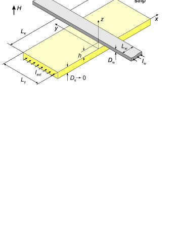
To facilitate further comparison between theory and experiment (Section III), for our modeling we choose the parameters, typical for mesoscopic Al-based superconductors: the coherence length m at , length and width of the strip m and m, width and thickness of the current-carrying wire m and m, and the separation between the strip and the wire m (Fig. 1).
II.2 Mixed state in cross-film cryotron in equilibrium at
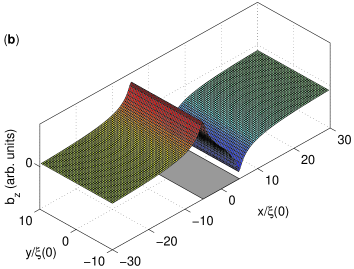
The stray field generated by the control wire is uniform across the superconducting bridge (in the direction, Fig. 1b). However in the direction the field is substantially inhomogeneous with the –component reaching its extreme values near the edges of the current-carrying wire. The increase in the control current leads to a gradual enhancement of the maximal value. This eventually results in the local suppression of the energy barrier for vortex penetration from the edges of the strip near the maxima. These regions play the role of predefined gates for vortex entry.
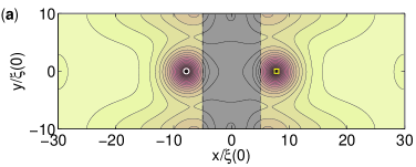
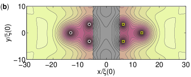
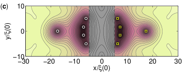
The stray field of the control wire acts as (i) a tunable source of vortices and antivortices and, (ii) a vortex trap which prevents vortex-antivortex pairs from their mutual annihilation and the escape from the superconducting bridge. The latter follows from the distribution of the screening superconducting currents induced by the current-carrying wire (see Fig. 3b). Indeed, the different signs of the component of near the top and bottom edges of the strip mean that the Lorentz force acting on the vortex (antivortex) near these edges will be oriented in such a way in order to push the vortex (antivortex) to the inner part of the strip. In the absence of an external magnetic field the appearance of a vortex should be accompanied by the formation of a symmetrically positioned antivortex and the number of vortex-antivortex pairs increases as increases (Fig. 2). Since the field roughly decays inversely proportional to the distance from the wire, the vortices and antivortices are also distributed non-uniformly: the closer to the wire, the smaller the distance between two vortices (antivortices) is.
II.3 Critical current of cross-film cryotron at
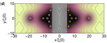
Depending on the magnitude of the bias current , injected into the superconducting strip, there are two distinct regimes. After applying a small bias current the disturbed vortex and antivortex tend to relax into a new stationary configuration. This state with motionless vortex-antivortex pairs is characterized by the absence of an electrical field inside the superconductor (except for tiny regions near the boundaries where the current injection takes place) and by a zero voltage drop. If exceeds the critical current , the stability of the vortex-antivortex ensemble breaks down: vortex and antivortex periodically in time enter and exit into/from the superconductor. This means that the sample has switched to a dissipative regime. The calculated dependencies at for different temperatures are shown in Fig. 3a. We see that decays with oscillations as sweeps and the oscillations become more pronounced at high temperatures.
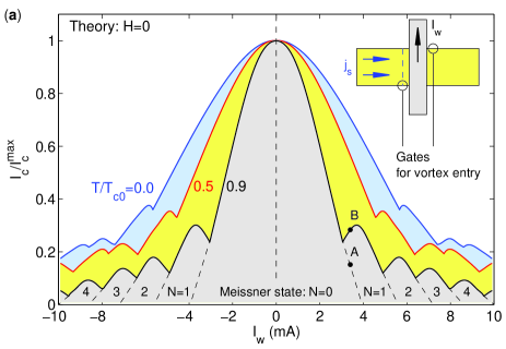
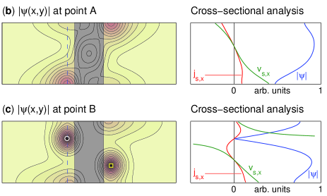
We can explain the appearance of the oscillations as follows. If and , superconductivity will survive until the injected current density exceeds the depairing limit. For nonzero the transition from the non-dissipative state to the resistive regime occurs via permanent formation of vortex-antivortex pairs at the opposite edges of the superconducting bridge and their motion across the bridge (see inset in Fig. 3). Due to the superposition of the injected current and the currents, induced by the wire, the limit for the vortex-antivortex pair generation can be reached at smaller values of the bias current; therefore monotonously decreases as increases. A further increase in leads to (i) a decrease in the threshold value of the bias current required for the creation of the first vortex, and (ii) an enhancement of the trapping potential for vortices. Both consequences make it possible to stabilize the vortex-antivortex pair in the presence of the transport current (Fig. 3c). The self-currents generated by the vortex and antivortex partly compensate the superflow conditioned by the bias current near the regions with suppressed OP wave function. Therefore these “gates” will be closed and the formation of new vortices and antivortices will be impeded unless the maximal value for supercurrent velocity , which is proportional to , again reaches its critical value at the strip edges. This means that after the first vortex-antivortex pair is trapped, the critical current will be larger than that in the Meissner state. Then this process is repeated periodically as increases, resulting in periodic variations in . Thus, the discrete change in the number of the pinned vortices and antivortices in the superconducting strip of a finite width can be identified by considering the position of the cusps on the curve. In contrast to the oscillations observed in mesoscopic superconducting squares in a uniform magnetic field,Vololazov-PRB-2005 the nonuniform magnetic field gives us the possibility to see the quantization effects in a long superconducting strip, due to the confinement potential along the strip produced by the control wire.
The absolute value of the magnetic flux piercing a half of the superconducting strip,
| (5) |
is a linear function of . In a certain sense the oscillations of the critical current of the cryotron as (or ) varies, are similar to the standard Fraunhofer pattern describing the dependence of the critical current of a Josephson junction on the total magnetic flux through the junction area.BaronePaterno-82 ; Abrikosov-88 The built-in field of the wire guarantees reversible entrance of vortices and antivortices into the superconducting strip as increases, and the tunable modification of the distribution of the OP phase in the restricted part of the strip by the trapped vortices and antivortices. This area with partly suppressed superconductivity near the control wire acts like an effective weak link, since the vortex dynamics in this area determines the flow of the bias current and the resistance of the entire strip.
II.4 Mixed state and critical current of cross-film cryotron at
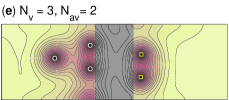
The external magnetic field , applied perpendicularly to the sample’s plane, breaks the symmetry between vortex and antivortex since the total magnetic flux piercing the sample is not zero anymore. As a result, the entrance of a new vortex is not generally accompanied by the entrance of an antivortex: the numbers of trapped vortices and antivortices, and , may differ in contrast to the previously considered case .
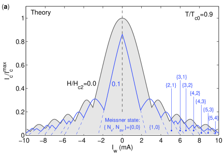
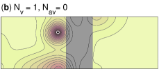
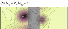
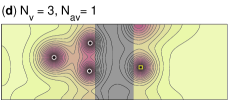
The results of the calculations for and at and are compared in Fig. 4a. It is clear that the oscillating behavior in the vs. remains even in the presence of the applied magnetic field. Since the constructive superposition of (i) the injected current, (ii) the currents induced by the wire and (iii) the currents induced by the external field, enhances the local flow of superconducting condensate, the conditions for vortex entry will be fulfilled at smaller values. This results in a shift of all the cusps on the dependence towards to zero. The non-equivalence between vortices and antivortices allows us to get new stable states of reduced symmetry (Fig. 4b-e) which are forbidden for the symmetrical sample at . The transition between such states sweeping are accompanied by additional cusps, which leads to more complex oscillatory properties of the on dependence.
III Experiment and discussion
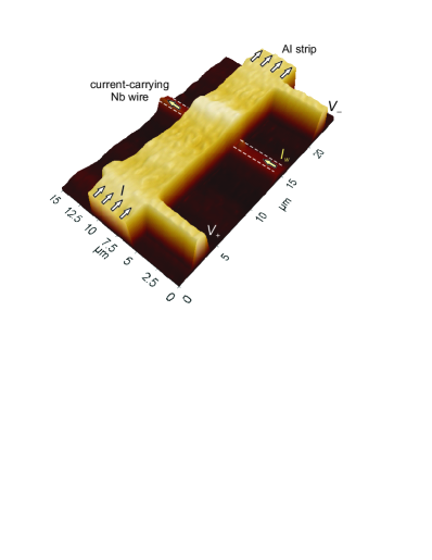
To study the transport properties of the mesoscopic cross-film cryotron, we fabricated the hybrid structures consisting of a m wide and 120 nm thick superconducting Al strip on top of a 1.5 m wide and 50 nm thick current-carrying Nb wire. The Nb thin film was deposited via dc magnetron sputtering at a rate of 2.5 nm/s on an oxidized Si substrate at room temperature under the pressure of Ar plasma of 6 mbar. The Nb wire was fabricated by e-beam lithography in combination with argon ion milling. The Al film was grown in a molecular-beam epitaxy apparatus at a rate of 0.2 nm/s at room temperature and nominal pressure of mbar. The Al strip was patterned by standard e-beam lithography, subsequent evaporation and lift-off technique. A 120 nm thick Ge layer separates the two metals from each other to avoid electrical contact between them. We tested more than 30 identical hybrid samples prepared at different times but under similar conditions. At least 10 samples have no problems with electrical leakage, since the applying a voltage between Al strip and Nb wire leads to an absence of detectable current. It gives us a lower limit on the contact resistance of the order of 5 M. An Atomic Force Microscopy (AFM) image of the sample is shown in Fig. 5.
Considering the dependence of the sample resistance on and its displacement upon varying , one can compose the phase transition line shown in Fig. 6b. By identifying this line with the temperature dependence of the critical field of surface superconductivity , we estimated K, the upper critical field Oe and the coherence length nm extrapolated to . The mean free path nm can be obtained from the value of the normal resistivity at low temperatures according to the formula:Fickett-71 m2. The nm value gives us the London penetration depth and the effective magnetic field penetration depth nm and nm respectively in dirty limit at . All obtained values are in accordance with previous studies on thin film Al structures.Gillijns-07
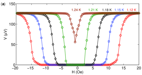
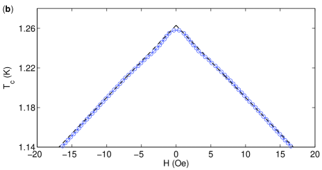
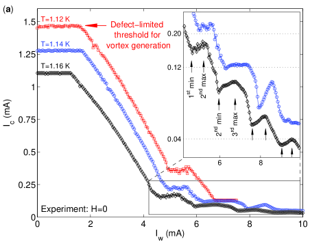
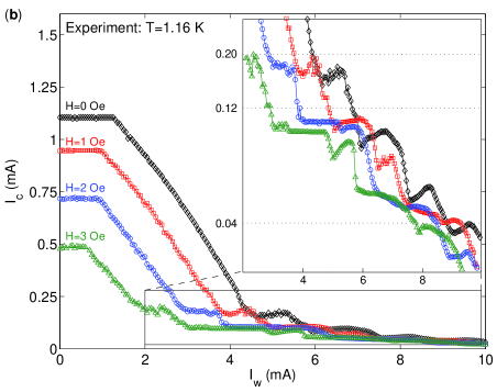
Figure 7a shows the of the Al strip as a function of the current in the control Nb wire, measured at and different temperatures close to . Experimentally the critical current was determined from the isothermal current – voltage dependencies for different voltage criteria (from 0.1 up to 10 between the two voltage contacts at a distance 20 micron) for the measured voltage drop.Campbell-Evetts For our measurements the accuracy of the determination of the critical current was 3 A. This means that within the interval 2 we observed a sharp transition from the superconducting state (typical noise level of the order of V) to the resistive state. The plateau in might be associated with the influence of sample imperfections, which facilitate the formation of vortices near defects even in zero magnetic field at current densities smaller than the theoretical limit. In accordance with our simulations the monotonously decreasing part of has to be attributed to the transition from the Meissner state to the resistive state with a single moving vortex-antivortex pair. The next stages correspond to the stabilization of the first and all subsequent vortex-antivortex pairs in the sample. The switching between these states at varying corresponds to the local minima. We clearly observed the reproducible oscillations of the critical current for all measured samples.
The effect of the external field is illustrated by Fig. 7b. We observed the anticipated shift of the monotonously decreasing part in towards smaller values, conditioned by the constructive superposition of the injected current, the currents induced by the wire and by the external field. This ensures that the conditions for the first vortex entry will be fulfilled at smaller values. It is interesting to note that the shape of the oscillating curves becomes more complicated as increases. We suppose that the external-field-induced modification of reflects the formation of exotic non-symmetrical vortex states and their depinning under the action of the bias current.
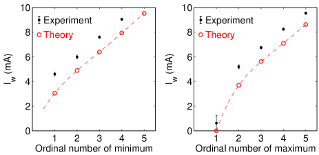
To compare theory and experiment, we plot the positions of the minima and maxima in the dependence at (Fig. 8). It is easy to see that our simple model describes both the general oscillating behavior for the dependence for real sample and the observed period quite well. The fact that all theoretical points in Fig. 8 lie below the experimental data, may be caused, e.g., by a nonuniform current distribution in the control wire, or by a small difference between the parameters of the model problem and the dimensions of the tested samples. Nevertheless using the estimated period mA, one can calculate the change in the magnetic flux through the half of the superconducting strip and corresponding to the appearance of the vortex-antivortex pair: .
In this paper we have reported on the first results obtained for the prepared S/Em samples. We note that the oscillatory behavior of the critical current as a function of was found to be reproducible for all measured samples, which had identical geometry and size as the presented device. However the issues concerning the influence of the dimensions of the superconducting strip and the current-carrying wire on the oscillations remain unaddressed.
IV Conclusion
We studied the transport properties of a hybrid system consisting of a superconducting strip and a current-carrying wire, oriented perpendicular to the strip. The stray field, generated by the control wire, makes it possible to tune the transport properties of the long superconducting strip locally by means of creation and pinning of vortices and antivortices. This area, where vortices and antivortices become confined, plays the role of a “bottleneck” for the transport current, since the motion of vortices and antivortices is the main source of the dissipation. Thus, the peculiar configurations of vortex-antivortex pairs determine the critical current of the S strip. The transition between different stable vortex patterns upon varying results in an oscillatory dependence of on . The observed effect, which looks similar to the Fraunhofer oscillating pattern for conventional Josephson junctions, can be potentially interesting for the design of superconducting interferometer devices based on S/F or S/Em hybrid structures.
This work was supported by the Methusalem Funding of the Flemish Government, the NES – ESF program, the Belgian IAP, the Carl-Zeiss-Stiftung and the Deutsche Forschungsgemeinschaft (DFG) via the SFB/TRR 21, the Russian Fund for Basic Research, RAS under the Program “Quantum physics of condensed matter” and Federal Target Program “Scientific and educational personnel of innovative Russia in 2009–2013”. A.V.S, W.G. and J.V.d.V. acknowledge support from F.W.O.
References
- (1) D.A. Buck, Proc. IRE, 44, 482 1956.
- (2) P.G. de Gennes, Superconductivity of Metals and Alloys (W.A. Benjamin Inc., New York, 1966).
- (3) J.W. Bremer, Superconductive Devices (McGraw-Hill, New York, 1962).
- (4) J.M. Lock, Rep. Prog. Phys. 25, p. 37 (1962).
- (5) V.L. Newhouse, in Superconductivity, ed. R.D. Parks (Marcel Dekker, New York, 1969), Vol. 2, Chap. 22.
- (6) B. Pannetier, S. Rodts, J.L. Genicon, Y. Otani and J.P. Nozieres, chapter in Macroscopic Quantum Phenomena and Coherence in Superconducting Networks, Eds. C. Giovannella and M. Tinkham, (World Scientific, Singapore, 1995), pp. 17–24.
- (7) E.g., M. Tinkham, Introduction to Superconductivity (2nd ed., McGraw-Hill, New York, 1996).
- (8) F.M. Peeters and P. Vasilopoulos, Phys. Rev. B 47, 1466 (1993); I.S. Ibrahim and F.M. Peeters, Phys. Rev. B 52 17321 (1995).
- (9) A.Yu. Aladyshkin, A.I. Buzdin, A.A. Fraerman, A.S. Mel’nikov, D.A. Ryzhov, and A.V. Sokolov, Phys. Rev. B 68, 184508 (2003).
- (10) A.Yu. Aladyshkin and V.V. Moshchalkov, Phys. Rev. B 74, 064503 (2006).
- (11) I.F. Lyuksyutov and V.L. Pokrovsky, Adv. Phys. 54, 67 (2005).
- (12) M. Vélez, J.I. Martín, J.E. Villegas, A. Hoffmann, E.M. Gonzalez, J.L. Vicent, and I.K. Schuller, J. Magn. Magn. Mater. 320, 2547 (2008).
- (13) A.Yu. Aladyshkin, A.V. Silhanek, W. Gillijns, and V.V. Moshchalkov, Supercond. Sci. Technol. 22, 053001 (2009).
- (14) A similar effect of the stray magnetic field for the S/F bilayers was considered by E.B. Sonin, Sov. Tech. Phys. Lett. 14, 714 (1988).
- (15) B.I. Ivlev and N.B. Kopnin Usp. Fiz. Nauk 142, 435 (1984); B.I. Ivlev and N.B. Kopnin, Adv. Phys. 33, 47 (1984).
- (16) A.V. Kapra, V.R. Misko, D.Y. Vodolazov, and F.M. Peeters, Supercond. Sci. Technol. 24, 024014 (2011).
- (17) A.S. Mel’nikov, I.M. Nefedov, D.A. Ryzhov, I.A. Shereshevskii, V.M. Vinokur, and P.P. Vysheslavtsev, Phys. Rev. B 65, 140503(R) (2002).
- (18) E.g., D.Yu. Vodolazov, F.M. Peeters, M. Morelle, and V.V. Moshchalkov, Phys. Rev. B 71, 184502 (2005).
- (19) A. Barone and G. Paterno, Physics and Applications of the Josephson effect (John Wiley & Sons, New York, 1982).
- (20) A.A. Abrikosov, Fundamentals of the Theory of Metals, (North-Holland, Amsterdam, 1988).
- (21) F.R. Fickett, Cryogenics 11, 349 (1971).
- (22) W. Gillijns, A.Yu. Aladyshkin, A.V. Silhanek, and V.V. Moshchalkov, Phys. Rev. B 76, 060503(R) (2007).
- (23) A. M. Campbell and J.E. Evetts, Critical Currents in Superconductors (Taylor & Francis Ltd., London, 1972).