Relation Between Local Temperature Gradients and the Direction of Heat Flow in Quantum Driven Systems
Abstract
We introduce thermometers to define the local temperature of an electronic system driven out-of-equilibrium by local ac fields. We discuss the behavior of the local temperature along the sample, showing that it exhibits spatial fluctuations following an oscillatory pattern. We show explicitly that the local temperature is the correct indicator for heat flow.
keywords:
quantum transport , heat flow , driven systems , effective temperaturePACS:
65.90.+i1 Introduction
Heat transport at the meso and nano scale is subject of wide increasing interest at present and hence it is subject of intense research. There are basically two motivations for this. On the one hand, the technological trend towards miniaturization of electronic circuits pushes for a better understanding of the mechanisms for heat production and energy flow at the microscopic level. On the other hand, from a more general point of view, one is often faced with situations in which the very fundamental concepts of standard Statistical Mechanics and Thermodynamics are put into test. This is for instance the case when the system under consideration is driven out of equilibrium.
In a recent work, [1] we have addressed the issue of identifying effective temperatures in the context of transport in electronic quantum systems driven out of equilibrium by external (periodic) pumping potentials. Examples of this type of systems are quantum dots with ac voltages acting at the walls (quantum pumps). These systems can not only dissipate energy in the form of heat, but can also pump energy between the different reservoirs, generating refrigeration. We have defined a “local” temperature along these set ups by introducing a thermometer, i.e. a macroscopic system which is in local equilibrium with the system, even when the system itself is out of equilibrium. This is the thermal analogue of voltage probe discussed in Ref. [3, 4].
The aim of this work is to further investigate the concept of local temperature in quantum driven systems. In particular, our goal is to show that indeed such parameter signals the direction of heat flow, acting as a bona fide temperature.
2 Model and theoretical treatment
Our setup, including the device with the driven system in contact to reservoirs and thermometer is described by the Hamiltonian:
| (1) |
The piece contains the term describing the central system () with the AC fields, as well as terms corresponding to left () and right () reservoirs with the ensuing contacts and . The term represents the thermometer. It consists in a macroscopic system weakly coupled to a given point of , through a contact described by . It behaves like a reservoir with a temperature that is determined by the condition of a vanishing heat flow between it and . This is the thermal counterpart of a voltage probe (see Ref. [3, 4]). All the reservoirs are modeled by systems of non-interacting electrons with many degrees of freedom: , being . The corresponding contacts are , where denotes the coordinate of at which the reservoir is connected. We take into account the non-invasive property of the thermometer [3] by treating at the lowest order of perturbation theory when necessary. We leave for the moment undetermined as much of the coming discussion is model independent.
The dynamics of the system is best described within the Schwinger-Keldysh Green functions formalism. This involves the calculation of the Keldysh and retarded Green functions,
| (2) |
where the indexes denote spatial coordinates of the central system. These Green functions can be evaluated after solving the Dyson equations. For ac driven systems, it is convenient to use the Floquet Fourier representation of these functions [5]:
| (3) |
where is the frequency of the ac fields.
3 Defining the local temperature
As we did in Ref. [1] we define the local temperature as the value of (i.e the temperature of the probe) such that heat exchange between the central system and the probe vanishes. As shown in [2], given without many-body interactions, the heat current from the central system to the thermometer can be expressed as ()
| (4) |
where , is the spectral function that determines the escape to the reservoir , and , is the Fermi function, which depends on the temperature and the chemical potential of the reservoir . Thus, the local temperature corresponds to the solution of the equation . In general, the exact solution must be found numerically, however, an exact analytical expression can be obtained within the weak-coupling and low-temperature regime.[1]
4 Results
In this section we present results for a central device consisting of non-interacting electrons in a one-dimensional lattice:
| (5) |
where denotes a hopping matrix element between neighboring positions on the lattice, and a driving term of the form:
| (6) |
with , being the position at where the local ac field is applied.
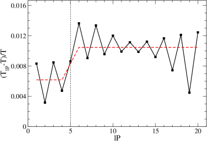
In Fig. 1 we show that the local temperature varies along the sample. As we discused in Ref. [1], the local temperature presents oscillations modulated by 2, being the Fermi vector of the electrons leaving the reservoirs. This oscillations are due to the coherent transport of the electrons through the device and account for scattering processes at the point of the structure where the ac voltage is applied.
4.1 Coarse-grained temperature and the direction for the heat flow
We now turn to explore the relation between this local temperature and the heat flow. In order to do this, it is necessary to connect this local microscopic temperatures to coarse grained temperatures for the two thermal regions in which is divided the sample. A left (l) region defined between the reservoir and the point at which the ac voltage is applied and a right (r) region defined between the point at which the ac voltage is applied and reservoir. Then, it is straightforward to define the mean temperature of these two regions as follows:
| (7) |
where l,r, while denotes the number of points contained in each of these regions. The mean temperatures for both regions are shown in Fig. 1.
We now turn to show that the difference between the coarse grained temperatures completely determine the direction of the heat flow as follows:
| (8) |
where for the case of the reservoirs , while is a thermal conductance which might depend on temperature and some of the parameters of the system.
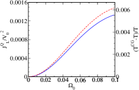
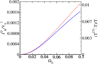
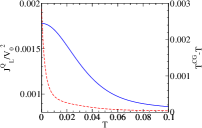
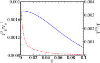
Results are shown in Fig. 2, as a function of the driving frequency (upper panel) and the temperature of the reservoirs (lower panel). The flow is defined positive when the heat flows to the reservoir. In the same figure, we show . This is indeed the expected situation in which the effective temperature is larger than the leads temperature and we see explicitly that the heat flow occurs as expected, from the “hot” sector (the system) to the colder one (the leads). In a pumping regime we expect to find situations in which heat can be extracted from one lead to pump it into the system, but this kind of regime is not possible with only one ac field acting on the system.
As we can see in the upper panel of Fig. 2, for increasing driving frequency , the difference between the coarse-grained temperature and the temperature of the reservoirs increases, and so does the heat current that flows into the reservoir. The proportionality constant between this two quantities is the thermal conductivity () that seems not to depend on the driving frequency , but further study is necessary in order to arrive to that conclusion.
In the lower panel of Fig. 2 we can see that for increasing temperature of the reservoirs, the difference decreases, and so does the heat current that flows into the reservoir. In this case, the proportionality constant between this two quantities does depend on temperature . The temperature difference decreases faster than the heat current so the thermal conductivity is an increasing function of , but further studies are necessary in order to determine the dependence on . The fact that goes to zero reflects the fact that at a high temperature, the effect of the driving becomes washed up and the sample becomes mainly heated due to the contact with a high temperature environment. This is in complete agreement with previous results obtained in a similar system. [1]
5 Conclusion
We studied the behavior of the local temperature in a quantum system driven out of equilibrium by one ac field. This quantity indicates a global heating of the sample, which manifests itself in the form of mean temperatures higher than the one of the reservoirs. The occurrence of oscillations in the local temperature is an indication of quantum interference, due to coherence in the energy propagation, in complete agreement with the results obtained in a similar system (see Ref. [1]). We showed that the difference between the mean temperature of the l (r) region of the sample and the one of the reservoirs defines the heat flow that enters the L (R) reservoir. In a pumping regime, we expect that the mean temperature of the region in contact with the reservoir from which heat is extracted shall be lower than the one of the reservoirs. This kind of regime is not possible in the studied system and will be subject of future investigation.
 |
 |
 |
 |
6 Acknowledgments
We acknowledge support from CONICET, ANCyT, UBACYT, Argentina and J. S. Guggenheim Memorial Foundation (LA).
References
- [1] A. Caso, L. Arrachea, G. S. Lozano, Phys. Rev. B 81, 041301(R) (2010).
- [2] L. Arrachea, M. Moskalets and L. Martin-Moreno, Phys. Rev. B 75, 245420 (2007).
- [3] H. L. Engquist and P. W. Anderson, Phys. Rev. B 24, 1151 (1981); T. Gramespacher and M. Büttiker, Phys. Rev. B 56, 13026 (1997); L. Arrachea, C. Naón and M. Salvay, Phys. Rev. B 77, 233105 (2008).
- [4] F.Foieri, L.Arrachea and M.J. Sanchez, Phys. Rev. B 79, 085430 (2009); F.Foieri and L.Arrachea, Phys. Rev. B 82, 125434 (2010).
- [5] L. Arrachea, Phys. Rev. B 72 125349 (2005) and Phys Rev. B 75, 035319 (2007); L. Arrachea, and M. Moskalets, Phys. Rev. B 74 245322 (2006).