Turn-key module for neutron scattering with sub-micro-eV resolution
Abstract
We report the development of a compact turn-key module that boosts the
resolution in quasi-elastic neutron scattering by several orders of magnitude
down to the low sub-µeV range. It is based on a pair of neutron
resonance spin flippers that generate a well defined temporal intensity
modulation, also known as MIEZE (Modulation of IntEnsity by Zero Effort). The
module may be used under versatile conditions, in particular in applied
magnetic fields and for depolarising and incoherently scattering samples. We demonstrate the power of
MIEZE in studies of the helimagnetic order in MnSi under applied magnetic
fields.
©(2011) American Institute of Physics. This article may be downloaded for personal use only. Any other use requires prior permission of the author and the American Institute of Physics.
The following article appeared in Applied Physics Letters and may be found at URL: http://link.aip.org/link/?apl/98/073505
Neutron scattering is an extremely powerful technique for studies of the dynamical properties of condensed matter systems. Prominent examples of great current interest concern the spin dynamics in transition metal and rare earth compounds and diffusive processes in soft matter systems such as proteins, liquid crystals and emulsions. A precondition to unravel some of the most important scientific challenges is the need for high energy and momentum resolution.
Conventional neutron scattering techniques such as triple-axis and time-of-flight spectroscopy provide momentum resolved energy resolutions of the order of 10 µeV. Backscattering reaches the sub-µeV regime, however sacrificing momentum resolution. This is contrasted by neutron spin-echo (NSE) methods Mezei (1972); Golub and Gähler (1987), which offer high energy and momentum resolutions in the low sub-µeV range – several orders of magnitude below the typical resolutions of conventional techniques. However, because NSE scattering uses polarised neutrons it is inherently sensitive to the depolarisation of the neutron beam. Therefore, it is technically very demanding to perform NSE measurements under applied magnetic fields or in depolarising samplesPappas et al. (2008, 2009) such as superconductors, ferromagnetsFarago and Mezei (1986) or protonated soft matter systems.
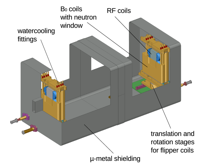
In this Letter we report the development of a turn-key module, the MIEZE box shown in Fig. 1. In combination with a polariser, a polarising analyser and a fast detector this box allows to improve the energy resolution in all types of neutron scattering instruments capable of studying quasi-elastic scattering, notably diffractometers, small-angle neutron scattering cameras and reflectometers (especially instruments for small and cold neutrons), down to the sub-µeV range. The module is based on the so-called MIEZE-I technique (Modulation of IntEnsity by Zero Effort, type I) Gähler et al. (1992); Köppe et al. (1996); Besenböck et al. (1998); Keller et al. (2002); Bleuel et al. (2006); Kawabata et al. (2006), where the modulation of the beam is performed upstream of the sample. Therefore, in contrast to NSE, the MIEZE module we describe may even be used under depolarising conditions in or around the sample. This routinely allows neutron scattering studies with the highest possible energy resolution in a wide range of materials.
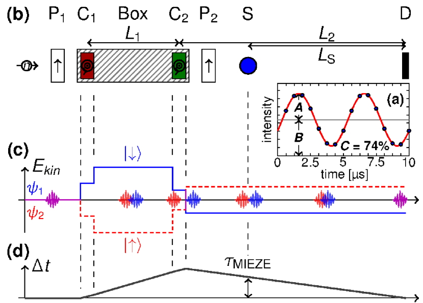
Qualitatively, the MIEZE-I technique is based on a harmonic intensity modulation of the neutron beam, where the contrast is given by the ratio of the amplitude to the average signal as shown in Fig. 2a. Using a phase-locked pair of two resonance spin flippersKeller et al. (2002); Arend (2007), which operate at slightly different frequencies, and , induces a slow rotation of the polarisation direction of the neutrons, which is subsequently converted into an intensity beating by means of a polarising analyser.
While former experiments with the MIEZE-I technique have been successful, we managed to implement MIEZE-I as a routine technique through a redesign of the neutron resonance spin flippers. Instead of wire-wound B0 coils we use electro-erosion machined coil windings where a better definition of the magnetic field boundaries is obtained. They consist of a specially selected Al alloy with much less small angle scattering and a higher transmissionArend (2007). Together with a more reproducible mounting of the RF coils this results in stable -flips over a wide range of RF frequencies with low small angle scattering background.
A description of the MIEZE-I principle pointing out its vicinity to TOF methods is illustrated in Fig. 2; for a proper quantum mechanical description we refer to the literature (cf Ref. Arend et al. (2004)). When a neutron arrives at the first spin flipper with its polarisation perpendicular to the static field in the flipper, the correlation volumes (or wave-packages) corresponding to the spin-up and spin-down spin states are prepared (cf Fig. 2 (c)). While the kinetic energy of the spin-down state increases, the kinetic energy of the spin-up state decreases. Therefore, the correlation volumes for the spin-down and spin-up states arrive at different times at the second resonance spin flipper placed at a distance behind the first spin flipper. This second spin flipper inverts the energy splitting of the spin states, reducing the kinetic energy of the spin-down state and increasing the kinetic energy of the spin-up state. Therefore the correlation volumes, overlap again at a distance behind the second spin flipper, given by where .
An analyser at an arbitrary position between the second spin flipper and the detector (the latter is located where the correlation volumes meet) projects out the intensity of the interference pattern of the spin-up and spin-down states. As the correlation volumes of the spin-up and spin-down states have different energies, the interference pattern exhibits the intensity modulation of contrast referred to above.
To explain how this intensity modulation may be exploited in experimental studies using two single neutron resonance spin flippers, we show in Fig. 2 (d) the delay between the two correlation volumes, . The correlation volumes probe the sample at different times with the delay given by Com , where 2 is the frequency of the resulting MIEZE signal, is the distance between sample and detector, and and are the mass and average velocity of the neutrons. By overlapping these volumes at the detector, one obtains a signal contrast which is directly proportional to the intermediate scattering function , i.e., the information on the dynamics on this time scale. Further, for quasi-elastic scattering with an assumed Lorentzian line shape with half-width , the normalised intermediate scattering function is given by Keller et al. (2002) , where corresponds to the intermediate scattering function of a purely elastically scattering sample.
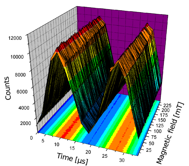
The MIEZE-I technique is similar to conventional neutron resonance spin echo (NRSE) methods, where the two spin flippers before the sample correspond to the first arm of an NRSE instrument. Moreover, the MIEZE time is equivalent to the spin echo time in NSE and NRSE instruments Keller et al. (2002). However, there is a distinct difference between MIEZE-I and NSE/NRSE. Placing the polarising analyser behind the second spin flipper and before the sample, the MIEZE-I technique becomes insensitive to effects of the sample or sample environment on the polarisation of the neutron beam, i.e. for example depolarisation or applied magnetic fields. This is demonstrated in Fig. 3, where the contrast of the direct beam is plotted versus a magnetic field up to 0.2 T and no effect on the signal contrast can be observed.
The MIEZE experiments were carried out at the diffractometer MIRA at FRM II using neutrons with a wavelength Å, i.e., a mean velocity . The first and second spin flipper being 0.9 m apart were operating at frequencies in the range and , respectively, providing a beating frequency in the range . The distance between the sample and detector was . Taken together MIEZE times could be accessed in a range . A 0.3 mm thick 6Li doped glass scintillator with a photomultiplier was used as a fast detector.
We note that the temporal and thus spatial separation of the spin-up and spin-down states makes MIEZE-I sensitive to path length differences between the first RF-flipper and the detector, e.g. due to the large divergence of the beam, the finite size of the sample or the finite thickness of the neutron detector. However, for the wavelength of 10.4 Å, frequencies in the range 46 kHz to 200 kHz for the MIEZE signal, typical sample sizes of 10 mm, and scattering angles of the order of a few degrees we measured with a standard sample used for resolution measurements a contrast reduction of less than 10% up to Å-1 being in agreement with the results of calculations of the path length and precession phase differences.
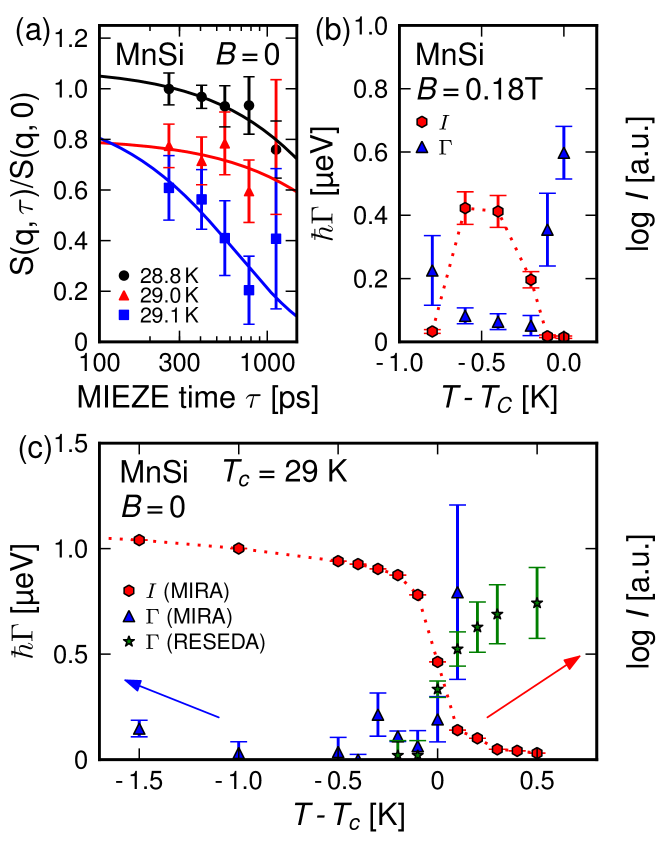
To demonstrate the power of MIEZE-I in studies of field-induced forms of magnetic order normally not accessible to NSE/NRSE, we have investigated the cubic B20 compound MnSi Ishikawa et al. (1976). MnSi orders helimagnetically below a transition temperature, in our case at . The large pitch of the helix Å implies that the associated magnetic Bragg peak at Å-1 can be accessed in a forward scattering configuration. Just below at , the A-phase is observed. Here a special form of magnetic order, a skyrmion lattice, is observedMühlbauer et al. (2009).
Shown in Fig. 4 (a) are typical data in the helimagnetic state () of the normalised intermediate scattering function for various temperatures. Data were normalised with respect to resolution measurements in the helical ordered sample at low temperatures, where the magnetic structure is supposed to be static. The solid lines are the result of fits to exponential functions. The presence of a second process on a shorter timescale as indicated by the fact that the fits are not converging to for around Tc is still under discussion and will be published elsewhere. The resulting line widths (solid triangels) as a function of temperature are shown in Fig. 4 (c) (solid hexagones show the elastic magnetic intensity). While the magnetic order is resolution limited below , there is broadening above . For comparison, NRSE data from the same system are shown as stars.
The measured in the A-Phase of MnSi at T (shown in Fig. 4 (b)) is similar to the one in the helical phase. This demonstrates that even under applied magnetic fields the MIEZE-I technique may be readily used.
We have recently used our MIEZE box at the beam line CG-1D at HFIR at Oak Ridge National Laboratory Brandl et al. . Here and on MIRA to set up and adjust the MIEZE box requires less than a few hours making it indeed a turn-key measurement option.
In conclusion we have developed a compact turn-key MIEZE module, that allows to improve the energy resolution of various neutron scattering instruments used for quasi-elastic scattering into the sub-µeV range for typical sample sizes of 1 cm in diameter and values up to 0.05 Å-1. We have demonstrated the power of this technique by small angle scattering studies of the magnetic order of MnSi in applied magnetic fields. One particular strength of the MIEZE-I technique is its insensitivity to depolarising conditions at the sample position, which is not easily achievable using standard spin echo techniques. This illustrates the wide range of scientific challenges that may now be addressed with sub-µeV resolution.
We gratefully acknowledge support by R. Schwikowski, A. Mantwill, M. Wipp and the team of FRM II. Many thanks to R. Gähler, L. Robertson, I. Anderson and W. Petry for helpful discussions and support. Financial support through the German Science Foundation (DFG), the Oak Ridge National Laboratory and the European Commission under the 7th Framework Program, Contract no. CP-CSA INFRA-2008-1.1.1 Number 226507-NMI3 is acknowledged.
References
- Mezei (1972) F. Mezei, Z. Phys. A, 255, 146 (1972).
- Golub and Gähler (1987) R. Golub and R. Gähler, Phys. Lett. A, 123, 43 (1987).
- Pappas et al. (2008) C. Pappas, E. Lelievre-Berna, P. Bentley, E. Bourgeat-Lami, E. Moskvin, M. Thomas, S. Grigoriev, and V. Dyadkin, NIM A, 592, 420 (2008).
- Pappas et al. (2009) C. Pappas, E. Lelievre-Berna, P. Falus, P. M. Bentley, E. Moskvin, S. Grigoriev, P. Fouquet, and B. Farago, Phys. Rev. Lett., 102, 197202 (2009).
- Farago and Mezei (1986) B. Farago and F. Mezei, Physica B, 136, 100 (1986).
- Gähler et al. (1992) R. Gähler, R. Golub, and T. Keller, Physica B, 180-181, 899 (1992).
- Köppe et al. (1996) M. Köppe, P. Hank, J. Wuttke, W. Petry, R. Gähler, and R. Kahn, J. Neutron Res., 4, 261 (1996).
- Besenböck et al. (1998) W. Besenböck, R. Gähler, P. Hank, R. Kahn, M. Köppe, C. H. D. Novion, W. Petry, and J. Wuttke, J. Neutron Res., 7, 65 (1998).
- Keller et al. (2002) T. Keller, R. Golub, and R. Gähler, in Scattering and Inverse Scattering in Pure and Applied Science (Academic Press, London, 2002) pp. 1264–1286.
- Bleuel et al. (2006) M. Bleuel, M. Bröll, E. Lang, K. Littrell, R. Gähler, and J. Lal, Physica B, 371, 297 (2006).
- Kawabata et al. (2006) Y. Kawabata, M. Hino, M. Kitaguchi, H. Hayashida, S. Tasaki, T. Ebisawa, D. Yamazaki, R. Maruyama, H. Seto, M. Nagao, and T. Kanaya, Physica B, 385-386, 1122 (2006).
- (12) G. Brandl, M. Bleuel, L. Robertson, L. Crow, J. Lal, and R. Georgii, Unpublished.
- Arend (2007) N. Arend, Ph.D. thesis, Technical University of Munich (2007).
- Arend et al. (2004) N. Arend, R. Gähler, T. Keller, R. Georgii, T. Hils, and P. Böni, Phys. Lett. A, 327, 21 (2004).
- (15) The pre-factor 2 is inherent to the NRSE/MIEZE technique when using the resonance flippers in the non-bootstrap mode.
- Ishikawa et al. (1976) Y. Ishikawa, K. Tajima, D. Bloch, and M. Roth, Solid State Commun., 19, 525 (1976).
- Mühlbauer et al. (2009) S. Mühlbauer, B. Binz, F. Jonietz, C. Pfleiderer, A. Rosch, A. Neubauer, R. Georgii, and P. Böni, Science, 323, 915 (2009).