Extrinsic Spin Hall Effect Induced by Iridium Impurities in Copper
Abstract
We study the extrinsic spin Hall effect induced by Ir impurities in Cu by injecting a pure spin current into a CuIr wire from a lateral spin valve structure. While no spin Hall effect is observed without Ir impurity, the spin Hall resistivity of CuIr increases linearly with the impurity concentration. The spin Hall angle of CuIr, % throughout the concentration range between 1% and 12%, is practically independent of temperature. These results represent a clear example of predominant skew scattering extrinsic contribution to the spin Hall effect in a nonmagnetic alloy.
pacs:
72.25.Ba, 72.25.Mk, 75.70.Cn, 75.75.-cThe generation of pure spin currents, flows of only spin angular momentum without charge current, should play an important role in the next generation spintronic devices maekawa . The spin Hall effect (SHE) is one of the promising ways to create pure spin currents in nonmagnetic materials without using external magnetic fields or ferromagnets. The SHE was first predicted theoretically a long time ago SHE1 and has recently received renewed interest which came from several theoretical predictions of SHE in nonmagnetic materials SHE2 ; SHE3 and from the first experimental observation of the SHE in semiconductor systems using an optical method kato_science_04 . By flowing the electric current into GaAs samples, spin-up and down electrons are accumulated on the opposite sides of the samples, which can be seen by scanning Kerr rotation microscopy. This is referred to as the direct spin Hall effect (DSHE). However, the spin Hall (SH) angle, which is defined as the ratio of the SH conductivity to the charge conductivity and represents the maximum yield of the transformation of charge into spin current density, is extremely small in semiconductors. Therefore an important challenge is to find more efficient materials for this transformation. Larger SHEs have been recently found in noble metals such as Pt saitoh_apl_06 ; kimura_prl_07 ; vila_prl_07 ; hoffmann_prl_10 ; morota and Au hoffmann_prl_10 ; seki_2008 ; hoffmann_prl_09 and this has triggered an important effort of research on the SHE in metallic materials.
The SHE relies on spin-orbit (SO) interactions in materials and can be generated by intrinsic or extrinsic mechanisms. Recent theoretical works predict that the large SH angles of 4d and 5d transition metals, about 1% in recent results on Pt for example hoffmann_prl_10 ; morota , stem from the intrinsic mechanism based on the degeneracy of d-orbits by SO coupling kontani_jpsj_07 ; kontani_prb_08 ; kontani_prl_09 . This scenario has been supported by recent systematic experiments on the SHEs in 4d and 5d transition metals morota . The extrinsic SHE, on the other hand, relies on scattering by impurities (or other defects) presenting strong SO interactions mertig ; gu ; fert_review . There are two types of mechanisms, namely the skew scattering skew_scattering and the side jump side_jump . In the former case, the SH resistivity () is proportional to the resistivity induced by the impurities (), while, for side-jump effects, when the impurities are the only source of resistivity or when includes an additional contribution from scattering potentials with weak SO interactions. A definite interest of the extrinsic SHE is that one can control the SH angle by changing the combination of host and impurity metals as well as by tuning the impurity concentration. In particular, the relation between the SHE and the resistivity can be studied not only by varying the temperature but also, in a much wider range, by changing the concentration of impurities.
A series of pioneering works to this end had been performed in the 1980s by a part of the present authors using a ternary system consisting of a Cu matrix doped with a Mn spin polarizer and 5d impurities such as Lu, Ta, and Ir fert_1981 . Large SH angles had been obtained, positive for CuIr (2.6%) or negative for CuLu (%), and had been ascribed to resonant scattering on 5d impurity states split into 5/2 and 3/2 levels by SO interaction. Therefore we put our focus on Ir as a strong SO scatterer. In order to determine the SH angle, either DSHE or inverse SHE (ISHE) is measured as follows: in DSHE experiments, the spins accumulated on the side surfaces of materials with strong SO interactions are detected with ferromagnetic contacts. In ISHE experiments, spin currents are converted into charge currents and then the potential drop along the current direction is detected. ISHE measurements have been intensively carried out in recent years by means of the pure spin current injection kimura_prl_07 ; vila_prl_07 ; morota ; seki_2008 ; hoffmann_prl_09 ; valenzuela_nature_06 or the microwave driven spin pumping techniques saitoh_apl_06 ; hoffmann_prl_10 . In the present study we have adopted the spin absorption method using a lateral spin valve structure to measure the ISHE induced in Cu by Ir impurities. The final goal of the present study is to identify if the major contribution to the SHE is the skew scattering by the Ir impurities and what is the magnitude of the SH angle that can be obtained with such type of heavy impurity. We find that introducing Ir impurities to pure Cu which exhibits no SHE, increases the SH resistivity in proportion of the Ir concentration throughout the concentration range from 1% to 12%. This linear variation clearly shows that the skew scattering is the dominant mechanism in the CuIr alloys. The slope of a vs plot gives the SH angle of % for CuIr.
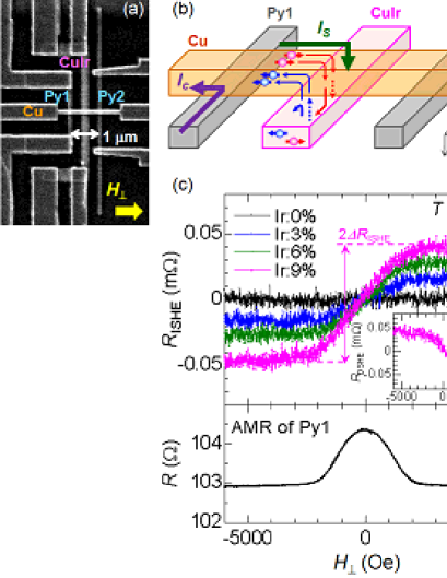
Samples have been fabricated on a thermally oxidized silicon substrate using electron beam lithography on polymethyl-methacrylate resist and a subsequent lift-off process. We have used a lateral spin valve structure which consists of two Permalloy (Ni81Fe19; hereafter Py) wires (30 nm thick and 100 nm wide) and a CuIr middle wire (20 nm thick and 250 nm wide) bridged by a Cu wire (100 nm thick and 100 nm wide), as shown in Fig. 1(a). In this work, the distance between the two Py wires () is fixed to 1 m and the CuIr wire is placed just in the middle of the two Py wires. To induce a difference between the switching fields of the two Py wires, one of them [Py1 in Fig. 1(a)] has two large pads at the edges. The Py wires were grown by electron beam evaporation, while the middle CuIr wires with different Ir concentrations (0%, 1%, 3%, 6%, 9%, and 12%) were deposited by magnetron sputtering. The Cu bridge was fabricated by a Joule heating evaporator using a 99.9999% purity source. Prior to Cu evaporation a careful Ar ion beam etching (600 V beam voltage) was carried out for 1 min in order to clean the surfaces of Py and CuIr wires and to obtain highly transparent Ohmic contacts. Transport measurements were performed using a standard ac lock-in technique and a 4He flow cryostat. The magnetic field is applied along the hard and easy axes of Py for ISHE and nonlocal spin valve (NLSV) measurements, respectively. For each Ir concentration, at least three different samples from the same batch have been measured to check the reproducibility.
First we discuss the ISHE results for CuIr with different Ir concentrations. The measurement circuit is depicted in Fig. 1(b). When the electric current flows from Py1 to the left side of the Cu wire, the resulting spin accumulation induces a pure spin current on the right side of the Cu wire. As we discuss in the next paragraph, a major part of the pure spin current is absorbed in the CuIr middle wire below the Cu wire since the spin diffusion length of CuIr ( nm) is much smaller than that of Cu. The deflection in the same direction of the opposite spin-up and down vertical currents by skew scattering on the Ir impurities generates the ISHE signal. The ISHE resistance (equal to the ISHE voltage divided by the charge current ), is plotted in Fig. 1(c) as a function of the magnetic field applied perpendicularly to the Py wires. increases linearly with the magnetic field up to 2000 Oe and then flattens off at the saturation of the magnetization of Py1 [see the anisotropic magnetoresistance (AMR) curve of Py1 in the bottom panel of Fig. 1(c)]. It can also be seen in Fig. 1(c) that increases with increasing Ir. The inversion of the probe configuration [i.e., , in Fig. 1(a)] enables one to measure the DSHE as previously reported kimura_prl_07 ; vila_prl_07 . We could confirm that the SH resistance due to the DSHE is exactly the same as [see the inset of Fig. 1(c)]. This verifies the Onsager reciprocal relation in our system.
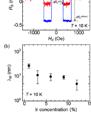
In order to estimate the spin diffusion length of CuIr and to use it in the evaluation of the spin current absorbed into the CuIr wire, we have measured the NLSV signal of our device. Note that in this case the magnetic field is applied along the easy axis of the two Py wires. As can be seen in Fig. 2(a), by inserting the CuIr middle wire, the spin accumulation signal () is reduced to where is the spin accumulation signal without middle wires. This indicates that most of the pure spin current injected from Py1 is absorbed in the CuIr wire. From the one-dimensional spin diffusion model takahashi_prb_03 , the normalized spin signal can be expressed as follows;
| (1) |
where and are the spin resistances of Cu and CuIr middle wire, respectively. The spin resistance of material “X” is defined as , where , , and are respectively the electrical resistivity, the spin diffusion length, the spin polarization, and the effective cross sectional area involved in the equations of the one-dimensional spin diffusion model note_polarization . As reported previously kimura_prl_08 , we can determine , , and by measuring the NLSV signal without middle wire as a function of . In the present study, m, nm, and at K. Thus, we can extract the spin diffusion length of the CuIr middle wire from Eq. (1). As can be seen in Fig. 2(b), drastically decreases with increasing the Ir atom.
We then calculate as follows maekawa ; takahashi_review_08 :
| (2) |
where is the effective spin current injected (vertically for ) into the CuIr wire and generating the ISHE, is the width of CuIr wire and is a correction factor taking into account the fact that the horizontal current driven by the ISHE voltage balancing the SO deflections is partially shunted by the Cu wire above the CuIr/Cu interface. The correction factor is derived from additional measurements of the resistance of the CuIr wire with and without the interface with Cu and is found to be 0.360.08 for all the samples (see supplemental material supplemental ); for the DSHE the same factor accounts for the shunting of the current through Cu. is defined as the difference between at saturation field (above 2000 Oe) and at zero field [see Fig. 1 (c)]. In our case is generally smaller than the thickness of the CuIr middle wire. The spin current injected from the interface with Cu decreases in the CuIr wire, exponentially in the limit , linearly down to zero at the bottom of CuIr for , the general expression of for values of (20 nm) and [ nm in Fig. 2(b)] much smaller than (100 nm) being morota ;
| (3) | |||||
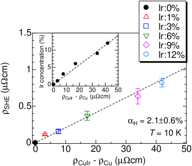
By using Eqs. (2) and (3) we can derive the SH resistivity from . In Fig. 3 we plot of CuIr as a function of the resistivity induced by the Ir impurities, i.e. . It nicely follows a simple linear dependence up to Ir concentration of 12%. This clearly shows that the dominant mechanism of the extrinsic SHE induced by the Ir impurities is the skew scattering. The SH angle characteristic of this skew scattering, , is %. In the previous measurements of the ISHE due to the skew scattering induced by Ir impurities in Cu after spin-polarization of the current by dilute Mn impurities (Mn impurities alone not contributing to the Hall effect), was 2.6%, which is quantitatively consistent with our result fert_1981 .
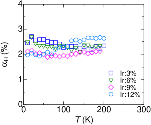
As shown in Fig. 4, the SH angle changes only weakly as a function of temperature. This is an additional proof for the mechanism of skew scattering by impurities since the contributions from intrinsic SHE or impurity scattering with side jump would be affected by the temperature dependence of the total resistivity. Finally, let us mention some results we obtained on the SH resistivity of AgIr. In this case, the estimated SH angle is definitely smaller, 0.6%. This large reduction is probably due to the very small solubility of Ir in Ag karakaya .
In conclusion, we have measured the SH resistivity of the SHE induced by Ir impurities in Cu. The SH resistivity is approximately proportional to the impurity-induced resistivity and practically temperature independent, which allows us to ascribe it to skew scattering on the Ir impurities. For the SH angle, characteristic parameter of the transformation of charge into spin current, we find 2.1%, which is quantitatively consistent with the value derived in previous experiments on CuIr, 2.6% fert_1981 . Such values of the SH angle are larger than those obtained with pure metals saitoh_apl_06 ; kimura_prl_07 ; vila_prl_07 ; hoffmann_prl_10 ; morota and confirm that scattering by impurities is a very promising way to obtain large SH angles, as it is predicted by several recent skew scattering calculations papers mertig ; gu ; fert_review . Fert and Levy fert_review have calculated the contributions from both skew scattering and scattering with side jump on impurities in Cu. For Ir impurities, they predict predominant skew scattering effects in the concentration range of our experiments, in agreement with our results. However, for other types of impurities (Os, Ta) in Cu, they find that the side-jump contribution to the SH angle can be definitely larger, that is a few percent for concentrations in the 1% range and therefore above 10% for concentrations in the 10% range fert_review . Alloys combining side-jump and skew scattering effects in such a concentration range are promising to obtain a large SH angle and an efficient transformation of charge current into spin current in devices without magnetic components.
We acknowledge helpful discussions with H. Jaffres, S. Takahashi, and S. Maekawa, and numerical simulations performed by P. Metaxas and P. Bortoloti. We would also like to thank Y. Iye and S. Katsumoto for the use of the lithography facilities. This work was supported by KAKENHI and a Grant-in-Aid for Scientific Research in Priority Area from MEXT.
References
- (1) See, for example, S. Maekawa, Concepts in Spin Electronics (Oxford University Press, Oxford, 2006).
- (2) M. I. Dyakonov and V. I. Perel, Phys. Lett. A 35, 459 (1971).
- (3) J. E. Hirsch, Phy. Rev. Lett. 83, 1834 (1999).
- (4) S. Zhang, Phy. Rev. Lett. 85, 393 (2000).
- (5) Y. K. Kato et al., Science 306, 1910 (2004).
- (6) E. Saitoh et al., Appl. Phys. Lett. 88, 182509 (2006).
- (7) T. Kimura et al., Phys. Rev. Lett. 98, 156601 (2007).
- (8) L. Vila, T. Kimura, and Y. Otani, Phys. Rev. Lett. 99, 226604 (2007).
- (9) O. Mosendz et al., Phys. Rev. Lett. 104, 046601 (2010); Phys. Rev. B 82 214403 (2010).
- (10) M. Morota et al., arXiv:1008.0158.
- (11) T. Seki et al., Nature Mater. 7, 125 (2008).
- (12) G. Mihajlović et al., Phys. Rev. Lett. 103, 166601 (2009).
- (13) H. Kontani et al., J. Phys. Soc. Jpn. 76, 103702 (2007).
- (14) T. Tanaka et al., Phys. Rev. B 77, 165117 (2008).
- (15) H. Kontani et al., Phys. Rev. Lett. 102, 016601 (2009).
- (16) M. Gradhand et al., Phys. Rev. Lett. 104, 186403 (2010).
- (17) B. Gu et al., Phys. Rev. Lett. 105, 216401 (2010).
- (18) A. Fert and P. M. Levy, arXiv:1012.3657.
- (19) J. Smit, Physica (Amsterdam) 24, 39 (1958).
- (20) L. Berger, Phys. Rev. B 2, 4559 (1970).
- (21) A. Fert et al., J. Magn. Magn. Mat. 24, 231 (1981).
- (22) S. O. Valenzuela and M. Tinkham, Nature(London) 442, 176 (2006).
- (23) S. Takahashi and S. Maekawa, Phys. Rev. B 67, 052409 (2003).
- (24) and are zero since Cu and CuIr are nonmagnetic metals. for , for , and for . The product (, ) characterizes the effective volume of spin relaxation in N (F, M).
- (25) T. Kimura, T. Sato, and Y. Otani, Phys. Rev. Lett. 100, 066602 (2008).
- (26) S. Takahashi and S. Maekawa, Sci. Technol. Adv. Mater. 9, 014105 (2008).
- (27) See supplemental material for detailed information about how to estimate experimentally.
- (28) I. Karakaya and W. T. Thompson, Bull. Alloy Phase Diagrams 7, 359 (1986).