Aligned Interference Neutralization
and the Degrees of Freedom of the 222 User Interference Channel with Instantaneous Relay

Namyoon Lee, Syed A. Jafar

Samsung Electronics CO., LTD, Suwon, Korea
University of California Irvine
E-mail : namyoon.lee@gmail.com, syed@uci.edu
Abstract

It is well known that the classical 2 user Gaussian interference channel has only 1 degree of freedom (DoF), which can be achieved by orthogonal time division among the 2 users. It is also known that the use of conventional relays, which introduce a processing delay of at least one symbol duration relative to the direct paths between sources and destinations, does not increase the DoF of the 2 user interference channel. The use of instantaneous relays (relays-without-delay) has been explored for the single user point-to-point setting and it is known that such a relay, even with memoryless forwarding at the relay, can achieve a higher capacity than conventional relays. In this work, we show that the 2 user interference channel with an instantaneous relay, achieves 3232\frac{3}{2} DoF. Thus, an instantaneous relay increases not only the capacity but also the DoF of the 2 user interference channel. The achievable scheme is inspired by the aligned interference neutralization scheme recently proposed for the 2×2×22222\times 2\times 2 interference channel. Remarkably the DoF gain is achieved with memoryless relays, i.e., with relays that have no memory of past received symbols.

1 Introduction

Due to the broadcast nature of the wireless medium, simultaneously transmitted signals from multiple source nodes cause interference to each other. The interference gives rise to competition between different information flows, but it can also be exploited for cooperation between them. Understanding the complex interplay between cooperation and competition is the key to understanding the capacity limits of wireless networks. In spite of an abundance of literature studying cooperative interference networks, the understanding of this topic — even at a coarse degrees-of-freedom (DoF) level — is far from mature, as evident from any sampling of recent works on DoF characterizations of cooperative interference networks that have produced surprising insights. Continuing in the same spirit, in this work we seek to illuminate a few interesting and fundamental aspects of the interplay between cooperation and competition, from a DoF perspective. The setting we wish to explore is the 2 user interference channel with an instantaneous relay.

Competition for DoF in the 2 User Interference Channel

From a DoF perspective, the two user interference channel represents competition for resources in the strongest sense — whatever DoF one user is able to achieve, comes at the cost of an equal amount of the other user’s DoF. This is because it is well known that the 2 user interference channel has only 1 DoF, which can be achieved by any orthogonal time division policy between the two users.

The Use of Relays in the Interference Channel

To alleviate the competition between the two users, the use of relay nodes has been considered. Indeed, there are several results that show increased rates in the form of SNR gains from employing a relay in an interference channel [1, 2, 3, 4, 5]. DoF gains are achieved with the use of relays when source and destination nodes are not directly connected, e.g., in layered relay networks. Reference [6] provides a characterization of the DoF of the multihop 2 user interference channel with layered relays. However, if direct channel coefficients between source and destination nodes are non-zero, then from a DoF perspective, it has been shown that the use of relays does not contribute any DoF gain for the 2 user interference channel [7], regardless of the number of relay nodes. Remarkably, this is true even if the relay nodes are equipped with multiple antennas111Exceptions include cases where relays are cognitive, i.e., they have prior knowledge of source messages [8], or when the power constraints at the relay nodes are orders of magnitude higher than the source nodes [9]..

From Conventional Relay to Instantaneous Relay

Since conventional relays are shown not to increase the DoF of a two user interference channel, we explore another form of relaying, introduced by El Gamal and Hassanpour [10], known as instantaneous relaying (relay-without-delay). Unlike the classical relay whose transmitted signal is a function of only past observations, the transmitted signal from an instantaneous relay, is allowed to depend on both past and current received signals. Furthermore, a memoryless instantaneous relay is a constrained form of an instantaneous relay, where the transmitted signal is allowed to depend only on the current received signal. Clearly, a memoryless instantaneous relay is a simpler but less powerful relay than a general instantaneous relay, which in turn is more powerful than a conventional relay. Interestingly, no order relationship necessarily exists between conventional relays and instantaneous memoryless relay. Because the latter has the benefit of being able to react to the current received signal but the handicap of having no memory of past received signals, it may or may not be better than a conventional relay in general. For the single user setting, since the memoryless nature of the relay does not allow decode and forward processing, it is clear that such a relay channel will have a smaller capacity than a conventional relay in those settings where decode and forward processing is needed, e.g., when there is no direct path between the source and destination. On the other hand, El Gamal and Hassanpour [10] show that the memoryless instantaneous relay channel can have a higher capacity than a conventional relay. While the result is surprising, the capacity gains are modest and limited to SNR gains. However, as we show in this paper, the use of a memoryless instantaneous relay in a 2 user interference channel has a very significant impact as it increases the DoF by at least 50% (from 1 to 1.5) for almost all channel realizations.

Practical Motivation for Interference Channel with Instantaneous Relay

Refer to caption
Figure 1: Practical Motivation for Instantaneous Relay

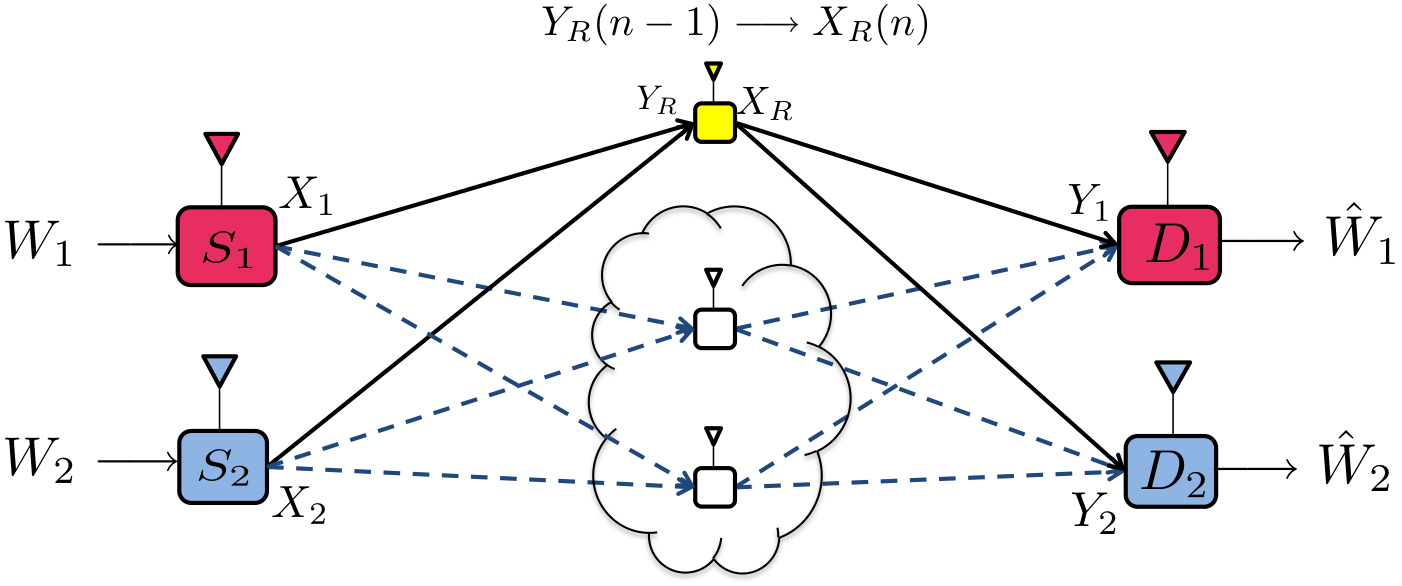
Practical scenarios that can be modeled by the instantaneous relay setting can arise in a number of ways. Here we outline one motivating example, shown in Fig. 1. Consider a two user interference channel where communication takes place over two hops with the use of conventional relays. There are no direct links between sources and destinations, presumably because of the excessive propagation path loss, that necessitates the use of relay nodes. It is well known that in such a network, one can completely eliminate all interference to achieve the min-cut bound DoF=2𝐷𝑜𝐹2DoF=2 with 333 or more relay nodes, provided we have global channel knowledge and intelligent relay nodes. However, both global channel knowledge and intelligence at all relays are not easily available in practice. A practical alternative is to choose a subset of relay nodes which are intelligent and let these relay nodes acquire the channel knowledge they need, while the remaining relay nodes remain dumb, e.g., by simply amplifying and forwarding their received signals with no knowledge of channel conditions, nor any ability to tailor their transmissions to the channel conditions. Such a setting is shown in Fig. 1, where the highlighted relay node in yellow is the intelligent relay that acquires the channel knowledge that it needs. All other relay nodes (indicated in white) remain oblivious of the channel states and simply amplify and forward their signals with a fixed amplification factor that does not depend on channel state. Thus, the channels between sources and destinations that pass through the dumb relays can be represented as an effective channel matrix and equivalently viewed as a direct channel between the sources and destinations. It is this effective channel that is learnt by the destination nodes, in addition to the channels seen from the intelligent relay node.

Refer to caption
Figure 2: Interference Channel with Memoryless Instantaneous Relay

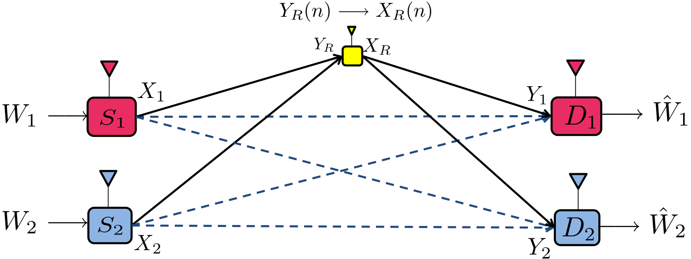
These practical assumptions lead us to the model shown in Fig. 2, where the dumb relays are not explicitly shown and instead only the effective channel is retained (shown with dashed lines). Since all signals arrive at the destinations with equal delay of two hops, and the dumb relays are ignored, we correspondingly shift the time reference at the intelligent relay, so that it is modeled as an instantaneous relay. The assumption of memoryless instantaneous relay is not essential to this work, since we focus only on achievable schemes, which will remain achievable even if the relay is allowed to have memory. Rather it is just a feature of our achievable scheme that the relays do not need to use any memory of past received symbols. Finally, we assume that the relays are full-duplex in our channel model Fig. 2, which could again be justified as a consequence of an underlying protocol in the practical setting of Fig. 1 whereby the relays transmit and receive in two orthogonal phases. Thus, the channel model of the interference channel with instantaneous relay arises naturally from a two-hop interference channel with several dumb relay nodes and one intelligent relay node.

Henceforth, we will use only the channel model illustrated in Fig. 2, i.e., with the assumptions of instantaneous, full-duplex relays. The justification for these assumptions will not be repeated.

Contribution

The main contribution of this paper is to show that 3232\frac{3}{2} DoF is achievable for the interference channel with the instantaneous relay. This is remarkable in light of the result that conventional relays do not increase DoF beyond 1. Thus, there is a very significant DoF gain from the relay’s ability to instantly forward the received signal from the sources to the destinations. Also surprising is that this remarkable DoF gain is achievable without any memory at the relay. The DoF gain extends to the setting where every node is equipped with M1𝑀1M\geq 1 antennas. In this case, 3M23𝑀2\frac{3M}{2} DoF are achieved The result is also interesting because of the non-trivial nature of the achievable scheme, which is inspired by the idea of aligned interference neutralization recently introduced by Gou et. al. in [11].

For the multiple antenna case, M>1𝑀1M>1, we construct a linear beamforming scheme to achieve aligned interference neutralization. The two sources and the relay cooperatively construct beamforming vectors so that the interference signals coming from different paths are eliminated at the unintended destination. Further, we will also describe a simple modification of the beamforming scheme that can achieve SNR gain for desired data signals while maintaining 3M23𝑀2\frac{3M}{2} DoF. The modified scheme designs the beamforming vectors in such a way that not only are the interference signals coming from different paths eliminated at the unintended destination, but also the desired signals coming from different paths are coherently combined at the desired destinations.

For single antenna case, i.e., M=1𝑀1M=1, we translate the proposed linear beamforming scheme into the rational dimensions framework introduced in [12] and [13]. Using this framework, we will also show that 3232\frac{3}{2} DoF are achieved for the interference channel with the instantaneous relay when the channel coefficient values remain fixed.

The rest of the paper is organized as follows. In Section II, the system model is described and the key concept of proposed scheme is precisely explained using a simple example in Section III. In Section IV we derive the lower bound of DoF for the interference channel with the instantaneous relay, assuming all nodes have multiple antennas. Using the rational dimension framework, we also derive the lower bound of DoF for a single antenna system in Section V. The paper is concluded in Section VI with discussions for the role of a relay in the interference channel.

2 System model

As shown in Fig. 2 our channel model consists of two sources, two destinations, and an intermediate relay. In this channel, source Sisubscript𝑆𝑖S_{i}, i=1,2𝑖12i=1,2, wishes to send an independent message W[i]superscript𝑊delimited-[]𝑖W^{[i]} to its respective destination Disubscript𝐷𝑖D_{i}. Global channel knowledge is assumed at all 5 nodes, with the notable exception that the source nodes need not learn the channel coefficients for the direct channels to the destination nodes (i.e., the dashed links in Fig. 2, i.e., the source nodes only need to learn their channels to the relay node. The relay operates in full-duplex mode and it instantaneously forwards the currently received data symbols from the sources to the destinations. For a multiple antenna system, input-output relationships of the channel are given by

𝐲[R]superscript𝐲delimited-[]𝑅\displaystyle{\bf y}^{[R]}\!\!\!\!\! =\displaystyle= i=12𝐇[R,i]𝐱[i]+𝐧[R]superscriptsubscript𝑖12superscript𝐇𝑅𝑖superscript𝐱delimited-[]𝑖superscript𝐧delimited-[]𝑅\displaystyle\!\!\!\!\!\sum_{i=1}^{2}{\bf H}^{[R,i]}{\bf x}^{[i]}\!+\!{\bf n}^{[R]}
𝐲[1]superscript𝐲delimited-[]1\displaystyle{\bf y}^{[1]}\!\!\!\!\! =\displaystyle= i=12𝐇[1,i]𝐱[i]+𝐇[1,R]𝐱[R]+𝐧[1]superscriptsubscript𝑖12superscript𝐇1𝑖superscript𝐱delimited-[]𝑖superscript𝐇1𝑅superscript𝐱delimited-[]𝑅superscript𝐧delimited-[]1\displaystyle\!\!\!\!\!\sum_{i=1}^{2}{\bf H}^{[1,i]}{\bf x}^{[i]}+{\bf H}^{[1,R]}{\bf x}^{[R]}\!+\!{\bf n}^{[1]}
𝐲[2]superscript𝐲delimited-[]2\displaystyle{\bf y}^{[2]}\!\!\!\!\! =\displaystyle= i=12𝐇[2,i]𝐱[i]+𝐇[2,R]𝐱[R]+𝐧[2],superscriptsubscript𝑖12superscript𝐇2𝑖superscript𝐱delimited-[]𝑖superscript𝐇2𝑅superscript𝐱delimited-[]𝑅superscript𝐧delimited-[]2\displaystyle\!\!\!\!\!\sum_{i=1}^{2}{\bf H}^{[2,i]}{\bf x}^{[i]}+{\bf H}^{[2,R]}{\bf x}^{[R]}\!+\!{\bf n}^{[2]}, (1)

where 𝐲[j]superscript𝐲delimited-[]𝑗{\bf y}^{[j]}, j{1,2,R}𝑗12𝑅j\in\{1,2,R\} denotes the channel output vector with size of M×1𝑀1M\times 1 at Receiver j𝑗j, 𝐇[j,i]superscript𝐇𝑗𝑖{\bf H}^{[j,i]} is the M×M𝑀𝑀M\times M channel matrix from the sender i𝑖i to the receiver j𝑗j where i,j{1,2,R}𝑖𝑗12𝑅i,j\in\{1,2,R\}, and 𝐧[j]superscript𝐧delimited-[]𝑗{\bf n}^{[j]} j{1,2,R}𝑗12𝑅j\in\{1,2,R\} represents a noise signal vector with size of M×1𝑀1M\times 1 at the destination j𝑗j whose elements are random variables drawn from an independent and identically distributed (i.i.d.) zero mean complex Gaussian distribution with unit variance, i.e., 𝒩𝒞(0,1)𝒩𝒞01\mathcal{NC}(0,1). In addition, we assume that all elements of each channel matrix are drawn from 𝒩𝒞(0,1)𝒩𝒞01\mathcal{NC}(0,1). The average power constraint of the transmitted signals by the sender i𝑖i, 𝐱[i]superscript𝐱delimited-[]𝑖{\bf x}^{[i]}, is given by

𝔼[Tr(𝐱[i]𝐱[i]H)]P,i{1,2,R}.formulae-sequence𝔼delimited-[]Trsuperscript𝐱delimited-[]𝑖superscriptsuperscript𝐱delimited-[]𝑖𝐻𝑃𝑖12𝑅\displaystyle\mathbb{E}\left[\textmd{Tr}\left({\bf x}^{[i]}{{\bf x}^{[i]}}^{H}\right)\right]\leq P,\quad i\in\{1,2,R\}. (2)

For codewords spanning n𝑛n channel uses, a rate R[i](P)=log|W[i](P)|nsuperscript𝑅delimited-[]𝑖𝑃superscript𝑊delimited-[]𝑖𝑃𝑛R^{[i]}(P)=\frac{\log|W^{[i]}(P)|}{n} is achievable if the probability of error for the message W[i]superscript𝑊delimited-[]𝑖W^{[i]} approaches zero as n𝑛n\rightarrow\infty. The DoF characterizing the high SNR behavior of the achievable rate is defined as

d[i]=limPR[i](P)log(P),i{1,2}.formulae-sequencesuperscript𝑑delimited-[]𝑖subscript𝑃superscript𝑅delimited-[]𝑖𝑃𝑃𝑖12\displaystyle d^{[i]}=\lim_{P\rightarrow\infty}\frac{R^{[i]}(P)}{\log(P)},\quad i\in\{1,2\}. (3)

3 Proposed scheme

For ease of exposition, we first explain our proposed scheme with a simple example when M=4𝑀4M=4.

Refer to caption
Figure 3: The proposed scheme for the interference channel with the instantaneous relay when M=4𝑀4M=4.

3.1 Transmission scheme at two source nodes
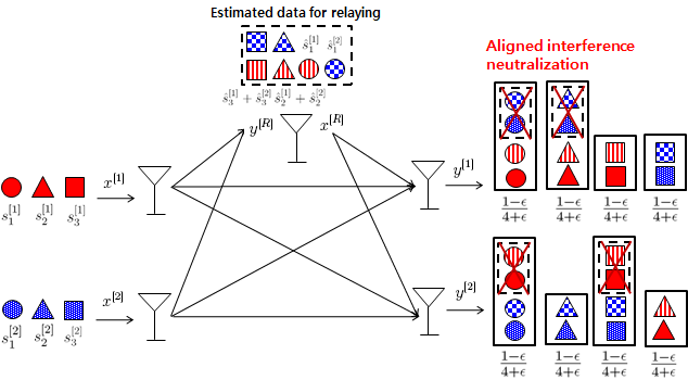
As shown in Fig. 3, Source Sisubscript𝑆𝑖S_{i} wishes to deliver three independent data symbols s1[i]subscriptsuperscript𝑠delimited-[]𝑖1s^{[i]}_{1}, s2[i]subscriptsuperscript𝑠delimited-[]𝑖2s^{[i]}_{2}, and s3[i]subscriptsuperscript𝑠delimited-[]𝑖3s^{[i]}_{3} by using linear beamforming vectors 𝐯1[i]subscriptsuperscript𝐯delimited-[]𝑖1{\bf v}^{[i]}_{1}, 𝐯2[i]subscriptsuperscript𝐯delimited-[]𝑖2{\bf v}^{[i]}_{2}, and 𝐯3[i]subscriptsuperscript𝐯delimited-[]𝑖3{\bf v}^{[i]}_{3} to the corresponding destination Disubscript𝐷𝑖D_{i}, where i{1,2}𝑖12i\in\{1,2\}. Since each source transmits three independent data symbols, each destination and the receiver of the relay node see six competing flows of information. If each receiver has M6𝑀6M\geq 6 antennas, it is easily seen that without the help of the relay, each destination node can get three desired data symbols by removing the interfering symbols. However, when we only have M=4𝑀4M=4 antennas, the two destinations cannot by default resolve the 3 desired symbols from the 3 interfering symbols when confined to an overall four dimensional space. To do this, the two source nodes cooperatively design transmit beamforming vectors so that the relay sees the following four data symbols in a four dimensional space: s1[1]subscriptsuperscript𝑠delimited-[]11{s}^{[1]}_{1}, s1[2]subscriptsuperscript𝑠delimited-[]21{s}^{[2]}_{1}, L[R](s2[1],s2[2])superscript𝐿delimited-[]𝑅subscriptsuperscript𝑠delimited-[]12subscriptsuperscript𝑠delimited-[]22L^{[R]}\left({s}^{[1]}_{2},{s}^{[2]}_{2}\right), and L[R](s3[1],s3[2])superscript𝐿delimited-[]𝑅subscriptsuperscript𝑠delimited-[]13subscriptsuperscript𝑠delimited-[]23L^{[R]}\left({s}^{[1]}_{3},{s}^{[2]}_{3}\right) where L[j](a,b)superscript𝐿delimited-[]𝑗𝑎𝑏L^{[j]}(a,b) denotes a linear combination of a𝑎a and b𝑏b at the j𝑗j-th receiver. To achieves these goals, the beamforming vectors of two source nodes are picked as

span(𝐇[R,1]𝐯2[1])spansuperscript𝐇𝑅1subscriptsuperscript𝐯delimited-[]12\displaystyle\textrm{span}\left({\bf H}^{[R,1]}{\bf v}^{[1]}_{2}\right) =\displaystyle= span(𝐇[R,2]𝐯2[2])spansuperscript𝐇𝑅2subscriptsuperscript𝐯delimited-[]22\displaystyle\textrm{span}\left({\bf H}^{[R,2]}{\bf v}^{[2]}_{2}\right)
span(𝐇[R,1]𝐯3[1])spansuperscript𝐇𝑅1subscriptsuperscript𝐯delimited-[]13\displaystyle\textrm{span}\left({\bf H}^{[R,1]}{\bf v}^{[1]}_{3}\right) =\displaystyle= span(𝐇[R,2]𝐯3[2]),spansuperscript𝐇𝑅2subscriptsuperscript𝐯delimited-[]23\displaystyle\textrm{span}\left({\bf H}^{[R,2]}{\bf v}^{[2]}_{3}\right), (4)

where span(𝐀)𝐀\left({\bf A}\right) stands for the vector space spanned by the column vectors of matrix 𝐀𝐀{\bf A}. Note that if the source nodes know only their own channels to the destination node, then it is also possible to achieve the same alignments, by having the relay choose offline the dimensions along which the alignments should occur. Since this choice is made offline, it is known to the source nodes, who can then design their beams to reach the relay in the correct dimension, without needing to learn the other source’s channel to the relay node.

3.2 Relaying strategy

Note that each destination sees six independent data symbols from two sources nodes while it has four antennas. Therefore, the relay transmission strategy is to forward a signal so that it simultaneously removes at least two interference data symbols at each destination. We know that the relay estimates four data symbols from two source nodes, which are s1[1]subscriptsuperscript𝑠delimited-[]11s^{[1]}_{1}, s1[2]subscriptsuperscript𝑠delimited-[]21{s}^{[2]}_{1}, L[R](s2[1],s2[2])superscript𝐿delimited-[]𝑅subscriptsuperscript𝑠delimited-[]12subscriptsuperscript𝑠delimited-[]22L^{[R]}\left({s}^{[1]}_{2},{s}^{[2]}_{2}\right), and L[R](s3[1],s3[2])superscript𝐿delimited-[]𝑅subscriptsuperscript𝑠delimited-[]13subscriptsuperscript𝑠delimited-[]23L^{[R]}\left({s}^{[1]}_{3},{s}^{[2]}_{3}\right). Using the estimated data symbols, we first generate transmit data symbols sent by the relay, which are

s1[R]subscriptsuperscript𝑠delimited-[]𝑅1\displaystyle{s}^{[R]}_{1} =\displaystyle= s1[1],s2[R]=s1[2],subscriptsuperscript𝑠delimited-[]11subscriptsuperscript𝑠delimited-[]𝑅2subscriptsuperscript𝑠delimited-[]21\displaystyle{s}^{[1]}_{1},\quad\quad\quad\quad\quad\quad{s}^{[R]}_{2}={s}^{[2]}_{1},
s3[R]subscriptsuperscript𝑠delimited-[]𝑅3\displaystyle{s}^{[R]}_{3} =\displaystyle= L[R](s2[1],s2[2]),s4[R]=L[R](s3[1],s3[2]).superscript𝐿delimited-[]𝑅subscriptsuperscript𝑠delimited-[]12subscriptsuperscript𝑠delimited-[]22subscriptsuperscript𝑠delimited-[]𝑅4superscript𝐿delimited-[]𝑅subscriptsuperscript𝑠delimited-[]13subscriptsuperscript𝑠delimited-[]23\displaystyle L^{[R]}\left({s}^{[1]}_{2},{s}^{[2]}_{2}\right),\quad{s}^{[R]}_{4}=L^{[R]}\left({s}^{[1]}_{3},{s}^{[2]}_{3}\right). (5)

As a next step, we also design the relay beamforming vectors 𝐯i[R]subscriptsuperscript𝐯delimited-[]𝑅𝑖{\bf v}^{[R]}_{i} for carrying si[R]subscriptsuperscript𝑠delimited-[]𝑅𝑖{s}^{[R]}_{i}, i{1,2,3,4}𝑖1234i\in\{1,2,3,4\}. The proposed relay beamforming strategy is as follows:

  • Relay picks 𝐯1[R]subscriptsuperscript𝐯delimited-[]𝑅1{\bf v}^{[R]}_{1} to cancel s1[1]subscriptsuperscript𝑠delimited-[]11{s}^{[1]}_{1} at Destination 2.

  • Relay picks 𝐯2[R]subscriptsuperscript𝐯delimited-[]𝑅2{\bf v}^{[R]}_{2} to cancel s1[2]subscriptsuperscript𝑠delimited-[]21{s}^{[2]}_{1} at Destination 1.

  • Relay picks 𝐯3[R]subscriptsuperscript𝐯delimited-[]𝑅3{\bf v}^{[R]}_{3} to cancel s2[2]subscriptsuperscript𝑠delimited-[]22{s}^{[2]}_{2} at Destination 1.

  • Relay picks 𝐯4[R]subscriptsuperscript𝐯delimited-[]𝑅4{\bf v}^{[R]}_{4} to cancel s3[1]subscriptsuperscript𝑠delimited-[]13{s}^{[1]}_{3} at Destination 2.

To accomplish this goal, we choose the relay beamforming vectors 𝐯i[R]subscriptsuperscript𝐯delimited-[]𝑅𝑖{\bf v}^{[R]}_{i} as

𝐇[2,R]𝐯1[R]superscript𝐇2𝑅subscriptsuperscript𝐯delimited-[]𝑅1\displaystyle{\bf H}^{[2,R]}{\bf v}^{[R]}_{1} =\displaystyle= 𝐇[2,1]𝐯1[1],𝐇[1,R]𝐯2[R]=𝐇[1,2]𝐯1[2]superscript𝐇21subscriptsuperscript𝐯delimited-[]11superscript𝐇1𝑅subscriptsuperscript𝐯delimited-[]𝑅2superscript𝐇12subscriptsuperscript𝐯delimited-[]21\displaystyle-{\bf H}^{[2,1]}{\bf v}^{[1]}_{1},\quad{\bf H}^{[1,R]}{\bf v}^{[R]}_{2}=-{\bf H}^{[1,2]}{\bf v}^{[2]}_{1}
𝐇[1,R]𝐯3[R]superscript𝐇1𝑅subscriptsuperscript𝐯delimited-[]𝑅3\displaystyle{\bf H}^{[1,R]}{\bf v}^{[R]}_{3} =\displaystyle= 𝐇[1,2]𝐯2[2],𝐇[2,R]𝐯4[R]=𝐇[2,1]𝐯3[1].superscript𝐇12subscriptsuperscript𝐯delimited-[]22superscript𝐇2𝑅subscriptsuperscript𝐯delimited-[]𝑅4superscript𝐇21subscriptsuperscript𝐯delimited-[]13\displaystyle-{\bf H}^{[1,2]}{\bf v}^{[2]}_{2},\quad{\bf H}^{[2,R]}{\bf v}^{[R]}_{4}=-{\bf H}^{[2,1]}{\bf v}^{[1]}_{3}. (6)

3.3 Decoding at destinations

Now we need to check whether each destination can decode three desired data symbols. From the relay transmission, two of the undesired signals are neutralized at each destination, leaving only four signals which can be resolved in a four dimensional space. The remaining data symbols at each destination are

  • Destination 1 observes four signals: s1[1]subscriptsuperscript𝑠delimited-[]11{s}^{[1]}_{1}, s2[1]subscriptsuperscript𝑠delimited-[]12{s}^{[1]}_{2}, s3[1]subscriptsuperscript𝑠delimited-[]13{s}^{[1]}_{3}, and s3[2]subscriptsuperscript𝑠delimited-[]23{s}^{[2]}_{3}.

  • Destination 2 observes four signals: s1[2]subscriptsuperscript𝑠delimited-[]21{s}^{[2]}_{1}, s2[2]subscriptsuperscript𝑠delimited-[]22{s}^{[2]}_{2}, s3[2]subscriptsuperscript𝑠delimited-[]23{s}^{[2]}_{3}, and s2[1]subscriptsuperscript𝑠delimited-[]12{s}^{[1]}_{2}.

As a result, each destination can decode three independent data symbols and thus 6 DoF are achieved when M=4𝑀4M=4. This is interesting because it is higher than the 4 DoF that can be achieved for the two-user MIMO interference channel without involving the relay node [15].

4 Achievable DoF for Multiple Antenna Systems

The following theorem is the main result of this paper.

Theorem 1: In a complex MIMO Gaussian interference channel with an instantaneous relay, 3M23𝑀2\frac{3M}{2} DoF is achievable for M>1𝑀1M>1.

Proof:) The achievability proof is shown by aligned interference neutralization with interference-forward relaying scheme. Here, we will show (d[1],d[2])=(3M4,3M4)superscript𝑑delimited-[]1superscript𝑑delimited-[]23𝑀43𝑀4(d^{[1]},d^{[2]})=(\frac{3M}{4},\frac{3M}{4}) when M𝑀M is multiple of 4 for simplicity. For arbitrary M𝑀M, we can straightforwardly show that the same DoF can be achieved using 4 time symbol extension technique as shown in the both the MIMO X channel [16] and the MIMO Y channel [17]. However, note that the symbol extension based achievability schemes, needed when M𝑀M is not a multiple of 444, do require memory in the relay processing, over 4 consecutive symbols. This requirement can be reduced by exploiting asymmetric complex signaling, in which case only two symbol extensions would suffice.

Sources

Let us start by splitting each transmit message at source nodes into three submessages, i,e., W[1]={W1[1],W2[1],W3[1]}superscript𝑊delimited-[]1subscriptsuperscript𝑊delimited-[]11subscriptsuperscript𝑊delimited-[]12subscriptsuperscript𝑊delimited-[]13W^{[1]}=\{W^{[1]}_{1},W^{[1]}_{2},W^{[1]}_{3}\} and W[2]={W1[2],W2[2],W3[2]}superscript𝑊delimited-[]2subscriptsuperscript𝑊delimited-[]21subscriptsuperscript𝑊delimited-[]22subscriptsuperscript𝑊delimited-[]23W^{[2]}=\{W^{[2]}_{1},W^{[2]}_{2},W^{[2]}_{3}\}. Each submessage Wj[i]subscriptsuperscript𝑊delimited-[]𝑖𝑗W^{[i]}_{j} is encoded into r=M4𝑟𝑀4r=\frac{M}{4} transmit symbols, i.e., sj,1[i],sj,2[i],,sj,r[i]subscriptsuperscript𝑠delimited-[]𝑖𝑗1subscriptsuperscript𝑠delimited-[]𝑖𝑗2subscriptsuperscript𝑠delimited-[]𝑖𝑗𝑟s^{[i]}_{j,1},s^{[i]}_{j,2},\ldots,s^{[i]}_{j,r}, using a Gaussian codebook to be transmitted over n𝑛n channel uses where i{1,2}𝑖12i\in\{1,2\} and j{1,2,3}𝑗123j\in\{1,2,3\}. After encoding, the two source nodes send data symbols sj,k[i]subscriptsuperscript𝑠delimited-[]𝑖𝑗𝑘s^{[i]}_{j,k} along beamforming vectors 𝐯j,k[i]subscriptsuperscript𝐯delimited-[]𝑖𝑗𝑘{\bf v}^{[i]}_{j,k}. Thus, signals sent by the two source nodes are given by

𝐱[i]superscript𝐱delimited-[]𝑖\displaystyle{\bf x}^{[i]} =\displaystyle= k=1rj=13𝐯j,k[i]sj,k[i]superscriptsubscript𝑘1𝑟superscriptsubscript𝑗13subscriptsuperscript𝐯delimited-[]𝑖𝑗𝑘subscriptsuperscript𝑠delimited-[]𝑖𝑗𝑘\displaystyle\sum_{k=1}^{r}\sum_{j=1}^{3}{\bf v}^{[i]}_{j,k}s^{[i]}_{j,k} (7)
=\displaystyle= j=13𝐕j[i]𝐬j[i],i{1,2},superscriptsubscript𝑗13subscriptsuperscript𝐕delimited-[]𝑖𝑗subscriptsuperscript𝐬delimited-[]𝑖𝑗𝑖12\displaystyle\sum_{j=1}^{3}{\bf V}^{[i]}_{j}{\bf s}^{[i]}_{j},\quad i\in\{1,2\},

where 𝐕j[i]=[𝐯j,1[i],𝐯j,2[i],,𝐯j,r[i]]subscriptsuperscript𝐕delimited-[]𝑖𝑗subscriptsuperscript𝐯delimited-[]𝑖𝑗1subscriptsuperscript𝐯delimited-[]𝑖𝑗2subscriptsuperscript𝐯delimited-[]𝑖𝑗𝑟{\bf V}^{[i]}_{j}=\left[{\bf v}^{[i]}_{j,1},{\bf v}^{[i]}_{j,2},\ldots,{\bf v}^{[i]}_{j,r}\right] and 𝐬j[i]=[sj,1[i],sj,2[i],,sj,r[i]]Tsubscriptsuperscript𝐬delimited-[]𝑖𝑗superscriptsubscriptsuperscript𝑠delimited-[]𝑖𝑗1subscriptsuperscript𝑠delimited-[]𝑖𝑗2subscriptsuperscript𝑠delimited-[]𝑖𝑗𝑟𝑇{\bf s}^{[i]}_{j}=\left[{s}^{[i]}_{j,1},{s}^{[i]}_{j,2},\ldots,{s}^{[i]}_{j,r}\right]^{T}, j{1,2,3}𝑗123j\in\{1,2,3\}.

The transmit beamforming strategy of the two source nodes is to select the 4r4𝑟4r beamforming directions so that the following alignment conditions are satisfied,

span(𝐇[R,1]𝐕2[1])spansuperscript𝐇𝑅1subscriptsuperscript𝐕delimited-[]12\displaystyle\textrm{span}\left({\bf H}^{[R,1]}{\bf V}^{[1]}_{2}\right) =\displaystyle= span(𝐇[R,2]𝐕2[2])spansuperscript𝐇𝑅2subscriptsuperscript𝐕delimited-[]22\displaystyle\textrm{span}\left({\bf H}^{[R,2]}{\bf V}^{[2]}_{2}\right)
span(𝐇[R,1]𝐕3[1])spansuperscript𝐇𝑅1subscriptsuperscript𝐕delimited-[]13\displaystyle\textrm{span}\left({\bf H}^{[R,1]}{\bf V}^{[1]}_{3}\right) =\displaystyle= span(𝐇[R,2]𝐕3[2]).spansuperscript𝐇𝑅2subscriptsuperscript𝐕delimited-[]23\displaystyle\textrm{span}\left({\bf H}^{[R,2]}{\bf V}^{[2]}_{3}\right). (8)

Relay

The relaying scheme involves two steps:

1) estimate 4r4𝑟4r symbols, s^1,k[1]subscriptsuperscript^𝑠delimited-[]11𝑘{\hat{s}}^{[1]}_{1,k}, s^1,k[2]subscriptsuperscript^𝑠delimited-[]21𝑘{\hat{s}}^{[2]}_{1,k}, Lk[R](s^2,k[1],s^2,k[2])subscriptsuperscript𝐿delimited-[]𝑅𝑘subscriptsuperscript^𝑠delimited-[]12𝑘subscriptsuperscript^𝑠delimited-[]22𝑘L^{[R]}_{k}\left({\hat{s}}^{[1]}_{2,k},{\hat{s}}^{[2]}_{2,k}\right), and Lk[R](s^3,k[1],s^3,k[2])subscriptsuperscript𝐿delimited-[]𝑅𝑘subscriptsuperscript^𝑠delimited-[]13𝑘subscriptsuperscript^𝑠delimited-[]23𝑘L^{[R]}_{k}\left({\hat{s}}^{[1]}_{3,k},{\hat{s}}^{[2]}_{3,k}\right) where k{1,2,,r}𝑘12𝑟k\in\{1,2,\ldots,r\}

2) forward the estimated symbols in such a way that interference signals are neutralized at each destination. From (8), the received signal at the relay is given by

𝐲[R]=[𝐇[R,1]𝐕1[1]𝐇[R,2]𝐕1[2]𝐇[R,2]𝐕2[2]𝐇[R,1]𝐕3[1]][𝐬1[1]𝐬1[2]Λ2[R,1]𝐬2[1]+𝐬2[2]𝐬3[1]+Λ3[R,2]𝐬3[2]]+𝐧[R],superscript𝐲delimited-[]𝑅delimited-[]superscript𝐇𝑅1subscriptsuperscript𝐕delimited-[]11superscript𝐇𝑅2subscriptsuperscript𝐕delimited-[]21superscript𝐇𝑅2subscriptsuperscript𝐕delimited-[]22superscript𝐇𝑅1subscriptsuperscript𝐕delimited-[]13delimited-[]subscriptsuperscript𝐬delimited-[]11subscriptsuperscript𝐬delimited-[]21subscriptsuperscriptΛ𝑅12subscriptsuperscript𝐬delimited-[]12subscriptsuperscript𝐬delimited-[]22subscriptsuperscript𝐬delimited-[]13subscriptsuperscriptΛ𝑅23subscriptsuperscript𝐬delimited-[]23superscript𝐧delimited-[]𝑅\displaystyle{\bf y}^{[R]}\!=\!\left[\begin{array}[]{cccc}{\bf H}^{[R,1]}{\bf V}^{[1]}_{1}&{\bf H}^{[R,2]}{\bf V}^{[2]}_{1}&{\bf H}^{[R,2]}{\bf V}^{[2]}_{2}&{\bf H}^{[R,1]}{\bf V}^{[1]}_{3}\\ \end{array}\right]\left[\!\!\begin{array}[]{c}{\bf s}^{[1]}_{1}\\ {\bf s}^{[2]}_{1}\\ \Lambda^{[R,1]}_{2}{\bf s}^{[1]}_{2}\!\!+\!\!{\bf s}^{[2]}_{2}\\ {\bf s}^{[1]}_{3}\!\!+\!\!\Lambda^{[R,2]}_{3}{\bf s}^{[2]}_{3}\\ \end{array}\!\!\right]\!+\!{\bf n}^{[R]}, (14)

where Λ2[R,1]subscriptsuperscriptΛ𝑅12\Lambda^{[R,1]}_{2} and Λ3[R,2]subscriptsuperscriptΛ𝑅23\Lambda^{[R,2]}_{3} are diagonal matrices with size of r×r𝑟𝑟r\times r. In addition, the l𝑙l-th diagonal elements of Λ2[R,1]subscriptsuperscriptΛ𝑅12\Lambda^{[R,1]}_{2} and Λ3[R,2]subscriptsuperscriptΛ𝑅23\Lambda^{[R,2]}_{3} are defined as Λ2[R,1](l,l)=𝐇[R,1]𝐯2,l[1]/𝐇[R,2]𝐯2,l[2]subscriptsuperscriptΛ𝑅12𝑙𝑙normsuperscript𝐇𝑅1subscriptsuperscript𝐯delimited-[]12𝑙normsuperscript𝐇𝑅2subscriptsuperscript𝐯delimited-[]22𝑙\Lambda^{[R,1]}_{2}(l,l)=\|{\bf H}^{[R,1]}{\bf v}^{[1]}_{2,l}\|/\|{\bf H}^{[R,2]}{\bf v}^{[2]}_{2,l}\| and Λ3[R,2](l,l)=𝐇[R,2]𝐯3,l[2]/𝐇[R,1]𝐯3,l[1]subscriptsuperscriptΛ𝑅23𝑙𝑙normsuperscript𝐇𝑅2subscriptsuperscript𝐯delimited-[]23𝑙normsuperscript𝐇𝑅1subscriptsuperscript𝐯delimited-[]13𝑙\Lambda^{[R,2]}_{3}(l,l)=\|{\bf H}^{[R,2]}{\bf v}^{[2]}_{3,l}\|/\|{\bf H}^{[R,1]}{\bf v}^{[1]}_{3,l}\|, respectively. Since 𝐇[R,1]𝐕1[1]superscript𝐇𝑅1subscriptsuperscript𝐕delimited-[]11{\bf H}^{[R,1]}{\bf V}^{[1]}_{1}, 𝐇[R,2]𝐕1[2]superscript𝐇𝑅2subscriptsuperscript𝐕delimited-[]21{\bf H}^{[R,2]}{\bf V}^{[2]}_{1}, 𝐇[R,1]𝐕2[1]superscript𝐇𝑅1subscriptsuperscript𝐕delimited-[]12{\bf H}^{[R,1]}{\bf V}^{[1]}_{2}, and 𝐇[R,1]𝐕3[1]superscript𝐇𝑅1subscriptsuperscript𝐕delimited-[]13{\bf H}^{[R,1]}{\bf V}^{[1]}_{3} are linearly independent with probability one, the relay can reliably estimates 4r4𝑟4r symbols, s^1,k[1]subscriptsuperscript^𝑠delimited-[]11𝑘{\hat{s}}^{[1]}_{1,k}, s^1,k[2]subscriptsuperscript^𝑠delimited-[]21𝑘{\hat{s}}^{[2]}_{1,k}, Lk[R](s^2,k[1],s^2,k[2])subscriptsuperscript𝐿delimited-[]𝑅𝑘subscriptsuperscript^𝑠delimited-[]12𝑘subscriptsuperscript^𝑠delimited-[]22𝑘L^{[R]}_{k}\left({\hat{s}}^{[1]}_{2,k},{\hat{s}}^{[2]}_{2,k}\right), and Lk[R](s^3,k[1],s^3,k[2])subscriptsuperscript𝐿delimited-[]𝑅𝑘subscriptsuperscript^𝑠delimited-[]13𝑘subscriptsuperscript^𝑠delimited-[]23𝑘L^{[R]}_{k}\left({\hat{s}}^{[1]}_{3,k},{\hat{s}}^{[2]}_{3,k}\right) where k{1,2,,r}𝑘12𝑟k\in\{1,2,\ldots,r\} if we consider high SNR regime.

After estimating transmit symbols, the relay sends sj,k[R]subscriptsuperscript𝑠delimited-[]𝑅𝑗𝑘{s}^{[R]}_{j,k} along a beamforming vector 𝐯j,k[R]subscriptsuperscript𝐯delimited-[]𝑅𝑗𝑘{\bf v}^{[R]}_{j,k} which results in the transmitted vector

𝐱[R]superscript𝐱delimited-[]𝑅\displaystyle{\bf x}^{[R]} =\displaystyle= j=14k=1r𝐯j,k[R]sj,k[R]superscriptsubscript𝑗14superscriptsubscript𝑘1𝑟subscriptsuperscript𝐯delimited-[]𝑅𝑗𝑘subscriptsuperscript𝑠delimited-[]𝑅𝑗𝑘\displaystyle\sum_{j=1}^{4}\sum_{k=1}^{r}{\bf v}^{[R]}_{j,k}{s}^{[R]}_{j,k} (15)
=\displaystyle= j=14𝐕j[R]𝐬j[R],superscriptsubscript𝑗14subscriptsuperscript𝐕delimited-[]𝑅𝑗subscriptsuperscript𝐬delimited-[]𝑅𝑗\displaystyle\sum_{j=1}^{4}{\bf V}^{[R]}_{j}{\bf s}^{[R]}_{j},

where s1,k[R]=s^1,k[1]subscriptsuperscript𝑠delimited-[]𝑅1𝑘subscriptsuperscript^𝑠delimited-[]11𝑘{s}^{[R]}_{1,k}={\hat{s}}^{[1]}_{1,k}, s2,k[R]=s^1,k[2]subscriptsuperscript𝑠delimited-[]𝑅2𝑘subscriptsuperscript^𝑠delimited-[]21𝑘{s}^{[R]}_{2,k}={\hat{s}}^{[2]}_{1,k}, s3,k[R]=Lk[R](s^2,k[1],s^2,k[2])subscriptsuperscript𝑠delimited-[]𝑅3𝑘subscriptsuperscript𝐿delimited-[]𝑅𝑘subscriptsuperscript^𝑠delimited-[]12𝑘subscriptsuperscript^𝑠delimited-[]22𝑘{s}^{[R]}_{3,k}=L^{[R]}_{k}\left({\hat{s}}^{[1]}_{2,k},{\hat{s}}^{[2]}_{2,k}\right), and s4,k[R]=Lk[R](s^3,k[1],s^3,k[2])subscriptsuperscript𝑠delimited-[]𝑅4𝑘subscriptsuperscript𝐿delimited-[]𝑅𝑘subscriptsuperscript^𝑠delimited-[]13𝑘subscriptsuperscript^𝑠delimited-[]23𝑘{s}^{[R]}_{4,k}=L^{[R]}_{k}\left({\hat{s}}^{[1]}_{3,k},{\hat{s}}^{[2]}_{3,k}\right) for k{1,2,,r}𝑘12𝑟k\in\{1,2,\ldots,r\}.

The relay beamforming strategy aims at removing the interference signals coming from the undesired source node. Specifically, Destination 1 receives 3r3𝑟3r interference signals sent by Source 2, 𝐇[R,2]𝐕j[2]superscript𝐇𝑅2subscriptsuperscript𝐕delimited-[]2𝑗{\bf H}^{[R,2]}{\bf V}^{[2]}_{j} where j{1,2,3}𝑗123j\in\{1,2,3\}. Similarly, Destination 2 also receives 3r3𝑟3r interference signals sent by Source 1, 𝐇[R,1]𝐕j[1]superscript𝐇𝑅1subscriptsuperscript𝐕delimited-[]1𝑗{\bf H}^{[R,1]}{\bf V}^{[1]}_{j} where j{1,2,3}𝑗123j\in\{1,2,3\}. Therefore, the relay helps both destination nodes eliminate enough of those interference signals to enable each destination to decode the desired signals. To do this, the relay beamforming vectors 𝐯j,k[R]subscriptsuperscript𝐯delimited-[]𝑅𝑗𝑘{\bf v}^{[R]}_{j,k} are designed as

𝐯1,k[R]subscriptsuperscript𝐯delimited-[]𝑅1𝑘\displaystyle{\bf v}^{[R]}_{1,k} =\displaystyle= 𝐇[2,R]1𝐇[2,1]𝐯1,k[1]superscriptsuperscript𝐇2𝑅1superscript𝐇21subscriptsuperscript𝐯delimited-[]11𝑘\displaystyle-{{\bf H}^{[2,R]}}^{-1}{\bf H}^{[2,1]}{\bf v}^{[1]}_{1,k}
𝐯2,k[R]subscriptsuperscript𝐯delimited-[]𝑅2𝑘\displaystyle{\bf v}^{[R]}_{2,k} =\displaystyle= 𝐇[1,R]1𝐇[1,2]𝐯1,k[2]superscriptsuperscript𝐇1𝑅1superscript𝐇12subscriptsuperscript𝐯delimited-[]21𝑘\displaystyle-{{\bf H}^{[1,R]}}^{-1}{\bf H}^{[1,2]}{\bf v}^{[2]}_{1,k}
𝐯3,k[R]subscriptsuperscript𝐯delimited-[]𝑅3𝑘\displaystyle{\bf v}^{[R]}_{3,k} =\displaystyle= 𝐇[1,R]1𝐇[1,2]𝐯2,k[2]superscriptsuperscript𝐇1𝑅1superscript𝐇12subscriptsuperscript𝐯delimited-[]22𝑘\displaystyle-{{\bf H}^{[1,R]}}^{-1}{\bf H}^{[1,2]}{\bf v}^{[2]}_{2,k}
𝐯4,k[R]subscriptsuperscript𝐯delimited-[]𝑅4𝑘\displaystyle{\bf v}^{[R]}_{4,k} =\displaystyle= 𝐇[2,R]1𝐇[2,1]𝐯3,k[1].superscriptsuperscript𝐇2𝑅1superscript𝐇21subscriptsuperscript𝐯delimited-[]13𝑘\displaystyle-{{\bf H}^{[2,R]}}^{-1}{\bf H}^{[2,1]}{\bf v}^{[1]}_{3,k}. (16)

Note that 𝐯2,k[2]subscriptsuperscript𝐯delimited-[]22𝑘{\bf v}^{[2]}_{2,k} and 𝐯3,k[1]subscriptsuperscript𝐯delimited-[]13𝑘{\bf v}^{[1]}_{3,k} were already picked when two source nodes transmit. In addition, we can choose 𝐯1,k[1]subscriptsuperscript𝐯delimited-[]11𝑘{\bf v}^{[1]}_{1,k} and 𝐯1,k[2]subscriptsuperscript𝐯delimited-[]21𝑘{\bf v}^{[2]}_{1,k} randomly for k{1,2,,r}𝑘12𝑟k\in\{1,2,\ldots,r\}.

Destinations

So far, we explain the transmit beamforming strategy at each source node and the relaying scheme. Now, we need to check the decodablity of the desired symbols at each destination node. Let us consider Destination 1, which wants to decode three independent symbol vectors 𝐬j[1]subscriptsuperscript𝐬delimited-[]1𝑗{\bf s}^{[1]}_{j}, j{1,2,3}𝑗123j\in\{1,2,3\}. The received signal at Destination 1 is given by

𝐲[1]superscript𝐲delimited-[]1\displaystyle{\bf y}^{[1]} =\displaystyle\!\!\!=\!\!\! i=12𝐇[1i]𝐱[i]+𝐇[1,R]𝐱[R]+𝐧[1]superscriptsubscript𝑖12superscript𝐇delimited-[]1𝑖superscript𝐱delimited-[]𝑖superscript𝐇1𝑅superscript𝐱delimited-[]𝑅superscript𝐧delimited-[]1\displaystyle\sum_{i=1}^{2}{\bf H}^{[1i]}{\bf x}^{[i]}+{\bf H}^{[1,R]}{\bf x}^{[R]}\!+\!{\bf n}^{[1]} (22)
=(a)superscript𝑎\displaystyle\stackrel{{\scriptstyle(a)}}{{=}} (𝐇[1,1]𝐕1[1]+𝐇[1,R]𝐕1[R])𝐬1[1]+(𝐇[1,1]𝐕2[1]+𝐇[1,R]𝐕3[R]Λ2[R,1])𝐬2[1]superscript𝐇11subscriptsuperscript𝐕delimited-[]11superscript𝐇1𝑅subscriptsuperscript𝐕delimited-[]𝑅1subscriptsuperscript𝐬delimited-[]11superscript𝐇11subscriptsuperscript𝐕delimited-[]12superscript𝐇1𝑅subscriptsuperscript𝐕delimited-[]𝑅3subscriptsuperscriptΛ𝑅12subscriptsuperscript𝐬delimited-[]12\displaystyle\left({\bf H}^{[1,1]}{\bf V}^{[1]}_{1}+{\bf H}^{[1,R]}{\bf V}^{[R]}_{1}\right){\bf s}^{[1]}_{1}+\left({\bf H}^{[1,1]}{\bf V}^{[1]}_{2}+{\bf H}^{[1,R]}{\bf V}^{[R]}_{3}\Lambda^{[R,1]}_{2}\right){\bf s}^{[1]}_{2}
+(𝐇[1,1]𝐕3[1]+𝐇[1,R]𝐕4[R])𝐬3[1]+(𝐇[1,2]𝐕3[2]+𝐇[1,R]𝐕4[R]Λ3[R,2])𝐬3[2]+𝐧[1]superscript𝐇11subscriptsuperscript𝐕delimited-[]13superscript𝐇1𝑅subscriptsuperscript𝐕delimited-[]𝑅4subscriptsuperscript𝐬delimited-[]13superscript𝐇12subscriptsuperscript𝐕delimited-[]23superscript𝐇1𝑅subscriptsuperscript𝐕delimited-[]𝑅4subscriptsuperscriptΛ𝑅23subscriptsuperscript𝐬delimited-[]23superscript𝐧delimited-[]1\displaystyle+\left({\bf H}^{[1,1]}{\bf V}^{[1]}_{3}+{\bf H}^{[1,R]}{\bf V}^{[R]}_{4}\right){\bf s}^{[1]}_{3}+\left({\bf H}^{[1,2]}{\bf V}^{[2]}_{3}+{\bf H}^{[1,R]}{\bf V}^{[R]}_{4}\Lambda^{[R,2]}_{3}\right){\bf s}^{[2]}_{3}\!+\!{\bf n}^{[1]}
=\displaystyle= [𝐇¯1[1,1]𝐇¯2[1,1]𝐇¯3[1,1]𝐇¯3[1,2]][𝐬1[1]𝐬2[1]𝐬3[1]𝐬3[2]]+𝐧[1],delimited-[]subscriptsuperscript¯𝐇111subscriptsuperscript¯𝐇112subscriptsuperscript¯𝐇113subscriptsuperscript¯𝐇123delimited-[]subscriptsuperscript𝐬delimited-[]11subscriptsuperscript𝐬delimited-[]12subscriptsuperscript𝐬delimited-[]13subscriptsuperscript𝐬delimited-[]23superscript𝐧delimited-[]1\displaystyle\left[\!\!\!\begin{array}[]{cccc}{\bf\bar{H}}^{[1,1]}_{1}&{\bf\bar{H}}^{[1,1]}_{2}&{\bf\bar{H}}^{[1,1]}_{3}&{\bf\bar{H}}^{[1,2]}_{3}\\ \end{array}\!\!\!\right]\!\!\left[\!\!\!\begin{array}[]{c}{\bf s}^{[1]}_{1}\\ {\bf s}^{[1]}_{2}\\ {\bf s}^{[1]}_{3}\\ {\bf s}^{[2]}_{3}\\ \end{array}\!\!\!\right]\!+\!{\bf n}^{[1]},

where (a)𝑎(a) comes from the conditions in (11) and 𝐇¯j[1,i]subscriptsuperscript¯𝐇1𝑖𝑗{\bf\bar{H}}^{[1,i]}_{j} denotes effective channel carrying the symbol vector 𝐬j[i]subscriptsuperscript𝐬delimited-[]𝑖𝑗{\bf s}^{[i]}_{j}. From (12) it easily can be seen that 3r3𝑟3r desired symbols, sj,k[1]subscriptsuperscript𝑠delimited-[]1𝑗𝑘{s}^{[1]}_{j,k} for j{1,2,3}𝑗123j\in\{1,2,3\} and k{1,2,,r}𝑘12𝑟k\in\{1,2,\ldots,r\}, can be decoded by applying zero-forcing since 𝐇¯1[1,1]subscriptsuperscript¯𝐇111{\bf\bar{H}}^{[1,1]}_{1}, 𝐇¯2[1,1]subscriptsuperscript¯𝐇112{\bf\bar{H}}^{[1,1]}_{2}, 𝐇¯3[1,1]subscriptsuperscript¯𝐇113{\bf\bar{H}}^{[1,1]}_{3}, and 𝐇¯3[1,2]subscriptsuperscript¯𝐇123{\bf\bar{H}}^{[1,2]}_{3} are linearly independent. As a result, Destination 1 can achieve d1=3rsubscript𝑑13𝑟d_{1}=3r DoF.

In the same way, Destination 2 also can decode three independent signal vectors 𝐬j[2]subscriptsuperscript𝐬delimited-[]2𝑗{\bf s}^{[2]}_{j}, j{1,2,3}𝑗123j\in\{1,2,3\}. The received signal at Destination 2 is given by

𝐲[2]superscript𝐲delimited-[]2\displaystyle{\bf y}^{[2]} =\displaystyle\!\!\!=\!\!\! i=12𝐇[2i]𝐱[i]+𝐇[2,R]𝐱[R]+𝐧[2]superscriptsubscript𝑖12superscript𝐇delimited-[]2𝑖superscript𝐱delimited-[]𝑖superscript𝐇2𝑅superscript𝐱delimited-[]𝑅superscript𝐧delimited-[]2\displaystyle\sum_{i=1}^{2}{\bf H}^{[2i]}{\bf x}^{[i]}+{\bf H}^{[2,R]}{\bf x}^{[R]}\!+\!{\bf n}^{[2]} (28)
=(a)superscript𝑎\displaystyle\stackrel{{\scriptstyle(a)}}{{=}} (𝐇[2,2]𝐕1[2]+𝐇[2,R]𝐕2[R])𝐬1[2]+(𝐇[2,2]𝐕2[2]+𝐇[2,R]𝐕3[R])𝐬2[2]superscript𝐇22subscriptsuperscript𝐕delimited-[]21superscript𝐇2𝑅subscriptsuperscript𝐕delimited-[]𝑅2subscriptsuperscript𝐬delimited-[]21superscript𝐇22subscriptsuperscript𝐕delimited-[]22superscript𝐇2𝑅subscriptsuperscript𝐕delimited-[]𝑅3subscriptsuperscript𝐬delimited-[]22\displaystyle\left({\bf H}^{[2,2]}{\bf V}^{[2]}_{1}+{\bf H}^{[2,R]}{\bf V}^{[R]}_{2}\right){\bf s}^{[2]}_{1}+\left({\bf H}^{[2,2]}{\bf V}^{[2]}_{2}+{\bf H}^{[2,R]}{\bf V}^{[R]}_{3}\right){\bf s}^{[2]}_{2}
+(𝐇[2,2]𝐕3[2]+𝐇[2,R]𝐕4[R]Λ3[R,2])𝐬3[2]+(𝐇[2,1]𝐕2[1]+𝐇[2,R]𝐕3[R]Λ2[R,1])𝐬2[1]+𝐧[2]superscript𝐇22subscriptsuperscript𝐕delimited-[]23superscript𝐇2𝑅subscriptsuperscript𝐕delimited-[]𝑅4subscriptsuperscriptΛ𝑅23subscriptsuperscript𝐬delimited-[]23superscript𝐇21subscriptsuperscript𝐕delimited-[]12superscript𝐇2𝑅subscriptsuperscript𝐕delimited-[]𝑅3subscriptsuperscriptΛ𝑅12subscriptsuperscript𝐬delimited-[]12superscript𝐧delimited-[]2\displaystyle+\left({\bf H}^{[2,2]}{\bf V}^{[2]}_{3}+{\bf H}^{[2,R]}{\bf V}^{[R]}_{4}\Lambda^{[R,2]}_{3}\right){\bf s}^{[2]}_{3}+\left({\bf H}^{[2,1]}{\bf V}^{[1]}_{2}+{\bf H}^{[2,R]}{\bf V}^{[R]}_{3}\Lambda^{[R,1]}_{2}\right){\bf s}^{[1]}_{2}\!+\!{\bf n}^{[2]}
=\displaystyle= [𝐇¯1[2,2]𝐇¯2[2,2]𝐇¯3[2,2]𝐇¯2[2,1]][𝐬1[2]𝐬2[2]𝐬3[2]𝐬2[1]]+𝐧[2],delimited-[]subscriptsuperscript¯𝐇221subscriptsuperscript¯𝐇222subscriptsuperscript¯𝐇223subscriptsuperscript¯𝐇212delimited-[]subscriptsuperscript𝐬delimited-[]21subscriptsuperscript𝐬delimited-[]22subscriptsuperscript𝐬delimited-[]23subscriptsuperscript𝐬delimited-[]12superscript𝐧delimited-[]2\displaystyle\left[\!\!\!\begin{array}[]{cccc}{\bf\bar{H}}^{[2,2]}_{1}&{\bf\bar{H}}^{[2,2]}_{2}&{\bf\bar{H}}^{[2,2]}_{3}&{\bf\bar{H}}^{[2,1]}_{2}\\ \end{array}\!\!\!\right]\!\!\left[\!\!\!\begin{array}[]{c}{\bf s}^{[2]}_{1}\\ {\bf s}^{[2]}_{2}\\ {\bf s}^{[2]}_{3}\\ {\bf s}^{[1]}_{2}\\ \end{array}\!\!\!\right]\!+\!{\bf n}^{[2]},

where (a)𝑎(a) also comes from the interference neutralization conditions in (11) and 𝐇¯j[2,i]subscriptsuperscript¯𝐇2𝑖𝑗{\bf\bar{H}}^{[2,i]}_{j} denotes effective channel matrix carrying the symbol vector 𝐬j[i]subscriptsuperscript𝐬delimited-[]𝑖𝑗{\bf s}^{[i]}_{j}. Since 𝐇¯1[2,2]subscriptsuperscript¯𝐇221{\bf\bar{H}}^{[2,2]}_{1}, 𝐇¯2[2,2]subscriptsuperscript¯𝐇222{\bf\bar{H}}^{[2,2]}_{2}, 𝐇¯3[2,2]subscriptsuperscript¯𝐇223{\bf\bar{H}}^{[2,2]}_{3}, and 𝐇¯2[2,1]subscriptsuperscript¯𝐇212{\bf\bar{H}}^{[2,1]}_{2} are linearly independent, Destination 2 also can achieve d2=3rsubscript𝑑23𝑟d_{2}=3r DoF. Consequently, (d[1],d[2])=(3M4,3M4)superscript𝑑delimited-[]1superscript𝑑delimited-[]23𝑀43𝑀4(d^{[1]},d^{[2]})=(\frac{3M}{4},\frac{3M}{4}) is achieved when r=M4𝑟𝑀4r=\frac{M}{4}.

Remark 1: The proposed beamforming scheme for two source nodes and the relay focuses on attaining DoF gain. However, we can also design beamforming vectors of two sources and the relay to obtain diversity gain while keeping 3M23𝑀2\frac{3M}{2} DoF. For example, Destination 1 receives the desired symbol vector 𝐬1[1]subscriptsuperscript𝐬delimited-[]11{\bf s}^{[1]}_{1} through the effective channel 𝐇¯1[1,1]=𝐇[1,1]𝐕1[1]+𝐇[1,R]𝐕1[R]subscriptsuperscript¯𝐇111superscript𝐇11subscriptsuperscript𝐕delimited-[]11superscript𝐇1𝑅subscriptsuperscript𝐕delimited-[]𝑅1{\bf\bar{H}}^{[1,1]}_{1}={\bf H}^{[1,1]}{\bf V}^{[1]}_{1}+{\bf H}^{[1,R]}{\bf V}^{[R]}_{1}. Note that 𝐕1[R]subscriptsuperscript𝐕delimited-[]𝑅1{\bf V}^{[R]}_{1} was designed for neutralizing the interference symbol 𝐬1[1]subscriptsuperscript𝐬delimited-[]11{\bf s}^{[1]}_{1} at Destination 2. However, Destination 1 can overhear the relaying signals 𝐇[1,R]𝐕1[R]𝐬1[1]superscript𝐇1𝑅subscriptsuperscript𝐕delimited-[]𝑅1subscriptsuperscript𝐬delimited-[]11{\bf H}^{[1,R]}{\bf V}^{[R]}_{1}{\bf s}^{[1]}_{1}. Therefore, to increase diversity gain, the beamforming vectors of Source 1 is constructed as

max𝐯1,k[1]𝐇[1,1]𝐯1,k[1]+𝐇[1,R]𝐯1,k[R]2,k{1,2,,r}.subscriptsubscriptsuperscript𝐯delimited-[]11𝑘subscriptnormsuperscript𝐇11subscriptsuperscript𝐯delimited-[]11𝑘superscript𝐇1𝑅subscriptsuperscript𝐯delimited-[]𝑅1𝑘2𝑘12𝑟\displaystyle\max_{{\bf v}^{[1]}_{1,k}}\|{\bf H}^{[1,1]}{\bf v}^{[1]}_{1,k}+{\bf H}^{[1,R]}{\bf v}^{[R]}_{1,k}\|_{2},\quad k\in\{1,2,\ldots,r\}. (29)

Similarly, Source 2 can pick beamforming vectors 𝐯1,k[2]subscriptsuperscript𝐯delimited-[]21𝑘{\bf v}^{[2]}_{1,k} as

max𝐯1,k[2]𝐇[2,2]𝐯1,k[2]+𝐇[2,R]𝐯2,k[R]2,k{1,2,,r}.subscriptsubscriptsuperscript𝐯delimited-[]21𝑘subscriptnormsuperscript𝐇22subscriptsuperscript𝐯delimited-[]21𝑘superscript𝐇2𝑅subscriptsuperscript𝐯delimited-[]𝑅2𝑘2𝑘12𝑟\displaystyle\max_{{\bf v}^{[2]}_{1,k}}\|{\bf H}^{[2,2]}{\bf v}^{[2]}_{1,k}+{\bf H}^{[2,R]}{\bf v}^{[R]}_{2,k}\|_{2},\quad k\in\{1,2,\ldots,r\}. (30)

From (14) and (15), we can increase effective channel gains by coherently combining the desired symbols coming from two different pathes. As a remark, the transmitted signals sent by the relay can not only neutralize interference signals at the unintended destination (yielding DoF gain), but also can increase effective channel gains for desired signals at the intended destination (yielding SNR gain). However, note that in order to do so, the source nodes need channel knowledge for the direct channels to the destination nodes.

5 Single antenna case

In this section, we will show that 3232\frac{3}{2} DoF is achieved for the interference channel with an instantaneous relay when M=1𝑀1M=1, i.e., single antenna case. To show this result we use the rational dimension framework introduced in [12] and [13] for the alignment technique.

5.1 System model for M=1𝑀1M=1

For a single antenna system, the channel’s input-output relationship is given by

y[R]superscript𝑦delimited-[]𝑅\displaystyle{y}^{[R]}\!\!\!\!\! =\displaystyle= i=12h[R,i]x[i]+n[R]superscriptsubscript𝑖12superscript𝑅𝑖superscript𝑥delimited-[]𝑖superscript𝑛delimited-[]𝑅\displaystyle\!\!\!\!\!\sum_{i=1}^{2}{h}^{[R,i]}{x}^{[i]}\!+\!{n}^{[R]}
y[1]superscript𝑦delimited-[]1\displaystyle{y}^{[1]}\!\!\!\!\! =\displaystyle= i=12h[1,i]x[i]+h[1,R]x[R]+n[1]superscriptsubscript𝑖12superscript1𝑖superscript𝑥delimited-[]𝑖superscript1𝑅superscript𝑥delimited-[]𝑅superscript𝑛delimited-[]1\displaystyle\!\!\!\!\!\sum_{i=1}^{2}{h}^{[1,i]}{x}^{[i]}+{h}^{[1,R]}{x}^{[R]}\!+\!{n}^{[1]}
y[2]superscript𝑦delimited-[]2\displaystyle{y}^{[2]}\!\!\!\!\! =\displaystyle= i=12h[2,i]x[i]+h[2,R]x[R]+n[2],superscriptsubscript𝑖12superscript2𝑖superscript𝑥delimited-[]𝑖superscript2𝑅superscript𝑥delimited-[]𝑅superscript𝑛delimited-[]2\displaystyle\!\!\!\!\!\sum_{i=1}^{2}{h}^{[2,i]}{x}^{[i]}+{h}^{[2,R]}{x}^{[R]}\!+\!{n}^{[2]}, (31)

where y[j]superscript𝑦delimited-[]𝑗{y}^{[j]}, j{1,2,R}𝑗12𝑅j\in\{1,2,R\} denotes the channel output signal at the receiver j𝑗j, h[j,i]superscript𝑗𝑖{h}^{[j,i]} denotes channel gain coefficient from the sender i𝑖i to the receiver j𝑗j where i,j{1,2,R}𝑖𝑗12𝑅i,j\in\{1,2,R\}. It is assumed that all channel gains are real and time invariant. In (14), n[j]superscript𝑛delimited-[]𝑗{n}^{[j]} j{1,2,R}𝑗12𝑅j\in\{1,2,R\} represents a AWGN noise, i.e., 𝒩𝒞(0,1)𝒩𝒞01\mathcal{NC}(0,1) at the receiver j𝑗j. In addition, x[i]superscript𝑥delimited-[]𝑖{x}^{[i]}, i{1,2,R}𝑖12𝑅i\in\{1,2,R\} are the transmitted signal by the sender i𝑖i, which has an average power constraint as

𝔼[x[i]2]P,i{1,2,R}.formulae-sequence𝔼delimited-[]superscriptsuperscript𝑥delimited-[]𝑖2𝑃𝑖12𝑅\displaystyle\mathbb{E}\left[{x^{[i]}}^{2}\right]\leq P,\quad i\in\{1,2,R\}. (32)

Unlike the multiple antenna case, we consider real channel coefficient. Therefore, the DoF is defined as

di=limPRi(P)12log(P),i{1,2}.formulae-sequencesubscript𝑑𝑖subscript𝑃subscript𝑅𝑖𝑃12𝑃𝑖12\displaystyle d_{i}=\lim_{P\rightarrow\infty}\frac{R_{i}(P)}{\frac{1}{2}\log(P)},\quad i\in\{1,2\}. (33)
Refer to caption
Figure 4: Proposed scheme for a single antenna case.

5.2 Achievable DoF when M=1𝑀1M=1

(Theorem 2) For a interference relay channel with the instantaneous relay, 3232\frac{3}{2} DoF is achievable when all nodes have a single antenna, i.e., M=1𝑀1M=1.

Proof:)

5.2.1 Sources

As illustrated in Fig. 2, each ource, Sisubscript𝑆𝑖S_{i}, i={1,2}𝑖12i=\{1,2\} divides the message W[i]superscript𝑊delimited-[]𝑖W^{[i]} into three submessages W1[i]subscriptsuperscript𝑊delimited-[]𝑖1W^{[i]}_{1}, W2[i]subscriptsuperscript𝑊delimited-[]𝑖2W^{[i]}_{2}, and W3[i]subscriptsuperscript𝑊delimited-[]𝑖3W^{[i]}_{3}. Submessage Wj[i]subscriptsuperscript𝑊delimited-[]𝑖𝑗W^{[i]}_{j} is encoded to transmit data symbols employing a codebook consisted of the codeword having length n𝑛n, denoted by {sj[i](1),,sj[i](n)}subscriptsuperscript𝑠delimited-[]𝑖𝑗1subscriptsuperscript𝑠delimited-[]𝑖𝑗𝑛\{s^{[i]}_{j}(1),\ldots,s^{[i]}_{j}(n)\} for j{1,2,3}𝑗123j\in\{1,2,3\}. Let define transmit constellation 𝒞S=[Q,Q]={Q,Q+1,,Q1,Q}subscript𝒞𝑆subscript𝑄𝑄𝑄𝑄1𝑄1𝑄\mathcal{C}_{S}=[-Q,Q]_{\mathbb{Z}}=\{-Q,-Q+1,\ldots,Q-1,Q\}, where Q𝑄Q is the integer. Using this constellation, the transmitted data symbol is uniformly selected on 𝒞Ssubscript𝒞𝑆\mathcal{C}_{S}. The transmitted signal at Sisubscript𝑆𝑖S_{i} is the linear combination of three integer data symbols s1[i]subscriptsuperscript𝑠delimited-[]𝑖1s^{[i]}_{1}, s2[i]subscriptsuperscript𝑠delimited-[]𝑖2s^{[i]}_{2}, and s3[i]subscriptsuperscript𝑠delimited-[]𝑖3s^{[i]}_{3}, which is denoted by

x[i]superscript𝑥delimited-[]𝑖\displaystyle{x}^{[i]} =\displaystyle= Aj=13vj[i]sj[i],𝐴superscriptsubscript𝑗13subscriptsuperscript𝑣delimited-[]𝑖𝑗subscriptsuperscript𝑠delimited-[]𝑖𝑗\displaystyle A\sum_{j=1}^{3}{v}^{[i]}_{j}s^{[i]}_{j}, (34)

where A𝐴A is a power normalizing constant to meet the transmit power constraint and vj[i]subscriptsuperscript𝑣delimited-[]𝑖𝑗{v}^{[i]}_{j} j{1,2,3}𝑗123j\in\{1,2,3\} is real coefficient determining the transmit direction of the integer data symbol sj[i]subscriptsuperscript𝑠delimited-[]𝑖𝑗s^{[i]}_{j} in the rational domain. The transmit power of Sisubscript𝑆𝑖S_{i} is bounded as

E[x[i]2]𝐸delimited-[]superscriptsuperscript𝑥delimited-[]𝑖2\displaystyle E\left[{{x}^{[i]}}^{2}\right] =\displaystyle= A2j=13vj[i]2η[i]2E[sj[i]2]A2η[i]2Q2P,superscript𝐴2subscriptsuperscriptsubscript𝑗13superscriptsubscriptsuperscript𝑣delimited-[]𝑖𝑗2superscriptsuperscript𝜂delimited-[]𝑖2𝐸delimited-[]superscriptsubscriptsuperscript𝑠delimited-[]𝑖𝑗2superscript𝐴2superscriptsuperscript𝜂delimited-[]𝑖2superscript𝑄2𝑃\displaystyle A^{2}\underbrace{\sum_{j=1}^{3}{{v}^{[i]}_{j}}^{2}}_{{\eta^{[i]}}^{2}}E\left[{{s}^{[i]}_{j}}^{2}\right]\leq A^{2}{\eta^{[i]}}^{2}Q^{2}\leq P, (35)

For satisfying the transmit power constraint, we pick A𝐴A as

A=ηP12Q,𝐴𝜂superscript𝑃12𝑄\displaystyle A=\frac{\eta P^{\frac{1}{2}}}{Q}, (36)

where η=1min{η[1],η[2]}𝜂1superscript𝜂delimited-[]1superscript𝜂delimited-[]2\eta=\frac{1}{\min\{\eta^{[1]},\eta^{[2]}\}}. Similar to linear beamforming scheme in the previous section, as depicted in Fig. 2, we design real coefficients vj[i]subscriptsuperscript𝑣delimited-[]𝑖𝑗{v}^{[i]}_{j}, i,j{1,2,3}𝑖𝑗123i,j\in\{1,2,3\} in order to satisfy the alignment conditions at the both destinations and the relay, which are

h[R,1]v2[1]superscript𝑅1subscriptsuperscript𝑣delimited-[]12\displaystyle{h}^{[R,1]}{v}^{[1]}_{2} =\displaystyle= h[R,2]v2[2],superscript𝑅2subscriptsuperscript𝑣delimited-[]22\displaystyle{h}^{[R,2]}{v}^{[2]}_{2},
h[R,1]v3[1]superscript𝑅1subscriptsuperscript𝑣delimited-[]13\displaystyle{h}^{[R,1]}{v}^{[1]}_{3} =\displaystyle= h[R,2]v3[2].superscript𝑅2subscriptsuperscript𝑣delimited-[]23\displaystyle{h}^{[R,2]}{v}^{[2]}_{3}. (37)

Note that the solutions of vj[i]subscriptsuperscript𝑣delimited-[]𝑖𝑗{v}^{[i]}_{j} for i{1,2}𝑖12i\in\{1,2\} and j{2,3}𝑗23j\in\{2,3\} are obtained with probability one.

5.2.2 Relay

The role of the relay is to forward the interference signals so that the sum of the interference signal is canceled out at the unintended receiver. To do this, the relay first reliably estimate four data symbols s1[1]subscriptsuperscript𝑠delimited-[]11{s}^{[1]}_{1}, s1[2]subscriptsuperscript𝑠delimited-[]21{s}^{[2]}_{1}, s2[1]+s2[2]subscriptsuperscript𝑠delimited-[]12subscriptsuperscript𝑠delimited-[]22{s}^{[1]}_{2}+{s}^{[2]}_{2}, and s3[1]+s3[2]subscriptsuperscript𝑠delimited-[]13subscriptsuperscript𝑠delimited-[]23{s}^{[1]}_{3}+{s}^{[2]}_{3} for sending to both destinations. The received signal at the relay R𝑅R is

y[R]superscript𝑦delimited-[]𝑅\displaystyle y^{[R]} =\displaystyle= h[R,1]x[1]+h[R,2]x[2]+n[R]superscript𝑅1superscript𝑥delimited-[]1superscript𝑅2superscript𝑥delimited-[]2superscript𝑛delimited-[]𝑅\displaystyle{h}^{[R,1]}x^{[1]}+{h}^{[R,2]}x^{[2]}+n^{[R]} (38)
=\displaystyle= h[R,1]Aj=13vj[1]sj[1]+h[R,2]Aj=13vj[2]sj[2]+n[R]superscript𝑅1𝐴superscriptsubscript𝑗13subscriptsuperscript𝑣delimited-[]1𝑗subscriptsuperscript𝑠delimited-[]1𝑗superscript𝑅2𝐴superscriptsubscript𝑗13subscriptsuperscript𝑣delimited-[]2𝑗subscriptsuperscript𝑠delimited-[]2𝑗superscript𝑛delimited-[]𝑅\displaystyle{h}^{[R,1]}A\sum_{j=1}^{3}{v}^{[1]}_{j}s^{[1]}_{j}+{h}^{[R,2]}A\sum_{j=1}^{3}{v}^{[2]}_{j}s^{[2]}_{j}+n^{[R]}
=(a)superscript𝑎\displaystyle\stackrel{{\scriptstyle(a)}}{{=}} Ah[R,1]v1[1]s1[1]+Ah[R,2]v1[2]s1[2]+Ah[R,1]v2[1](s2[1]+s2[2])+Ah[R,1]v3[1](s3[1]+s3[2])+n[R],𝐴superscript𝑅1subscriptsuperscript𝑣delimited-[]11subscriptsuperscript𝑠delimited-[]11𝐴superscript𝑅2subscriptsuperscript𝑣delimited-[]21subscriptsuperscript𝑠delimited-[]21𝐴superscript𝑅1subscriptsuperscript𝑣delimited-[]12subscriptsuperscript𝑠delimited-[]12subscriptsuperscript𝑠delimited-[]22𝐴superscript𝑅1subscriptsuperscript𝑣delimited-[]13subscriptsuperscript𝑠delimited-[]13subscriptsuperscript𝑠delimited-[]23superscript𝑛delimited-[]𝑅\displaystyle A{h}^{[R,1]}{v}^{[1]}_{1}s^{[1]}_{1}\!+\!A{h}^{[R,2]}{v}^{[2]}_{1}s^{[2]}_{1}\!+\!A{h}^{[R,1]}{v}^{[1]}_{2}\left(s^{[1]}_{2}+s^{[2]}_{2}\right)\!+\!A{h}^{[R,1]}{v}^{[1]}_{3}\left(s^{[1]}_{3}+s^{[2]}_{3}\right)\!+\!n^{[R]},

where (a)𝑎(a) comes from the alignment condition (22). Note that s2[1]+s2[2]subscriptsuperscript𝑠delimited-[]12subscriptsuperscript𝑠delimited-[]22s^{[1]}_{2}+s^{[2]}_{2} and s3[1]+s3[2]subscriptsuperscript𝑠delimited-[]13subscriptsuperscript𝑠delimited-[]23s^{[1]}_{3}+s^{[2]}_{3} are elements of a new integer set [2Q,2Q]subscript2𝑄2𝑄[-2Q,2Q]_{\mathbb{Z}}. Therefore, if we ignore the noise, the received signal at the relay is a point of the following received signal constellation 𝒞Rsubscript𝒞𝑅\mathcal{C}_{R}, which is

𝒞R={Ah[R,1]v1[1]s1[1]+Ah[R,2]v1[2]s1[2]+Ah[R,1]v2[1](s2[1]+s2[2])+Ah[R,1]v3[1](s3[1]+s3[2])}.subscript𝒞𝑅𝐴superscript𝑅1subscriptsuperscript𝑣delimited-[]11subscriptsuperscript𝑠delimited-[]11𝐴superscript𝑅2subscriptsuperscript𝑣delimited-[]21subscriptsuperscript𝑠delimited-[]21𝐴superscript𝑅1subscriptsuperscript𝑣delimited-[]12subscriptsuperscript𝑠delimited-[]12subscriptsuperscript𝑠delimited-[]22𝐴superscript𝑅1subscriptsuperscript𝑣delimited-[]13subscriptsuperscript𝑠delimited-[]13subscriptsuperscript𝑠delimited-[]23\displaystyle\mathcal{C}_{R}=\left\{A{h}^{[R,1]}{v}^{[1]}_{1}s^{[1]}_{1}\!+\!A{h}^{[R,2]}{v}^{[2]}_{1}s^{[2]}_{1}\!+\!A{h}^{[R,1]}{v}^{[1]}_{2}\left(s^{[1]}_{2}+s^{[2]}_{2}\right)\!+\!A{h}^{[R,1]}{v}^{[1]}_{3}\left(s^{[1]}_{3}+s^{[2]}_{3}\right)\right\}. (39)

From the key results using Khintchine-Groshev theorem in [12] and [13], for any ϵ>0italic-ϵ0\epsilon>0, a minimum distance between points in the received signal constellation point 𝒞Rsubscript𝒞𝑅\mathcal{C}_{R} is given by

dmin(𝒞R)κA(2Q)m1+ϵ,subscript𝑑minsubscript𝒞𝑅𝜅𝐴superscript2𝑄𝑚1italic-ϵ\displaystyle d_{\textsf{min}}(\mathcal{C}_{R})\geq\frac{\kappa A}{{(2Q)}^{m-1+\epsilon}}, (40)

where κ𝜅\kappa is a constant and m𝑚m denotes number of rationally independent integers at the received signal constellation. Thus, here we can put m=4𝑚4m=4. From [12] and [13], it is not difficult to show that dmin(𝒞R)subscript𝑑minsubscript𝒞𝑅d_{\textsf{min}}(\mathcal{C}_{R}) increases as P𝑃P goes to infinity. This means that the error probability of estimating four desired data symbols s^1[1]subscriptsuperscript^𝑠delimited-[]11{\hat{s}}^{[1]}_{1}, s^1[2]subscriptsuperscript^𝑠delimited-[]21{\hat{s}}^{[2]}_{1}, s^2[1]+s^2[2]subscriptsuperscript^𝑠delimited-[]12subscriptsuperscript^𝑠delimited-[]22{\hat{s}}^{[1]}_{2}+{\hat{s}}^{[2]}_{2}, and s^3[1]+s^3[2]subscriptsuperscript^𝑠delimited-[]13subscriptsuperscript^𝑠delimited-[]23{\hat{s}}^{[1]}_{3}+{\hat{s}}^{[2]}_{3} becomes zero, and the relay can decode them with a rate having a multiplexing gain of 1414\frac{1}{4}. Using the estimating data symbols, the relay creates transmit signal for both destinations. The transmitted signal at the relay R𝑅R is

x[R]superscript𝑥delimited-[]𝑅\displaystyle{x}^{[R]} =\displaystyle= Bj=14vj[R]sj[R],𝐵superscriptsubscript𝑗14subscriptsuperscript𝑣delimited-[]𝑅𝑗subscriptsuperscript𝑠delimited-[]𝑅𝑗\displaystyle B\sum_{j=1}^{4}{v}^{[R]}_{j}{s}^{[R]}_{j}, (41)

where s1[R]=s^1[1]subscriptsuperscript𝑠delimited-[]𝑅1subscriptsuperscript^𝑠delimited-[]11{s}^{[R]}_{1}={\hat{s}}^{[1]}_{1}, s2[R]=s^1[2]subscriptsuperscript𝑠delimited-[]𝑅2subscriptsuperscript^𝑠delimited-[]21{s}^{[R]}_{2}={\hat{s}}^{[2]}_{1}, s3[R]=s^2[1]+s^2[2]subscriptsuperscript𝑠delimited-[]𝑅3subscriptsuperscript^𝑠delimited-[]12subscriptsuperscript^𝑠delimited-[]22{s}^{[R]}_{3}={\hat{s}}^{[1]}_{2}+{\hat{s}}^{[2]}_{2}, and s4[R]=s^3[1]+s^3[2]subscriptsuperscript𝑠delimited-[]𝑅4subscriptsuperscript^𝑠delimited-[]13subscriptsuperscript^𝑠delimited-[]23{s}^{[R]}_{4}={\hat{s}}^{[1]}_{3}+{\hat{s}}^{[2]}_{3}. In addition, in (26), B𝐵B represents a power normalizing constant to satisfy the power constraint at the relay and vj[R]subscriptsuperscript𝑣delimited-[]𝑅𝑗{v}^{[R]}_{j} is real coefficient for carrying the integer data symbol s^j[R]subscriptsuperscript^𝑠delimited-[]𝑅𝑗\hat{s}^{[R]}_{j}.

The transmit power of the relay R𝑅R is

E[x[R]2]𝐸delimited-[]superscriptsuperscript𝑥delimited-[]𝑅2\displaystyle E\left[{{x}^{[R]}}^{2}\right] =\displaystyle= B2j=14vj[R]2η[R]2𝔼[sj[R]2]B2η[R]2Q2P,superscript𝐵2subscriptsuperscriptsubscript𝑗14superscriptsubscriptsuperscript𝑣delimited-[]𝑅𝑗2superscriptsuperscript𝜂delimited-[]𝑅2𝔼delimited-[]superscriptsubscriptsuperscript𝑠delimited-[]𝑅𝑗2superscript𝐵2superscriptsuperscript𝜂delimited-[]𝑅2superscript𝑄2𝑃\displaystyle B^{2}\underbrace{\sum_{j=1}^{4}{{v}^{[R]}_{j}}^{2}}_{{\eta^{[R]}}^{2}}\mathbb{E}\left[{{s}^{[R]}_{j}}^{2}\right]\leq B^{2}{\eta^{[R]}}^{2}Q^{2}\leq P, (42)

For satisfying the transmit power constraint, we pick B𝐵B as

B=η¯P12Q,𝐵¯𝜂superscript𝑃12𝑄\displaystyle B=\frac{\bar{\eta}P^{\frac{1}{2}}}{Q}, (43)

where η¯=1η[R]¯𝜂1superscript𝜂delimited-[]𝑅\bar{\eta}=\frac{1}{\eta^{[R]}}. The directions of integer symbols sj[R]subscriptsuperscript𝑠delimited-[]𝑅𝑗{s}^{[R]}_{j} j{1,2,3,4}𝑗1234j\in\{1,2,3,4\} are chosen to cancel the interference from the unintended source. To accomplish this, vj[R]subscriptsuperscript𝑣delimited-[]𝑅𝑗{v}^{[R]}_{j} for j{1,2,3,4}𝑗1234j\in\{1,2,3,4\} are designed as

Bh[2,R]v1[R]s1[R]𝐵superscript2𝑅subscriptsuperscript𝑣delimited-[]𝑅1subscriptsuperscript𝑠delimited-[]𝑅1\displaystyle B{h}^{[2,R]}{v}^{[R]}_{1}{s}^{[R]}_{1} =\displaystyle= Ah[2,1]v1[1]s1[1],(Destination 2)𝐴superscript21subscriptsuperscript𝑣delimited-[]11subscriptsuperscript𝑠delimited-[]11Destination 2\displaystyle-A{h}^{[2,1]}{v}^{[1]}_{1}{s}^{[1]}_{1},\quad(\textrm{Destination 2})
Bh[1,R]v2[R]s2[R]𝐵superscript1𝑅subscriptsuperscript𝑣delimited-[]𝑅2subscriptsuperscript𝑠delimited-[]𝑅2\displaystyle B{h}^{[1,R]}{v}^{[R]}_{2}{s}^{[R]}_{2} =\displaystyle= Ah[1,2]v1[2]s1[2],(Destination 1)𝐴superscript12subscriptsuperscript𝑣delimited-[]21subscriptsuperscript𝑠delimited-[]21Destination 1\displaystyle-A{h}^{[1,2]}{v}^{[2]}_{1}{s}^{[2]}_{1},\quad(\textrm{Destination 1})
Bh[1,R]v3[R]s3[R]𝐵superscript1𝑅subscriptsuperscript𝑣delimited-[]𝑅3subscriptsuperscript𝑠delimited-[]𝑅3\displaystyle B{h}^{[1,R]}{v}^{[R]}_{3}{s}^{[R]}_{3} =\displaystyle= Ah[1,2]v2[2]s2[2],(Destination 1)𝐴superscript12subscriptsuperscript𝑣delimited-[]22subscriptsuperscript𝑠delimited-[]22Destination 1\displaystyle-A{h}^{[1,2]}{v}^{[2]}_{2}{s}^{[2]}_{2},\quad(\textrm{Destination 1})
Bh[2,R]v4[R]s4[R]𝐵superscript2𝑅subscriptsuperscript𝑣delimited-[]𝑅4subscriptsuperscript𝑠delimited-[]𝑅4\displaystyle B{h}^{[2,R]}{v}^{[R]}_{4}{s}^{[R]}_{4} =\displaystyle= Ah[2,1]v3[1]s3[1],(Destination 2).𝐴superscript21subscriptsuperscript𝑣delimited-[]13subscriptsuperscript𝑠delimited-[]13Destination 2\displaystyle-A{h}^{[2,1]}{v}^{[1]}_{3}{s}^{[1]}_{3},\quad(\textrm{Destination 2}). (44)

Since we already picked vj[1]subscriptsuperscript𝑣delimited-[]1𝑗{v}^{[1]}_{j} and vj[2]subscriptsuperscript𝑣delimited-[]2𝑗{v}^{[2]}_{j} for j{2,3}𝑗23j\in\{2,3\}, and for arbitrary given v1[1]subscriptsuperscript𝑣delimited-[]11{v}^{[1]}_{1} and v1[2]subscriptsuperscript𝑣delimited-[]21{v}^{[2]}_{1} at the sources, we construct vj[R]subscriptsuperscript𝑣delimited-[]𝑅𝑗{v}^{[R]}_{j} as

v1[R]subscriptsuperscript𝑣delimited-[]𝑅1\displaystyle{v}^{[R]}_{1} =\displaystyle= Ah[2,1]v1[1]Bh[2,R],v2[R]=Ah[1,2]v1[2]Bh[1,R],𝐴superscript21subscriptsuperscript𝑣delimited-[]11𝐵superscript2𝑅subscriptsuperscript𝑣delimited-[]𝑅2𝐴superscript12subscriptsuperscript𝑣delimited-[]21𝐵superscript1𝑅\displaystyle\frac{-A{h}^{[2,1]}{v}^{[1]}_{1}}{B{h}^{[2,R]}},\quad{v}^{[R]}_{2}=\frac{-A{h}^{[1,2]}{v}^{[2]}_{1}}{B{h}^{[1,R]}},
v3[R]subscriptsuperscript𝑣delimited-[]𝑅3\displaystyle{v}^{[R]}_{3} =\displaystyle= Ah[2,1]v2[2]Bh[2,R],v4[R]=Ah[2,1]v3[1]Bh[1,R].𝐴superscript21subscriptsuperscript𝑣delimited-[]22𝐵superscript2𝑅subscriptsuperscript𝑣delimited-[]𝑅4𝐴superscript21subscriptsuperscript𝑣delimited-[]13𝐵superscript1𝑅\displaystyle\frac{-A{h}^{[2,1]}{v}^{[2]}_{2}}{B{h}^{[2,R]}},\quad{v}^{[R]}_{4}=\frac{-A{h}^{[2,1]}{v}^{[1]}_{3}}{B{h}^{[1,R]}}. (45)

5.2.3 Destinations

We have shown that two sources (S1subscript𝑆1S_{1} and S2subscript𝑆2S_{2}) and the relay R𝑅R cooperatively design the direction of the integer data symbol so that each destination Disubscript𝐷𝑖D_{i} can decode its desired data symbols. Now, we need to check whether each destination Disubscript𝐷𝑖D_{i} can decode its desired data symbols. The received signal at the destination 1 D1subscript𝐷1D_{1} is given by

y[1]superscript𝑦delimited-[]1\displaystyle y^{[1]} =\displaystyle= h[1,1]x[1]+h[1,2]x[2]+h[1,R]x[R]+n[1]superscript11superscript𝑥delimited-[]1superscript12superscript𝑥delimited-[]2superscript1𝑅superscript𝑥delimited-[]𝑅superscript𝑛delimited-[]1\displaystyle{h}^{[1,1]}x^{[1]}+{h}^{[1,2]}x^{[2]}+{h}^{[1,R]}x^{[R]}+n^{[1]} (46)
=\displaystyle= h[1,1]Aj=13vj[1]sj[1]+h[1,2]Aj=13vj[2]sj[2]+h[1,R]Bj=14vj[R]sj[R]+n[1]superscript11𝐴superscriptsubscript𝑗13subscriptsuperscript𝑣delimited-[]1𝑗subscriptsuperscript𝑠delimited-[]1𝑗superscript12𝐴superscriptsubscript𝑗13subscriptsuperscript𝑣delimited-[]2𝑗subscriptsuperscript𝑠delimited-[]2𝑗superscript1𝑅𝐵superscriptsubscript𝑗14subscriptsuperscript𝑣delimited-[]𝑅𝑗subscriptsuperscript𝑠delimited-[]𝑅𝑗superscript𝑛delimited-[]1\displaystyle{h}^{[1,1]}A\sum_{j=1}^{3}{v}^{[1]}_{j}s^{[1]}_{j}+{h}^{[1,2]}A\sum_{j=1}^{3}{v}^{[2]}_{j}s^{[2]}_{j}+{h}^{[1,R]}B\sum_{j=1}^{4}{v}^{[R]}_{j}s^{[R]}_{j}+n^{[1]}
=(a)superscript𝑎\displaystyle\stackrel{{\scriptstyle(a)}}{{=}} (Ah[1,1]v1[1]+Bh[1,R]v1[R])s1[1]+(Ah[1,1]v2[1]+Bh[1,R]v3[R])s2[1]𝐴superscript11subscriptsuperscript𝑣delimited-[]11𝐵superscript1𝑅subscriptsuperscript𝑣delimited-[]𝑅1subscriptsuperscript𝑠delimited-[]11𝐴superscript11subscriptsuperscript𝑣delimited-[]12𝐵superscript1𝑅subscriptsuperscript𝑣delimited-[]𝑅3subscriptsuperscript𝑠delimited-[]12\displaystyle\left(A{h}^{[1,1]}{v}^{[1]}_{1}+B{h}^{[1,R]}{v}^{[R]}_{1}\right)s^{[1]}_{1}+\left(A{h}^{[1,1]}{v}^{[1]}_{2}+B{h}^{[1,R]}{v}^{[R]}_{3}\right)s^{[1]}_{2}
+(Ah[1,1]v3[1]+Bh[1,R]v4[R])s3[1]+(Ah[1,2]v3[2]+Bh[1,R]v4[R])s3[2]+n[1],𝐴superscript11subscriptsuperscript𝑣delimited-[]13𝐵superscript1𝑅subscriptsuperscript𝑣delimited-[]𝑅4subscriptsuperscript𝑠delimited-[]13𝐴superscript12subscriptsuperscript𝑣delimited-[]23𝐵superscript1𝑅subscriptsuperscript𝑣delimited-[]𝑅4subscriptsuperscript𝑠delimited-[]23superscript𝑛delimited-[]1\displaystyle+\left(A{h}^{[1,1]}{v}^{[1]}_{3}+B{h}^{[1,R]}{v}^{[R]}_{4}\right)s^{[1]}_{3}+\left(A{h}^{[1,2]}{v}^{[2]}_{3}+B{h}^{[1,R]}{v}^{[R]}_{4}\right)s^{[2]}_{3}+n^{[1]},

where (a)𝑎(a) comes from the fact that sj[i]=s^j[i]subscriptsuperscript𝑠delimited-[]𝑖𝑗subscriptsuperscript^𝑠delimited-[]𝑖𝑗s^{[i]}_{j}=\hat{s}^{[i]}_{j} for i{1,2}𝑖12i\in\{1,2\} and j{1,2,3}𝑗123j\in\{1,2,3\}, and the alignment conditions in (30).

Note that destination 1 D1subscript𝐷1D_{1} wishes to decode s~j[1]subscriptsuperscript~𝑠delimited-[]1𝑗\tilde{s}^{[1]}_{j}, j{1,2,3}𝑗123j\in\{1,2,3\}. From the result in [12], the lower bound of the achievable rate for the submessage Wj[1]subscriptsuperscript𝑊delimited-[]1𝑗W^{[1]}_{j} can be written as

Rj[1]subscriptsuperscript𝑅delimited-[]1𝑗\displaystyle R^{[1]}_{j} =\displaystyle= I(s~j[1];sj[1])𝐼subscriptsuperscript~𝑠delimited-[]1𝑗subscriptsuperscript𝑠delimited-[]1𝑗\displaystyle I(\tilde{s}^{[1]}_{j};s^{[1]}_{j}) (47)
=\displaystyle= H(sj[1])H(sj[1]|s~j[1])𝐻subscriptsuperscript𝑠delimited-[]1𝑗𝐻conditionalsubscriptsuperscript𝑠delimited-[]1𝑗subscriptsuperscript~𝑠delimited-[]1𝑗\displaystyle H(s^{[1]}_{j})-H(s^{[1]}_{j}|\tilde{s}^{[1]}_{j})
(a)superscript𝑎\displaystyle\stackrel{{\scriptstyle(a)}}{{\geq}} H(sj[1])1Pe,j[1]log(|𝒞s|)𝐻subscriptsuperscript𝑠delimited-[]1𝑗1subscriptsuperscript𝑃delimited-[]1𝑒𝑗subscript𝒞𝑠\displaystyle H(s^{[1]}_{j})-1-P^{[1]}_{e,j}\log(|\mathcal{C}_{s}|)
=(b)superscript𝑏\displaystyle\stackrel{{\scriptstyle(b)}}{{=}} (1Pe,j[1])log(2Q1)1,j{1,2,3},1subscriptsuperscript𝑃delimited-[]1𝑒𝑗2𝑄11𝑗123\displaystyle(1-P^{[1]}_{e,j})\log(2Q-1)-1,\quad j\in\{1,2,3\},

where (a)𝑎(a) follows from Fano’s inequality, (b)𝑏(b) follows from the sj[1]subscriptsuperscript𝑠delimited-[]1𝑗s^{[1]}_{j} is uniformly chosen in the integer set [Q,Q]subscript𝑄𝑄[-Q,Q]_{\mathbb{Z}}, and Pe,j[1]=Pr(s~j[1]sj[1])subscriptsuperscript𝑃delimited-[]1𝑒𝑗Prsubscriptsuperscript~𝑠delimited-[]1𝑗subscriptsuperscript𝑠delimited-[]1𝑗P^{[1]}_{e,j}=\textsf{Pr}(\tilde{s}^{[1]}_{j}\neq{s}^{[1]}_{j}). Since the error probability approaches zero, i.e., Pe,j[1]0subscriptsuperscript𝑃delimited-[]1𝑒𝑗0P^{[1]}_{e,j}\rightarrow 0 as increasing P𝑃P\rightarrow\infty as long as we choose the Q=γP1ϵ2(m+ϵ)𝑄𝛾superscript𝑃1italic-ϵ2𝑚italic-ϵQ=\gamma P^{\frac{1-\epsilon}{2(m+\epsilon)}}. As a result, the achievable DoF for the submessage Wj[1]subscriptsuperscript𝑊delimited-[]1𝑗W^{[1]}_{j} is

dj[1]subscriptsuperscript𝑑delimited-[]1𝑗\displaystyle d^{[1]}_{j} =\displaystyle= limPRj[1](P)12log(P)subscript𝑃subscriptsuperscript𝑅delimited-[]1𝑗𝑃12𝑃\displaystyle\lim_{P\rightarrow\infty}\frac{R^{[1]}_{j}(P)}{\frac{1}{2}\log(P)} (48)
=\displaystyle= limP(1Pe,j[1])log(2γP1ϵ2(m+ϵ))112log(P)subscript𝑃1subscriptsuperscript𝑃delimited-[]1𝑒𝑗2𝛾superscript𝑃1italic-ϵ2𝑚italic-ϵ112𝑃\displaystyle\lim_{P\rightarrow\infty}\frac{(1-P^{[1]}_{e,j})\log\left(2\gamma P^{\frac{1-\epsilon}{2(m+\epsilon)}}\right)-1}{\frac{1}{2}\log(P)}
=\displaystyle= 1ϵm+ϵ,j{1,2,3}.1italic-ϵ𝑚italic-ϵ𝑗123\displaystyle\frac{1-\epsilon}{m+\epsilon},\quad j\in\{1,2,3\}.

Since the received constellation at destination D1subscript𝐷1D_{1}, three integer data symbols are rationally independent, i.e., m=4𝑚4m=4, we can conclude that (d1[1],d2[1],d3[1])=(1ϵ4+ϵ,1ϵ4+ϵ,1ϵ4+ϵ)subscriptsuperscript𝑑delimited-[]11subscriptsuperscript𝑑delimited-[]12subscriptsuperscript𝑑delimited-[]131italic-ϵ4italic-ϵ1italic-ϵ4italic-ϵ1italic-ϵ4italic-ϵ(d^{[1]}_{1},d^{[1]}_{2},d^{[1]}_{3})=(\frac{1-\epsilon}{4+\epsilon},\frac{1-\epsilon}{4+\epsilon},\frac{1-\epsilon}{4+\epsilon}) DoF is achieved.

In the same way, the received signal at the destination 2 D2subscript𝐷2D_{2} is given by

y[2]superscript𝑦delimited-[]2\displaystyle y^{[2]} =\displaystyle= h[2,1]x[1]+h[2,2]x[2]+h[2,R]x[R]+n[1]superscript21superscript𝑥delimited-[]1superscript22superscript𝑥delimited-[]2superscript2𝑅superscript𝑥delimited-[]𝑅superscript𝑛delimited-[]1\displaystyle{h}^{[2,1]}x^{[1]}+{h}^{[2,2]}x^{[2]}+{h}^{[2,R]}x^{[R]}+n^{[1]} (49)
=\displaystyle= h[2,1]Aj=13vj[1]sj[1]+h[2,2]Aj=13vj[2]sj[2]+h[2,R]Bj=14vj[R]sj[R]+n[2]superscript21𝐴superscriptsubscript𝑗13subscriptsuperscript𝑣delimited-[]1𝑗subscriptsuperscript𝑠delimited-[]1𝑗superscript22𝐴superscriptsubscript𝑗13subscriptsuperscript𝑣delimited-[]2𝑗subscriptsuperscript𝑠delimited-[]2𝑗superscript2𝑅𝐵superscriptsubscript𝑗14subscriptsuperscript𝑣delimited-[]𝑅𝑗subscriptsuperscript𝑠delimited-[]𝑅𝑗superscript𝑛delimited-[]2\displaystyle{h}^{[2,1]}A\sum_{j=1}^{3}{v}^{[1]}_{j}s^{[1]}_{j}+{h}^{[2,2]}A\sum_{j=1}^{3}{v}^{[2]}_{j}s^{[2]}_{j}+{h}^{[2,R]}B\sum_{j=1}^{4}{v}^{[R]}_{j}s^{[R]}_{j}+n^{[2]}
=(a)superscript𝑎\displaystyle\stackrel{{\scriptstyle(a)}}{{=}} (Ah[2,2]v1[2]+Bh[2,R]v2[R])s1[2]+(Ah[2,2]v2[2]+Bh[2,R]v3[R])s2[2]𝐴superscript22subscriptsuperscript𝑣delimited-[]21𝐵superscript2𝑅subscriptsuperscript𝑣delimited-[]𝑅2subscriptsuperscript𝑠delimited-[]21𝐴superscript22subscriptsuperscript𝑣delimited-[]22𝐵superscript2𝑅subscriptsuperscript𝑣delimited-[]𝑅3subscriptsuperscript𝑠delimited-[]22\displaystyle\left(A{h}^{[2,2]}{v}^{[2]}_{1}+B{h}^{[2,R]}{v}^{[R]}_{2}\right)s^{[2]}_{1}+\left(A{h}^{[2,2]}{v}^{[2]}_{2}+B{h}^{[2,R]}{v}^{[R]}_{3}\right)s^{[2]}_{2}
+(Ah[2,2]v3[3]+Bh[2,R]v4[R])s3[2]+(Ah[2,1]v2[1]+Bh[2,R]v3[R])s2[1]+n[2],𝐴superscript22subscriptsuperscript𝑣delimited-[]33𝐵superscript2𝑅subscriptsuperscript𝑣delimited-[]𝑅4subscriptsuperscript𝑠delimited-[]23𝐴superscript21subscriptsuperscript𝑣delimited-[]12𝐵superscript2𝑅subscriptsuperscript𝑣delimited-[]𝑅3subscriptsuperscript𝑠delimited-[]12superscript𝑛delimited-[]2\displaystyle+\left(A{h}^{[2,2]}{v}^{[3]}_{3}+B{h}^{[2,R]}{v}^{[R]}_{4}\right)s^{[2]}_{3}+\left(A{h}^{[2,1]}{v}^{[1]}_{2}+B{h}^{[2,R]}{v}^{[R]}_{3}\right)s^{[1]}_{2}+n^{[2]},

where (a)𝑎(a) comes from the fact that sj[i]=s^j[i]subscriptsuperscript𝑠delimited-[]𝑖𝑗subscriptsuperscript^𝑠delimited-[]𝑖𝑗s^{[i]}_{j}=\hat{s}^{[i]}_{j} for i{1,2}𝑖12i\in\{1,2\} and j{1,2,3}𝑗123j\in\{1,2,3\}, and the alignment conditions in (30).

Using the same argument with Destination 1, we can show that (d1[2],d2[2],d3[2])=(1ϵ4+ϵ,1ϵ4+ϵ,1ϵ4+ϵ)subscriptsuperscript𝑑delimited-[]21subscriptsuperscript𝑑delimited-[]22subscriptsuperscript𝑑delimited-[]231italic-ϵ4italic-ϵ1italic-ϵ4italic-ϵ1italic-ϵ4italic-ϵ(d^{[2]}_{1},d^{[2]}_{2},d^{[2]}_{3})=(\frac{1-\epsilon}{4+\epsilon},\frac{1-\epsilon}{4+\epsilon},\frac{1-\epsilon}{4+\epsilon}) DoF is achieved. Therefore, i=12j=13dj[i]=64=32superscriptsubscript𝑖12superscriptsubscript𝑗13subscriptsuperscript𝑑delimited-[]𝑖𝑗6432\sum_{i=1}^{2}\sum_{j=1}^{3}d^{[i]}_{j}=\frac{6}{4}=\frac{3}{2} DoF is achievable for the interference channel with the instantaneous relay when all nodes have a single antenna.

6 Conclusion

We explore the DoF of an interference channel with an instantaneous relay for both single and multiple antenna systems. By proposing a linear beamforming scheme and interference-forward relaying scheme, which is inspired by aligned interference neutralization, we demonstrate that 3M23𝑀2\frac{3M}{2} DoF is achieved when all nodes have M>1𝑀1M>1 multiple antennas. The same scheme is applied within the rational dimensions framework to demonstrate the achievability of 3232\frac{3}{2} DoF for the single antenna case, i.e., M=1𝑀1M=1. Next we make a few interesting observations based on this DoF result.

Observations

  1. 1.

    From the point of view of the role of relay, this result is in contrast to the pessimistic result about conventional relays which do not yield any DoF gain in the interference channel.

  2. 2.

    The gain in DoF from conventional relays to instantaneous relays is remarkable because it is quite substantial. The DoF increase by at least 50% due to instantaneous relaying. This is in contrast to the previous work on instantaneous relaying for single user communication where only modest SNR gains are possible due to instantaneous relaying. This is similar to the recent result in [14] which shows that delayed CSIT feedback on a vector broadcast channel can increase the DoF. While the benefits of feedback for broadcast channels have been known for decades, the DoF gain makes it much easier to appreciate the underlying principles.

  3. 3.

    It is also remarkable that such a significant DoF gain is so sensitive to the relative delay between the relayed signal and the direct signal. If the two signals arrive with the same delay, then as we show here, the DoF are improved by at least 50%, but if the direct signals arrive even one symbol ahead of the relayed signal, then we are in the regime of conventional relays and the DoF gains disappear entirely.

  4. 4.

    Consider the setting where all source and destination nodes have only 1 antenna, but the instantaneous relay node is equipped with 2 antennas. In this case, interestingly, 2 DoF (which is also the outer bound) are easily achieved without any need for alignment at the relay. The relay is able to resolve the source symbols, which allows the relay to neutralize all the interference from both destinations simultaneously, in a manner similar to the cognitive relay channel studied in [8].

  5. 5.

    As mentioned earlier, it is remarkable that the DoF gains with instantaneous relaying are possible with only memoryless relaying, i.e., the relay needs no memory of past received symbols.

Finally, an interesting question that remains open is whether 3/2323/2 is also the DoF outer bound for the interference channel with instantaneous relay, both with and without memory. Other interesting directions would be to study the DoF gain with arbitrary number of antennas at each node and with multiple relay nodes. As explained above, with sufficiently many antennas at the relay nodes, the DoF outer bounds corresponding to full cooperation may be achieved with very simple schemes. This is also in contrast to the pessimistic result of [7] for conventional relays, where no DoF gains are possible regardless of the number of antennas at the relay or the number of relay nodes.

References

  • [1] O. Sahin and E. Erkip, “Achievable Rates for the Gaussian Interference Relay Channel,” in Proc. IEEE Globecom Conference, 2007, Washington D.C., USA, Nov. 2007.
  • [2] O. Sahin and E. Erkip, “Interference Channel with a Relay: Models, Relaying Strategies, Bounds,” in Information Theory and Applications (ITA) Workshop, La Jolla, CA, Feb. 2009.
  • [3] I. Maric, R. Dabora and A. Goldsmith, “On the Capacity of the Interference Channel with a Relay,” in Proc. IEEE ISIT, 2008.
  • [4] R. Dabora, I. Maric and A. Goldsmith, “Relay Strategies for Interference Forwarding,” in Proc. IEEE ITW, 2008.
  • [5] Y. Tian and A. Yener, “The Gaussian Interference Relay Channel with a Potent Relay,” in Proc. IEEE Globecom Conference, 2009. Honolulu, Hawaii, USA, Dec. 2009.
  • [6] I. Shomorony, A. S. Avestimehr, “Two-Unicast Wireless Networks: Characterizing the Sum Degrees of Freedom,” in arXiv:1102.2498.
  • [7] V. R. Cadambe and S. A. Jafar, “Degrees of Freedom of Wireless Networks with Relays, Feedback, Cooperation and Full Duplex Operation,” IEEE Trans. Inform. Theory, vol. 55, no. 5, pp. 2334-2344, May 2009.
  • [8] S. Sridharan, S. Vishwanath, S.A. Jafar and S. Shamai, “On the Capacity of Cognitive Relay Assisted Gaussian Interference Channel,” in Proc. IEEE ISIT, 2008.
  • [9] R. Tannious, A. Nosratinia, “The Interference Channel with MIMO Relay: Degrees of Freedom,” in Proc. IEEE ISIT, 2008.
  • [10] A. El Gamal and N. Hassanpour, “Relay Without Delay,” in Proc. IEEE ISIT 2005, Adelaide, Australia, Sep. 2005.
  • [11] T. Gou, S. A. Jafar, S. -W. Jeon, and S. -Y. Chung, “Aligned Interference Neutralization and the Degrees of Freedom of the 2×2×22222\times 2\times 2 Interference Channel,” e-print arXiv:1012.2350.
  • [12] A. S. Motahari, S. O. Gharan, and A. K. Khandani, “Real Interference Alignment with Real Numbers,” Submitted to IEEE Trans. Inform. Theory, [Online]. Available: http://arxiv.org/abs/0908.1208, 2009.
  • [13] A. S. Motahari, S. O. Gharan, M. Maddah-Ali, and A. K. Khandani, “Real Interference Alignment: Exploiting the Potential of Single Antenna Systems,” Submitted to IEEE Trans. Inform. Theory,[Online]. Available:http://arxiv.org/abs/0908.2282, 2009.
  • [14] M. A. Maddah-Ali and D. Tse, “Completely Stale Transmitter Channel State Information is Still Very Useful,” in Proc. of Allerton Conference, Monticello, IL, Sep. 2010. [Online]. Available: http://arxiv.org/abs/1010.1499.
  • [15] S. A. Jafar, and M. Fakhereddin, “Degrees of Freedom for the MIMO Interference Channel,” IEEE Trans. Inform. Theory, vol. 53, no. 7, p.p 2637-2642, July 2007.
  • [16] S. A. Jafar, and S. Shamai, “Degrees of Freedom Region for the MIMO X Channel,” IEEE Trans. Inform. Theory, vol. 54, No.1, pp. 151-170, Jan. 2008,
  • [17] N. Lee, J. -B. Lee, and J. Chun, “Degrees of Freedom on the MIMO Y Channel: Signal Space Alignment for Network Coding,” IEEE Trans. Inform. Theory, vol. 56, no. 7, July 2010.