Optimised low-loss multilayers for imaging with sub-wavelength resolution in the visible wavelength range
Abstract
We optimise the effective skin-depth and resolution of Ag–TiO2, Ag–SrTiO3, and Ag–GaP multilayers for imaging with sub-wavelength resolution. In terms of transmission and resolution the optimised multilayers outperform simple designs based on combined use of effective medium theory, impedance matching and Fabry-Perot resonances. For instance, an optimised Ag–GaP multilayer consisting of only layers, operating at the wavelength of nm and having a total thickness equal to one wavelength, combines intensity transmission with a resolution of nm. It is also shown that use of the effective medium theory leads to sub-optimal multilayer designs with respect to the trade-off between the skin depth and resolution already when the period of the structure is on the order of nm or larger.
I Introduction
The presence of losses is a major limiting factor in the development of practical plasmonic devices. Here, we focus our interest on metal-dielectric multilayers for guiding optical wavefronts consisting of both propagating and evanescent planewaves which may carry information about objects with sub-wavelength dimensions anantharamakrishna2003raa ; wood2006 ; belov2006prb ; Podolskiy:apl2007 ; Scalora2007opex ; Li:jap2007 ; Wang:Optexpr2008 ; vincentipra2009 ; Ahmadi:jap2009 ; kotynski_stefaniuk2009 ; Kotynski:oer2010 ; pendry:njp2010 ; Zapata:ao2010 ; Boltasseva2010 . The mechanism of such optical guidance may be attributed to coupling between surface plasmon polariton modes existing at the metal-dielectric interfaces, to negative refraction in photonic crystals, to effective optical anisotropy of the multilayer, to Fabry-Perot resonances, and typically to the interplay of these phenomena. In effect, an appropriately designed multilayer is capable of projecting the optical wavefront in between its external boundaries almost without diffraction including sub-wavelength details. Unfortunately, the permittivity of metals is complex-valued in the visible wavelength range resulting in a limited penetration depth inside the structure. For instance the skin depth of bulk silver is smaller than nm in the range of visible wavelengths.
There exist several ways of mitigating losses such as splitting the single-layer perfect lens pendry2000nrm ; fang2005sdl ; melville2005sri into a multilayer with thin metallic layers and compensating optical losses with gain, anantharamakrishna2003raa ; pendry:njp2010 using a high index dielectric with silver, which shifts the operational wavelength towards the red, Stockman:NanoLett2005 or using semiconductors instead of silver for the wavelength ranges in between far-UV to far-IR. Taubner:science2006 ; Hoffman:natmat2007 ; Vincenti:jap2009 Gain-tunable superresolution was recently considered along with the effect of gain on formation of optical vortices at the layer boundaries. vincentipra2009 Reflection and transmission coefficients of the multilayer strongly depend on the termination conditions and in particular a symmetrical coating of the multilayer with a dielectric layer on both external boundaries leads to an increased transmission. Scalora2007opex Simple yet successful designs of metal-dielectric superlenses for imaging with sub-diffraction resolution were designed with the effective medium theory (EMT) wood2006 ; belov2006prb and recently refined beyond the second order Taylor expansion. Podolskiy:apl2007 The canalization regime of transmission belov2006prb assumes that three effective permittivity and overall thickness conditions are fulfilled at the same time -the effective transverse permittivity of the multilayer is equal to that of the host medium , the axial permittivity is equal to , and the total thickness of the multilayer satisfies the Fabry-Perot condition for transmission. However, the role of the impedance matching condition was later questioned. Li2007 In fact, multilayers with effective transverse permittivity alone or the axial permittivity alone were also proposed, Wang:Optexpr2008 with larger absolute permittivity of metal than the absolute permittivity of dielectric in the first case and an opposite situation in the latter. Another approach assumes the use of complementary anisotropic slabs supporting negative refraction, where each slab consists of a silver-dielectric multilayer. Li:jap2007 Moreover, engineering of the point spread function of the multilayer with sub-wavelength full-width-at-half-maximum () may be conveniently cast into the framework of Fourier optics adjusted to include the evanescent waves. Ahmadi:jap2009 ; kotynski_stefaniuk2009 ; Kotynski:oer2010 ; Zapata:ao2010 Finally, numerical optimisation was used to improve in an impedance matched and impedance mismatched multilayer. Li_josaa_2009

II Background
The dispersion relation of a periodic multilayer for a TM-polarised monochromatic planewave takes the form Li2007 ; Wu2003
| (1) |
where and (with ) denote the thickness and permittivity of the layers, is the period of the structure, is the Bloch wavevector, is the component of the wavevector along the z-axis inside the i-th medium, and is the free space wavenumber. A multilayer with periods, total thickness , and with symmetric termination is shown in Fig. 1. An analogous dispersion relation for a TE-polarised wave was also presented by Wu et. al., Wu2003 however our interest is focused on metal-dielectric multilayers for the TM polarisation, since they enable SPP-enhanced transmission with sub-wavelength resolution.
When the layers are thin , EMT makes it possible to approximate the structure with a uniaxially anisotropic slab with the effective permittivity tensor wood2006 ; belov2005csi ; belov2006prb
| (2) |
where
| (3) |
are the effective permittivities for the directions parallel and normal to the layers surfaces, respectively. Equations (2) and (3) may be derived from the electromagnetic boundary conditions by averaging electric fields E and D within a single elementary cell of the multilayer. markos_wave_prop
In a lossless periodic layered structure may achieve an infinite value if the thicknesses , , and permittivities , satisfy the following relation belov2006prb
| (4) |
In a lossy structure is always finite but may have a large magnitude which still enables to obtain a device that couples a broad spectrum of spatial frequencies, including both homogeneous and evanescent waves, into a propagating mode. This mode is almost diffraction-free and in low-loss media it may be guided for a large distance. This enables the projection of sub-wavelength images from the front interface of the device onto the back interface and to obtain in-plane imaging with sub-wavelength resolution.
Matching the impedances of two media is a way to avoid reflections from their boundary. In a similar way, assuring in Eq. (3) that or
| (5) |
makes it possible to eliminate reflections from the multilayer for normal incidence. A further increase of transmission and removal of reflections is possible for the Fabry-Perot condition
| (6) |
Finally, when the size of a single dielectric layer is sufficient to form a cavity in between the metallic layers, cavity modes may be coupled enabling resonant transmission of a wave through the structure even when the metallic layers are a lot thicker than the skin depth in bulk metal. The condition for a cavity mode to exist is
| (7) |
where and is the phase of the complex reflection coefficient between materials with permittivities and responsible for shortening of the cavity length.
In order to measure the transmission efficiency of the multilayer we use the effective skin depth (), defined as the distance at which the intensity of a normally incident wave decreases by a factor of the Euler constant . Notably, sometimes the skin depth is defined with respect to amplitude rather than intensity, or the use of this term is restricted to the skin effect due to conductivity of metals, while here we use it in a broader sense Saleh equivalently to the effective intensity decay rate and independently of its physical origin. Therefore the skin depth of a uniform or homogenised medium may be calculated using the simple formula,
| (8) |
where is the imaginary part of the effective refractive index in the direction parallel to the multilayer. For non-magnetic materials the effective index may be either defined using the effective permittivity tensor given in Eq. (3) or from the Bloch wavevector calculated using the dispersion relation (1) . We underline that the imaginary part of does not depend on the choice of the Brillouin zone and that the two definitions asymptomatically converge when .
As the measure of resolution we use the of the squared point spread function (). Kotynski:OL2010 The point spread function is commonly used in Fourier optics to characterize the response of an optical system to a point source, whereas the is directly related to the intensity distribution in the image plane.
III Optimisation results
We focus on multilayers consisting of silver and three different dielectric or semiconductor materials: TiO2, SrTiO3 and GaP. Their respective dispersion characteristics used in modeling are taken from Johnson and Christy johnson_christy1972 in case of silver and from the book by Palik Palik otherwise. The choice of these materials is based on their large permittivities in the visible range and technical possibility of using them to prepare thin layers with several techniques. Boltasseva2010 ; Duyar_TiO2 ; Dzibroul_tio2 ; Das_srtio3_electron_beam ; Nam_srtio3_magnetron
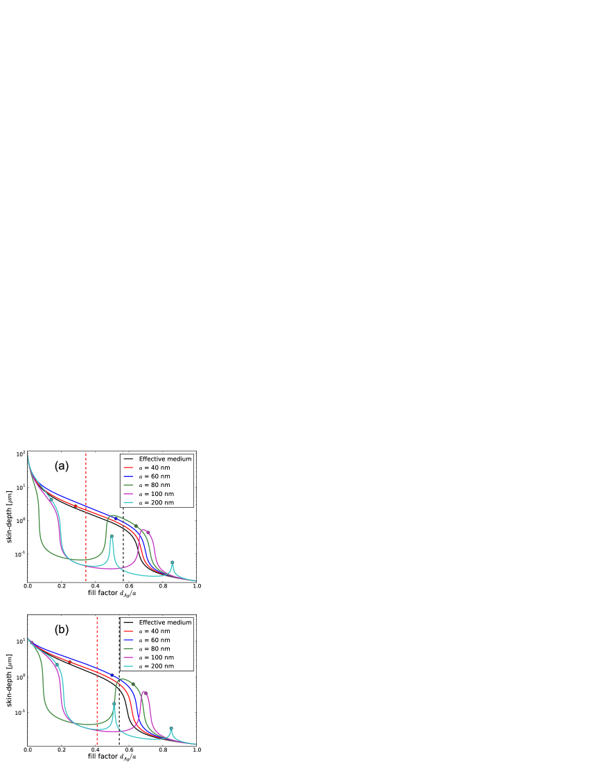
In Fig. 2 we present the effective skin depth of Ag–TiO2 and Ag–GaP periodic multilayers as a function of the filling fraction of silver for several values of the period ranging from nm to nm and for the wavelengths of nm and nm, respectively. The skin depth for a periodic structure is calculated with Eq. (8) using the effective index obtained from the Bloch wavevector given from the dispersion relation (Eq. (1)). Additionally, it is also calculated for an effective medium with , notably the two methods converge for . In the opposite limit, for large values of the period , the multilayer behaves in a resonant way remaining transparent only for the size of dielectric layers corresponding to the cavity modes exited in the dielectric layers. The locations of these modes calculated with Eq. (7) are shown with circles. In a periodic structure with sufficiently thin metallic layers ( nm) these modes broaden into a band, which is reflected by the non-resonant behavior of skin depth in Fig. 2 for small fill-factors. Nonetheless, the specific shape of the field repeated in subsequent coupled cavities is also observed already within the band when the condition (7) applies. We will further demonstrate such a case for and . Moreover, the filling factors which under EMT satisfy the conditions of diffraction-free propagation (Eq. (4)) and impedance matching (Eq. (5)) with air are also marked in the same plot with vertical dashed lines. Further, we focus on structures with the period of nm and nm, primarily due to the technological feasibility of depositing thick () multilayers with such a period but also due to their increased skin depth, as compared with the multilayers with a smaller period (See Fig. 2).
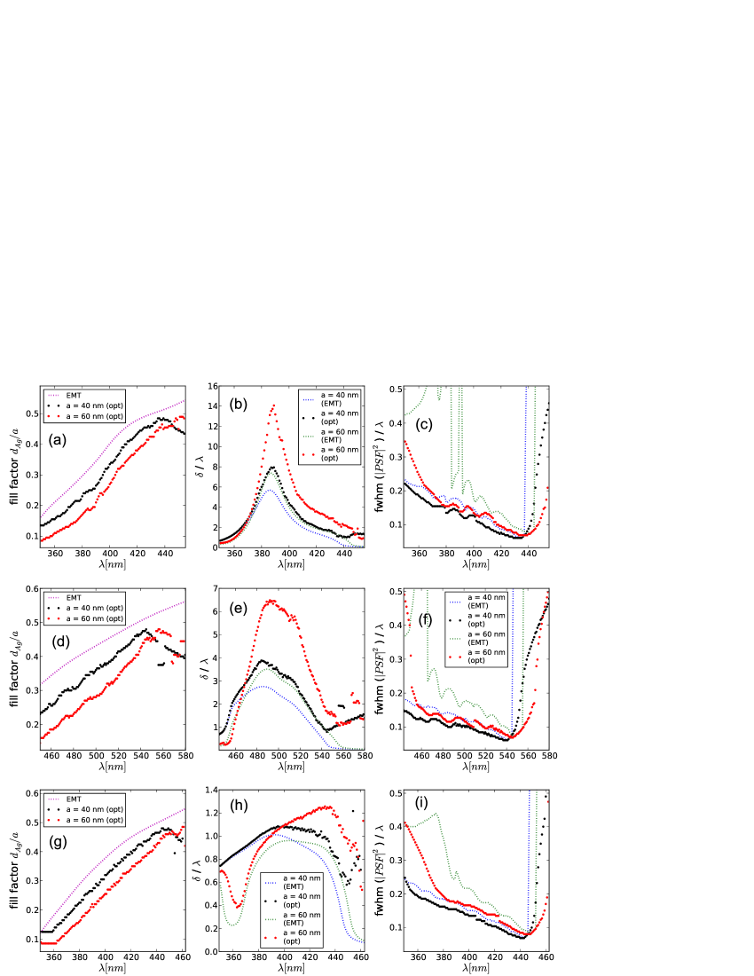
Our goal in this paper is to optimize the resolution and skin depth of multilayers in the visible wavelength range. A periodic multilayer is defined by its total thickness , period , and the fill factor . In the optimization procedure the resolution is measured for metal-dielectric stacks of the thickness equal to one wavelength and the fill factor is optimized. The optimisation is of the trade-off character, since the effective skin depth decreases monotonically with the increase of the fill factor while the of the takes minima only for specific values of the fill factor. We use the transfer matrix method (TMM) to calculate the . In order to combine high resolution and transmission efficiency, we minimise the ratio subject to the constraint that is less than .
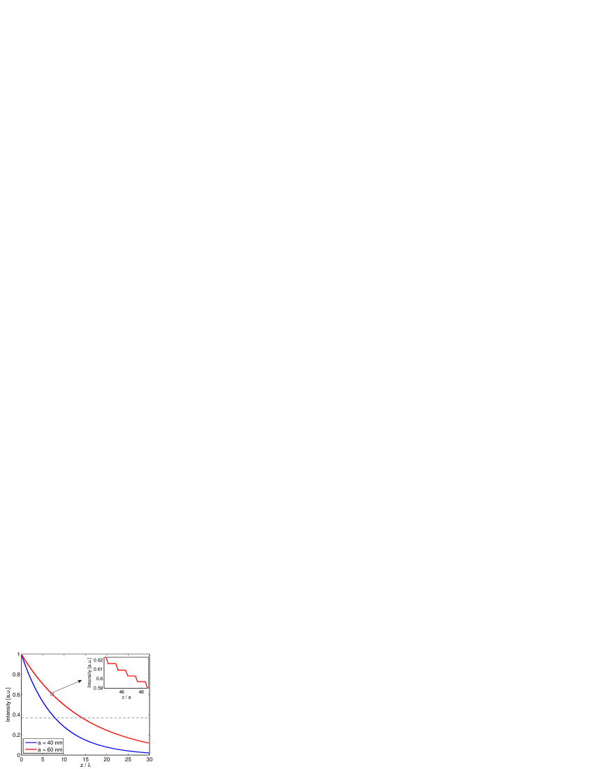
In Fig. 3 we present the optimization results for Ag–TiO2, Ag–SrTiO3 and Ag–GaP structures, respectively. The resolution and the effective skin depth of the optimised multilayers are compared with those with the fill factor obtained using the EMT-based expression for diffraction-free propagation, Eq. (4). Clearly, for a broad range of wavelengths, optimization leads to the improvement of both resolution and transmission efficiency at the same time. The largest skin depth is achieved for Ag–TiO2 structure for nm, and for Ag–GaP structure for nm. They are equal to and to , respectively. In both cases the resolution is on the order of and it is little affected by a change in . For Ag–SrTiO3 the skin depth does not exceed for any wavelength, which makes strontium titanate less interesting for fabricating thick multilayers, although the maximal value of skin depth corresponds to the resolution better than . The skin depth is larger for structures with the larger period nm than for those with nm. We illustrate this increase with a one-dimensional FDTD simulation for the Ag–TiO2 stack shown in Fig. 4. The plot includes the time-averaged Poynting vector inside an infinite structure. For both periods, light decays exponentially, however the larger thickness of elementary cell results in a slower decay rate. The inset in Fig. 4 contains a magnified part of the same plot showing that the energy is absorbed only in the silver layers, since titanium dioxide is practically lossless in the visible range. The decay rate obtained with FDTD is in perfect agreement with the value of effective skin depths calculated with the dispersion relation (1).
| Description of the multilayer | ||||
|---|---|---|---|---|
| Optimised for nm | 6.31 | 0.12 | 0.78 | |
| Coupled cavities with nm | 2.00 | 0.58 | 0.61 | |
| Optimised and homogenised | 4.22 | 0.76 | 0.42 | |
| Diffraction-free | 2.23 | 0.08 | 0.58 | |
| Fabry-Perot | 0.45 | 0.08 | 0.10 | |
| Impedance-matched, F-P | 0.90 | 0.11 | 0.33 | |
| Fabry-Perot | 1.47 | 0.11 | 0.49 | |
| Fabry-Perot | 2.27 | 0.08 | 0.59 |
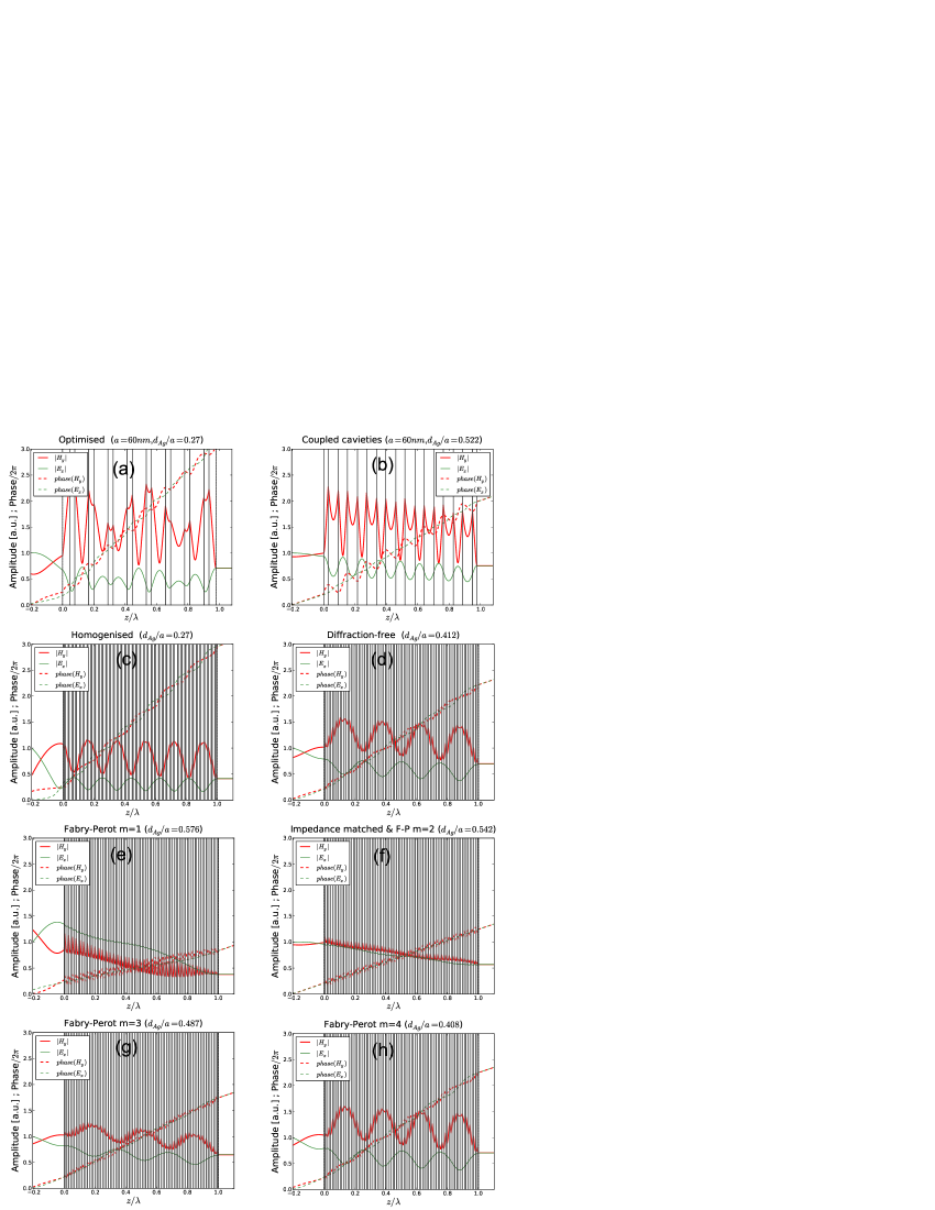
Good insight into the transmission mechanism involved in the imaging through the multilayer is gained from the internal field distribution. With this aim, in Fig. 5 we summarise the field profiles for several designs of Ag–GaP structure at nm with the total thickness of , either with nm or with extremely thin layers . We compare the following structures: the one which we have optimised, the one consisting of coupled-cavities (with the width of defined using Eq. (7) for the fundamental mode), the homogenised analogue of the optimised one (split into more layers with the filling fraction and total thickness fixed), a diffraction-free structure (fill factor calculated with Eq. (4)), and Fabry-Perot etalons of the order (with also satisfying the condition for impedance matching (5)). The corresponding filling fractions, skin depths, resolutions and intensity transmission coefficients are compared in Tab. 1. The immediate conclusion from this summary is that the optimised multilayer does not resemble the theoretical designs neither in terms of the filling fraction nor in terms of the internal field distribution. This is a strong argument for using numerical optimisation in place of simplified models based on EMT when it is important to combine a good transmission efficiency, a subwavelength resolution and to keep the total number of layers technologically feasible.
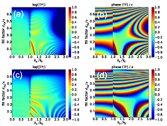
In Fig. 6 we present the amplitude and phase of amplitude transfer functions (TF) for Ag–TiO2 multilayer (at nm) and for Ag–GaP multilayer (at nm). The period and the total thickness of structure are fixed at nm and , respectively. Horizontal cross-sections of Fig. 6 include the TF calculated for a range of fill factors, and these TF depend on .
For propagating waves is the sine of the angle of incidence. The values of wavevector refer to the evanescent waves in air. Optimal fill factors for both structures are and for Ag–TiO2 and Ag–GaP multilayers, respectively. At the same time, for these values of the fill factor, the phase of TF in Fig. 6 is the flattest, while the amplitude is slowly varying. The phase is practically independent of and is similar for propagating and for evanescent components of the spatial spectrum enabling diffraction-free propagation with sub-wavelength resolution. Moreover, sub-wavelength resolution may be obtained even if the overall thickness of the multilayer is much larger than the wavelength.
Let us now illustrate the performance of the optimised multilayer. Up to now we have neglected any possible interaction between the source of the sub-wavelength-sized wavefront and the multilayer. In practice, the source may be realised using a metallic mask with sub-wavelength aperture, a kinoform with sub-wavelength relief, a plasmonic waveguide coupled to the multilayer, or with a SNOM probe. In any case, the source needs to be put in the near field or preferably be attached to the multilayer, therefore causing multiple reflections in between both elements. The system consisting of the source coupled to the multilayer analyzed as a whole, may be no longer shift invariant, although idealized source models such as a soft (uncoupled) source, or hard (strongly coupled) magnetic and electric sources may still be included in the same framework of LSI Kotynski:oer2010 . The three source models become equivalent in the absence of reflections Kotynski:oer2010 . Even though, a soft source model is assumed by us in this paper, in case of the optimised multilayer, thanks to small reflections, the FWHM of PSF is nearly the same for the three source models.
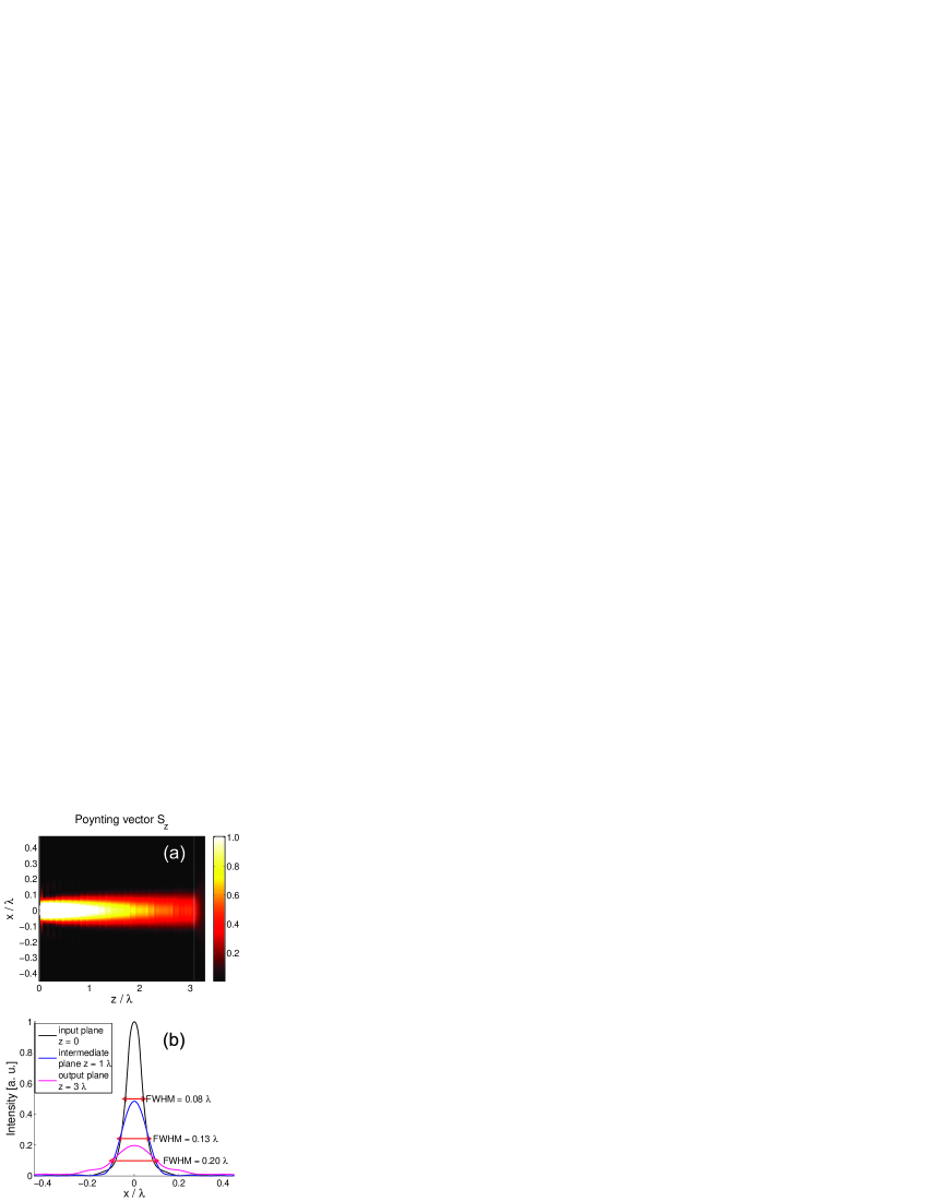
In Fig. 7 we present the results of a two-dimensional FDTD simulation of a Ag–GaP structure consisting of elementary cells with nm and fill factor equal to . We show the longitudinal component of the Poynting vector and intensity profiles at three cross-sections perpendicular to the propagation direction. The structure is illuminated with a monochromatic planewave with nm diffracted at a sub-wavelength aperture with the diameter equal to . The aperture is made in a perfect metal screen having the thickness of nm located at the distance of nm from the multilayer. Transmission through the aperture is not enhanced by resonant effects. Resonant transmission would certainly complicate our analysis, whilst our main focus here is on the transmission properties of the multilayer rather than on the efficient wavefront modulation at the scale of nm. This way, the presented results are general in the sense that they are little affected by the choice of metal used to make the mask, provided that its thickness is sufficient to make it opaque. For instance, a chromium mask with the thickness of nm could be used instead the perfect conductor giving similar results.
The sub-wavelength dimension and shape of the wavefront is preserved within the structure despite the continuous intensity decay due to the losses in metallic layers. Moreover, the at the distance of is consistent with the optimisation results obtained with the transfer matrix method and presented in Fig. 3f.
IV Conclusions
We have optimised the effective skin-depth and resolution of Ag–TiO2, Ag–SrTiO3, and Ag–GaP multilayers for imaging with sub-wavelength resolution. We have shown that multilayers with a period of nm () or larger, designed using the effective medium theory (Eqs. (4),(5),(6)) are suboptimal in terms of both resolution and effective skin depth at the same time. Still, multilayers with a large thickness of layers and with silver layers slightly thicker than the skin depth may combine a good trade-off between resolution and transmission. Optimal multilayer designs with a period of nm or nm outperform multilayers based on combined use of effective medium theory (with , and ), impedance matching and Fabry-Perot resonances in terms of transmission, with a certain deterioration of resolution. For instance, an optimised Ag–GaP multilayer consisting of only layers, operating at the wavelength of nm and having the total thickness equal to the wavelength, combines the intensity transmission coefficient of with the resolution of nm. Using EMT, the resolution may be improved to nm (See Tab. 1) but to achieve this it is necessary to increase the number of layers several-fold which is technologically challenging. We have shown that an optimised structure allows for diffraction-free guidance of a sub-wavelength sized beam of light for at least and that the transmission is not directly based on Fabry-Perot resonances. At the same time, the optimal design does not resemble the EMT-based multilayer nor the coupled-cavity multilayer in terms of either the filling fraction or the internal distribution of field making an argument for the use of numerical optimisation instead of relaying on simplified theoretical designs.
V Acknowledgements
We acknowledge support from the Polish Ministry of Science and Higher Education research project N N202 033237, the (Polish) National Centre for Research and Development research project N R15 0018 06, and the framework of European Cooperation in Science and Technology – COST actions MP0702, MP0803.
References
- (1) S. A. Ramakrishna and J. B. Pendry, Phys. Rev. B 67, 201101 (2003).
- (2) B. Wood, J. B. Pendry, and D. P. Tsai, Phys. Rev. B 74, 115116 (2006).
- (3) P. A. Belov and Y. Hao, Phys. Rev. B 73, 113110 (2006).
- (4) J. Elser, V. A. Podolskiy, I. Salakhutdinov, and I. Avrutsky, Appl. Phys. Lett. 90, 191109 (2007).
- (5) M. Scalora, G. D’Aguanno, N. Mattiucci, M. J. Bloemer, D. de Ceglia, M. Centini, A. Mandatori, C. Sibilia, N. Akozbek, M. G. Cappeddu, M. Fowler, and J. Haus, Opt. Express 15, 508 (2007).
- (6) G. X. Li, H. L. Tam, F. Y. Wang, and K. W. Cheah, J. Appl. Phys. 102, 116101 (2007).
- (7) C. Wang, Y. Zhao, D. Gan, C. Du, and X. Luo, Opt. Express 16, 4217 (2008).
- (8) M. A. Vincenti, D. de Ceglia, V. Rondinone, A. Ladisa, A. D’Orazio, M. J. Bloemer, and M. Scalora, Phys Rev. A 80, 053807 (2009).
- (9) A. Ahmadi and H. Mosallaei, J. Appl. Phys. 106, 064502 (2009).
- (10) R. Kotynski and T. Stefaniuk, J. Opt. A: Pure Appl. Opt. 11, 015001 (2009).
- (11) R. Kotynski, Opto-Electron. Rev. 18, 366 (2010).
- (12) W. H. Wee and J. B. Pendry, New Journal of Physics 12, 053018 (2010).
- (13) C. J. Zapata-Rodríguez, D. Pastor, and J. J. Miret, Appl. Opt. 49, 5870 (2010).
- (14) R. B. Nielsen, M. D. Thoreson, W. Chen, A. Kristensen, J. M. Hvam, V. M. Shalaev, and A. Boltasseva, Appl. Phys. B 100, 93 (2010).
- (15) J. B. Pendry, Phys. Rev. Lett. 85, 3966 (2000).
- (16) N. Fang, H. Lee, C. Sun, and X. Zhang, Science 308, 534 (2005).
- (17) D. O. Melville and R. J. Blaikie, Opt. Express 13, 2127 (2005).
- (18) I. A. Larkin and M. I. Stockman, Nano Lett. 5, 339 (2005).
- (19) T. Taubner, D. Korobkin, Y. Urzhumov, G. Shvets, and R. Hillenbrand, Science 313, 1595 (2006).
- (20) A. J. Hoffman, L. Alekseyev, S. S. Howard, K. J. Franz, D. Wasserman, V. A. Podolskiy, E. E. Narimanov, D. L. Sivco, and C. Gmachl, Nature Mat. 6, 946 (2007).
- (21) M. A. Vincenti, A. D’Orazio, M. G. Cappeddu, N. Akozbek, M. J. Bloemer, and M. Scalora, J. Appl. Phys. 105, 103013 (2009).
- (22) X. Li, S. He, and Y. Jin, Phys. Rev. B 75, 045103 (2007).
- (23) X. Li, F. Zhuang, and C. V. Köhnenkamp, JOSA A 26, 365 (2009).
- (24) S. He, L. Shen, and L. Wu, Phys. Rev. B 67, 235103 (2003).
- (25) P. A. Belov, C. Simovski, and P. Ikonen, Phys. Rev. B 71, 193105 (2005).
- (26) P. Markos and C. M. Soukoulis, Wave propagation. From electrons to photonic crystals and left-handed materials (Princeton University Press, Princeton and Oxford, 2008).
- (27) B. Saleh and M. Teich, Fundamentals of Photonics, 2nd ed. (John Wiley & Sons, Inc, 2007).
- (28) R. Kotynski and T. Stefaniuk, Opt. Lett. 35, 120412 (2010).
- (29) P. B. Johnson and R. W. Christy, Phys. Rev. B 6, 4370 (1972).
- (30) Handbook of Optical Constants of Solids, edited by E. Palik (Academic Press, 1998).
- (31) O. Duyar, F. Placido, and H. Z. Durusoy, J. Phys. D: Appl. Phys. 41, 095307 (2008).
- (32) A. M. Grishin, H. Kawasaki, Y. Suda, V. V. Pankov, and D. Dzibrou, Journal of Physics: Conference Series 100, 082035 (2008).
- (33) S. K. Das, P. K. A. Kumar, and S. K. Sarkar, J. Phys.: Condens. Matter 6, L445 (1994).
- (34) N. H. Cho, H. G. Kim, and S. H. Nam, J. Phys. D: Appl. Phys. 7353, 735319 (1992).