Acoustic metamaterial exhibiting four different sign combinations of density and modulus
Abstract
We fabricated a double negative acoustic metamaterial which consisted of Helmholtz resonators and membranes. Experimental data on the transmission and dispersion relation are presented. The system exhibits three frequencies where the acoustic state makes sharp transitions from density negative ( -NG) to double negative (DNG), modulus negative (-NG), and double positive (DPS) in sequence with the frequency. We observed a wide range of negative refractive index from -0.06 to -3.7 relative to air, which will allow for new acoustic transformation techniques.
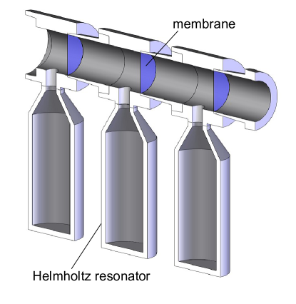
For electromagnetic media, the double negative quadrant of the - diagram suggested by Veselago became reality when a composite structure consisting of split-ring resonators and conducting wires was proposed by Pendry et al. and fabricated by Smith et al. 1 ; 2 ; 3 ; 4 . This metamaterial became a standard model for a variety of double negative media 5 ; 6 ; 7 ; 8 . Constitutive parameters for acoustic media are density () and modulus (). In previous research, an acoustic metamaterial with a negative modulus was fabricated using an array of Helmholtz resonators 9 . A negative modulus has also been generated with an array of side holes 10 . A negative density was realized using double resonant units in fluids 11 ; 12 ; 13 . Recently, a negative density was also generated with thin tight membranes 14 . Simultaneously negative density and modulus was first realized in a composite structure consisting of membranes and side holes. This structure exhibited wide double negative spectral range, but was not capable of generating large negative refractive index. In this Letter, we report fabrication of a new acoustic DNG structure which exhibited all the four different sign combinations of density and modulus, and a very wide range of negative refractive index. The structure, shown in Fig. 1, consisted of an array of interspaced Helmholtz resonators and membranes.
The main tube was made of plastic, and the method outlined in Refs. 14 and 15 was used to fabricate the membranes. Commercial 100 mL glass bottles were used as the Helmholtz resonators. The bottles were attached to the tube by plastic adaptors. To create leak-tight seals, the adapters were machined to fit both the bottle neck and the side holes made on the tube wall. The size of the neck of the Helmholtz resonator was determined by the diameter (10 mm) and length (15 mm) of the inner hole of the adaptor. The unit cell length of the metamaterial was 70 mm and the inner diameter of the tube was 32.5 mm.
Without the membranes, the structure in Fig. 1 consists solely of an array of Helmholtz resonators, which exhibits an effective modulus expressed as 9 ,
where , , , and are the modulus of the background fluid, the geometric factor, the resonance frequency of the Helmholtz resonator, and the dissipation factor, respectively. In the system detailed in Ref. 9, the dissipation was very large and thus, a negative group velocity was observed. The much larger dimensions and better quality factor of the Helmholtz resonators () in our structure make the overall dissipation quite small .The experimental results presented in this Letter can be aptly explained by neglecting ,
| (1) |
This equation shows that the effective modulus is negative in the frequency range .
Without Helmholtz resonators, our system is identical to that of a -NG structure consisting of an array of membranes 14 . In previous research, the -NG structure was found to convey a collective acoustic oscillation that was similar to a plasma oscillation. In addition, the structure exhibited an effective density given by,
| (2) |
where , the density of membrane-loaded air, is a constant that is larger than the density of air . It should be noted that the frequency dependence of Eq. (2) has the same form as that of the electrical permittivity of metals, , where is the plasma frequency. The effective density of the acoustic metamaterial is negative below the cutoff frequency .
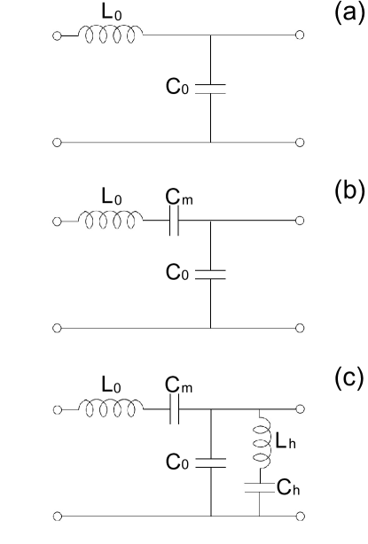
Acoustic metamaterials can be described by transmission line models, as recently demonstrated by Bongard et al. 16 . In these models, the voltage (), current (), inductor (), and capacitor () of the circuits correspond to the pressure (), volume flow (), mass of air (), and compressibility of the acoustic media (), respectively. In other words, , , , and , where and are the cross-section and unit cell volume of the tube respectively. A plain tube filled with air is represented by a circuit consisting of an array of series inductors and shunt capacitors, as shown in Fig. 2(a). The constitutive parameters for this medium are the per-unit-length inductance, , and the per-unit-length capacitance, , where is the length of a unit cell. These parameters correspond to the mass-density, , and compressibility, , of air, respectively (i.e., and ). When an array of membranes is additionally installed in the tube (making the resulting structure -NG), the unit of the corresponding transmission line becomes like that shown is Fig. 2(b) 16 , where an additional series capacitor represents the membrane.
The present acoustic composite structure consisting of membranes and Helmholtz resonators can be analyzed using the circuit shown in Fig. 2(c). The electrical resonator connected in parallel with the capacitor represents the Helmholtz resonator; the inductor and capacitor correspond to the mass of the air column in the neck and the spring action of the cavity volume, respectively. The generalized telegrapher’s equations for the voltage, and current waves, are expressed as
where and are the transmission line equivalent overall per-unit-length of impedance and admittance, respectively. For the circuit in Fig. 2(c), it can be shown that
| (3) |
| (4) |
where , , and .
The physics related to both the transmission line and the acoustic metamaterial are identical. There are also one to one correspondences for all quantities. The constitutive parameters and for the transmission line, which correspond to the effective density and modulus of the acoustic system, respectively, are obtained from the relations and . Explicit expressions are obtained from Eqs. (3) and (4),
| (5) |
| (6) |
It should be noted that Eq. (1) for the -NG medium and (2) for the B-NG medium, exactly match Eqs. (5) and (6), respectively. Since Eqs. (5) and (6) describe the transmission line, Eqs. (1) and (2) are simultaneously applicable to its counterpart, the present acoustic system.
Using the relations, and , the wave-vectors for the transmission line and the acoustic metamaterial are found to have the same expression,
| (7) |
where , and is the free space phase velocity; for the transmission line and for the acoustic system. Eq. (7) is identical in form to the dispersion relation for the electromagnetic metamaterial in Ref. 4.
We observed the transmission and dispersion relation using the following method. A sound source was installed on one side of the 2 m long metamaterial and an absorber was placed on the other side, so that the sound energy from the source propagating along the metamaterial tube was absorbed at the other end. The sound source was a speaker (RP-HV102, Panasonic) driven by an arbitrary function generator (33220A, Agilent). The absorber, constructed via a method similar to that described in Ref. 14 and 15, absorbed most of the incoming energy and allowed only a small reflection. Thus, the acoustic wave propagating in the metamaterial behaved as if it extended to infinity. Transmission data were obtained with by miniature condenser type microphones (MS-9600, Neosonic) placed in front of the source and at a position 1.5 m away from the source. Phase velocity data were obtained by comparing the phases of the sinusoidal signals from detectors placed at two positions and separated by a given distance.
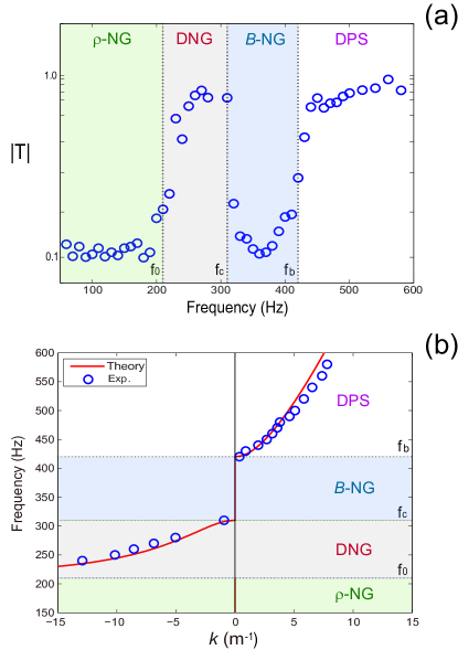
The transmission data are shown in Fig. 3(a). There are two stop bands in the frequency ranges and where the wave-vector in Eq. (7) is imaginary. There are also two pass bands, in the frequency ranges and . The phase velocity was measured as a function of the frequency, and using the relation , the wave-vector data were obtained as shown in Fig 3(b). The sign of the phase velocity is assigned to be negative when its direction is opposite that of energy flow. Waves moving towards the source was observed in the frequency range (negative phase velocity). In the upper pass band, , the waves moved away from the source (positive phase velocity). The experimental data are in excellent agreement with the theoretical expectations, which therefore confirms the validity of the present analysis using the transmission line model, because any error in the theory would have caused a deviation from the observations.
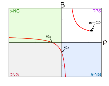
Veselago used - diagram 1 to introduce the concept of single negative and double negative electromagnetic media, but no investigation has been reported so far on representing the states of the metamaterial as the points in the - plane. In all metamaterials, the values of the constitutive parameters, which determine all the wave characteristics, vary with the frequency. Therefore we shall call a set of particular values of the constitutive parameter as an acoustic or optical state of the medium and represented it as a point in the - or - diagram. As the frequency varies, the point moves in the plane, and the trajectory forms a graph of the available states. Many of the characteristics of the metamaterial can conveniently be obtained from the graph.
In our structure, the transition frequencies were observed to be, Hz, Hz, and Hz. Substituting these values into the Eqs. (1) and (2), we obtained the graph in the - plane as shown in Fig. 4. At low frequencies, the curve starts out from the 2nd quadrant and moves to the right as the frequency increases until it hits the -axis at . For the next frequency band, , the curve passes through the 3rd quadrant, where, the ratio varies from zero to infinity, indicating a wide range of refractive index. Indeed, we observed the index relative to air varying continuously with the frequency from -0.06 at 310 Hz to -3.7 at 230 Hz (see the wave-vector data in Fig 3(b)). The line in the fourth quadrant corresponds to the frequency range, . At , the modulus diverges to . The states above the frequency are represented by the curve in the 1st quadrant, which started from and approached to the asymptotic value indicated by the ”” in the figure. Consequently the curve swept through all the four quadrants of the - plane. Therefore, our structure exhibits -NG, DNG, -NG, and DPS states in sequence with the frequency.
In summary, we described the fabrication of a double negative acoustic metamaterial consisting of an interspaced array of membranes and Helmholtz resonators. An equivalent transmission line circuit and graphical representations in the - planes were used to analyze the structure. Sharp transitions at three frequencies, , , and , were observed to change the state of the proposed acoustic metamaterial from -NG to DNG, -NG, and DPS in sequence. In the DNG band, a broad refractive index range was observed, which may allow for new acoustic wave transformation schemes.
This research was supported by Basic Science Research Program through the National Research Foundation of Korea(NRF) funded by the Ministry of Education, Science and Technology (NRF 2010-0012562).
References
- (1) V. G. Veselago, Sov. Phys. Usp. 10, 509-514 (1968).
- (2) J. B. Pendry, A. J. Holden, W. J. Stewart, and I. Youngs, Phys. Rev. Lett. 76, 4773-4776 (1996).
- (3) J. B. Pendry, A. J. Holden, D. J. Robin, and W. J. Stewart, IEEE Trans. Microwave Theory Tech. 47, 2075 (1999).
- (4) D. R. Smith, W. J. Padilla, D. C. Vier, S. C. Nemat-Nasser, and S. Schultz, Phys. Rev. Lett. 84, 4184-4187 (2000).
- (5) K. Aydin, Z. Li, M. Hudlička, S. A. Tretyakov, and E. Ozbay, New J. Phys. 9, 326 (2007).
- (6) C. M. Soukoulis, J. Zhou, T. Koschny, M. Kafesaki, and E. Economou, J. Phys. Condens. Matter 20, 304217 (2008)
- (7) L. Peng, L. X. Ran, H. S. Chen, H. F. Zhang, J. A. Kong, and T. M. Grzegorczyk, Phys. Rev. Lett. 98, 157403, (2007).
- (8) V. Podolskiy, A. K. Sarychev, and V. M. Shalaev, Opt. Express 11, 725 (2003).
- (9) N. Fang, et al. Nature Mater. 5, 452-456 (2006).
- (10) S. H. Lee, C. M. Park, Y. M. Seo, Z. G. Wang, and C. K. Kim, J. Phys. Condens. Matter 21, 175704 (2009).
- (11) J. Li, and C. T. Chan, Phys. Rev. E 70, 055602(R) (2004).
- (12) Y. Cheng, J. Y. Xu, and X. J. Liu, Phys. Rev. B 77, 045134 (2008).
- (13) X. Hu, K.-M. Ho, C. T. Chan, and J. Zi, Phys. Rev. B 77, 172301 (2008).
- (14) S. H. Lee, C. M. Park, Y. M. Seo, Z. G. Wang, and C. K. Kim, Phys. Lett. A 373, 4464-4469 (2009).
- (15) S. H. Lee, C. M. Park, Y. M. Seo, Z. G. Wang, and C. K. Kim, Phys. Rev. Lett. 104, 054301 (2010).
- (16) F. Bongard, H. Lissek, and J. R. Mosig, Phy. Rev. B 82, 094306 (2010).
- (17) C. Caloz, and T. Itoh, Electromagnetic metamaterials - Transmission line theory and microwave applications. (Wiley, New York 2006). and references therein.