Tel: +49 9131 6877 125
Fax: +49 9131 6877 199
88email: jan.korger@mpl.mpg.de 99institutetext: Jan Korger 1010institutetext: Andrea Aiello 1111institutetext: Christian Gabriel 1212institutetext: Peter Banzer 1313institutetext: Tobias Kolb 1414institutetext: Christoph Marquardt 1515institutetext: Gerd Leuchs1616institutetext: Institute of Optics, Information and Photonics, University Erlangen-Nuremberg, Staudtstr. 7/B2, 91058 Erlangen, Germany
Geometric Spin Hall Effect of Light at Polarizing Interfaces
Abstract
The geometric Spin Hall Effect of Light (geometric SHEL) amounts to a polarization-dependent positional shift when a light beam is observed from a reference frame tilted with respect to its direction of propagation. Motivated by this intriguing phenomenon, the energy density of the light beam is decomposed into its Cartesian components in the tilted reference frame. This illustrates the occurrence of the characteristic shift and the significance of the effective response function of the detector.
We introduce the concept of a tilted polarizing interface and provide a scheme for its experimental implementation. A light beam passing through such an interface undergoes a shift resembling the original geometric SHEL in a tilted reference frame. This displacement is generated at the polarizer and its occurrence does not depend on the properties of the detection system. We give explicit results for this novel type of geometric SHEL and show that at grazing incidence this effect amounts to a displacement of multiple wavelengths, a shift larger than the one introduced by Goos-Hänchen and Imbert-Fedorov effects.
pacs:
42.25.Ja42.79.Ci42.25.Gy1 Introduction
It is well-known that a beam of light transmitted through or reflected from a dielectric interface undergoes a polarization-dependent shift of its spatial intensity distribution. The so-called Goos-Hänchen (GH) goos_ein_1947 ; artmann_berechnung_1948 effect amounts to a longitudinal shift, i.e. a displacement in the plane of incidence, while the Imbert-Fedorov (IF) shift imbert_calculation_1972 can be observed transverse to this plane. These positional shifts are connected with angular counterparts merano_observing_2009 ; aiello_duality_2009 . Both, the GH bretenaker_direct_1992 ; emile_measurement_1995 ; jost_observation_1998 ; bonnet_measurement_2001 ; merano_observation_2007 and the IF shift pillon_experimental_2004 ; dasgupta_experimental_2006 ; menzel_imbert-fedorov_2008 ; mnard_imagingspin_2009 have been verified experimentally in a number of configurations while also the theoretical understanding of those effects has advanced significantly berman_goos-hnchen_2002 ; aiello_role_2008 ; bliokh_goos-hnchen_2009 .
The IF shift is also known as the Spin Hall Effect of Light (SHEL) onoda_hall_2004 ; bliokh_conservation_2006 ; hosten_observation_2008 due to its resemblance to the Spin Hall Effect in solid state physics. It amounts to a displacement of a circularly polarized beam perpendicular to the plane of incidence, where the direction depends on the beam’s helicity or photon spin. Consequently, a linearly polarized beam will split into components of different helicity.
The geometric Spin Hall Effect of Light aiello_transverse_2009 is a novel phenomenon, which like SHEL amounts to a spin-dependent shift or split of the intensity distribution of an obliquely incident light beam. This effect depends significantly on the geometric properties of the detection system and, beyond the detection process, no light-matter interaction is required.
This article is structured as follows: In the following section the original geometric SHEL is reviewed and results not explicitly given in aiello_transverse_2009 are provided. In sections 3 and 4, we introduce a theoretical model for an arbitrarily oriented planar polarizing interface fainman_polarization_1984 ; aiello_nonparaxial_2009 and provide a scheme for its experimental realization. Finally, we find that a light beam crossing a tilted polarizing interface undergoes a shift twice as large as the one found in the case of a tilted reference frame. Therefore, the methods presented in this article lead to a straightforward measurement of the geometric Spin Hall Effect of Light.
2 Geometric Shift in a Tilted Reference Frame
The geometric Spin Hall Effect of Light aiello_transverse_2009 occurs when a circularly polarized beam of light is observed in a plane not perpendicular to its direction of propagation. This effect amounts to a spatial shift of the intensity distribution with the intensity being defined as the flux of the Poynting vector through the detector plane. We stress that the geometric SHEL only depends on the geometry of the setup (Fig. 1), the state of polarization and the effective response function of the detector.
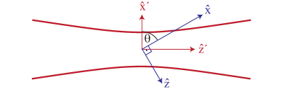
Here we give explicit results for a fundamental Gaussian light beam traveling in direction of detected in the plane (, ). The normal to the detector surface and the propagation vector unambiguously define a plane of incidence. As shown by Aiello et al. aiello_transverse_2009 , the intensity barycenter or centroid of a circularly polarized beam is shifted in direction of perpendicular to the plane of incidence. This displacement is equal to
| (1) |
The superscript indicates that the centroid was evaluated with respect to the Poynting vector flux while the subscript TD refers to a tilted detector. The shift depends on the helicity (for left or right hand circular polarization) and is prominent at grazing incidence where it amounts to a displacement larger than the wavelength .
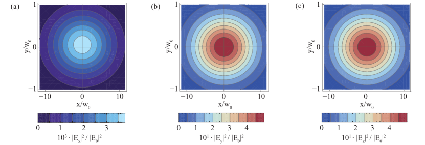
In aiello_transverse_2009 it was noted that the energy density (ED) distribution exhibits no such effect , which underlines the dependence on the detector response. The apparent discrepancy can be understood by decomposing the electric field energy density
| (2) |
into terms depending on one Cartesian component of the electric field in the detector reference frame (, , ) only. is a distribution in the observation plane and is a two-dimensional position vector. This decomposition is depicted in Fig. 2.
Analogously to (2), we decompose the barycenter of the energy density as
| (3) |
where we define
| (4) |
as the relative weight of the field component and
| (5) |
as the contribution of this component to the total shift. From a straightforward application of equations (4) and (5) to the electric field distribution of a circularly polarized Gaussian light beam one finds
| (6a) | ||||
| (6b) | ||||
| (6c) | ||||
and within the same approximation
| (7a) | ||||
| (7b) | ||||
| (7c) | ||||
where is the angular divergence of the beam mandel_optical_1995 .
Substituting equations (6) and (7) into (3) we verify that the barycenter of a light beam’s energy density
| (8) |
does not shift under rotation of the reference frame. This result underlines the scalar nature of the energy density.
We remind the reader that the Poynting vector flux through the detector surface
| (9) |
where is the surface normal, is a distribution different from and exhibits a net shift
| (10) |
where is given in (6a).
This connects the geometric SHEL with the fundamental question about the local response of a position-sensitive detector. The definition of the Poynting vector flux as the intensity is motivated by Poynting’s theorem. However, this choice is debatable as the theorem does not define the local Poynting vector unambiguously berry_optical_2009 and the definition given in equation (9) depends on the state of polarization. Contrarily, the response function of a real polarization-independent detector is more likely to be isotropic, i.e. to depend on , and thus yield .
The shift can be detected directly if a detection scheme is used where a plane of observation (, ) can be chosen arbitrarily and the effective response function depends on but not on . The polarization-dependent absorption in semiconductor quantum wells weiner_strong_1985 ; weiner_highly_1985 ; kihara_rurimo_usingquantum_2006 or single molecules sick_orientational_2000 ; novotny_longitudinal_2001 can in principle be used to build a suitable detector.
In the remaining part of this article we develop an alternative strategy to measure the characteristic shift caused by the geometric SHEL.
3 The Ideal Polarizer Model
The operation performed by a polarizing optical element is commonly only determined for normally incident beams which can be approximated as planar wave fronts. In this case the action of a polarizer is described as a projection within a plane perpendicular to the direction of propagation . This simple model fails to describe the operation of a polarizing element when no such assumptions about the light field are made, as it is the case in this article where we deal with obliquely incident beams.
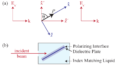
To overcome this limitation, Fainman and Shamir (FS) have proposed a model describing an arbitrarily oriented ideal polarizer fainman_polarization_1984 . They introduce a three-dimensional complex-valued unit vector and describe the action of a polarizer as follows: The electric field vector of each plane wave of the incident beam’s angular spectrum is projected onto , a unit vector perpendicular to :
| (11) | ||||
| (12) |
The model is constructed such that the operation is idempotent and does not change (Fig. 3a).
A remarkable characteristic of the FS polarizer is that rotation (around ) has no effect on a single plane wave if is parallel or perpendicular to . Hence, an ideal polarizing element cannot be used to cause an imbalance between the weights and of the electric field component parallel and perpendicular to the polarizer surface.
However, as we will show in section 5, the rotation gives rise to an effect on bounded beams similar to the geometric SHEL in a tilted reference frame. In the following section we will propose an experimental realization of an arbitrarily oriented polarizing interface.
4 Experimental realization of a universal polarizing interface
We propose a scheme using only off-the-shelf optical components to study the interaction of a light beam with a polarizing element in any geometry (Fig. 3b). For this purpose we model a real polarizer as a composite device consisting of an infinitely thin polarizing interface sandwiched between dielectric plates with a refractive index . Since commercial thin film polarizers are typically protected from the environment by either a substrate or a coating on each face, our model is close to the realistic scenario.
The interaction of the light field with an air-dielectric boundary is polarization-dependent and changes the direction of propagation of a plane wave. Those well-known effects, described by Snell’s law of refraction and Fresnel’s formulas hecht_optik_2005 , are caused by the refractive index step. At grazing incidence refraction is so severe that inside the front dielectric plate the angle between the direction of propagation and the surface normal is always significantly smaller than the corresponding angle in air. Therefore, it is desirable to eliminate the change of the refractive index at the physical boundary. This can be done, for example, by embedding the glass-polarizer-glass system in an index-matched environment. As a side effect this also eliminates unwanted Imbert-Fedorov and Goos-Hänchen shifts.
It is not common for vendors to specify the behavior of polarization optics under non-normal incidence. Measurements in our laboratory using the proposed scheme indicate that the FS model is suitable to describe a tilted polarizing interface. A detailed investigation will be reported elsewhere.
5 Geometric Shift at a Polarizing Interface
In section 2, we described the geometric SHEL as an effect which occurs for a light beam in vacuum when the plane of observation is tilted with respect to the direction of propagation. The predicted shift depends on specific assumptions about the detection process and, therefore, cannot be easily verified. In this section, we shall show that an ideal polarizer performs an operation on a light beam that amounts to the characteristic geometric SHEL shift independent of the properties of the detection system.
As in the case of the tilted detector, we assume the incident beam to travel in direction of and to have a fundamental Gaussian profile with its barycenter at and , where (, , ) is the beam’s natural reference frame and coincides with (geometry as in Fig. 3). The polarizer shall be oriented along
| (13) |
Using dimensionless coordinates , , and where denotes the beam waist and the Rayleigh length, the fundamental solution of the paraxial scalar wave equation is:
| (14) |
Let be a complex unit vector denoting left or right hand circular states of polarization. The electric field of a fundamental Gaussian beam can be written as
| (15) |
where is the angular spread of the beam and is the transverse gradient operator haus_photon_1993 .
To apply the FS polarizer model (12), the electric field (15) must be expressed in its angular spectrum representation and the beam after interacting with the tilted polarizing element becomes:
| (16) |
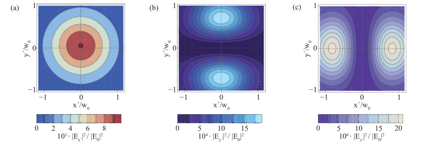
From the electric field distribution (16), we calculate the energy density of a light beam after passing through a tilted polarizer. The Cartesian components thereof are depicted in Fig. 4. Unlike in section 2, in this case the evaluation is performed in the beam reference frame (, , ) where . Decomposing the energy density barycenter as in (3) one finds
| (17a) | ||||
| (17b) | ||||
| (17c) | ||||
where is the helicity of the beam. Since we observe a collimated light beam in its natural reference frame after passing through a linear polarizer, the weights
| (18a) | ||||
| (18b) | ||||
| vanish, and, consequently, | ||||
| (18c) | ||||
The centroid of a circularly polarized beam transmitted across a tilted polarizer is thus
| (19) |
and can be measured with any detector sensitive to any weighted sum of , , and if the weight of the first term does not vanish. Standard detectors such as photodiodes and CCD cameras certainly meet this requirement.
We stress that equation (19) resembles the original result (1). The displacement introduced by the tilted polarizer
| (20) |
is twice the one found for the Poynting vector flux through a tilted plane of observation. Furthermore, this article gives a straightforward recipe to measure the shift.
Since equation (5) from aiello_transverse_2009 is generally valid, both shifts are connected to a transverse angular momentum, which occurs when the angular momentum calculated in the local frame attached to the light beam is projected upon a global frame tilted with respect to the former. For the geometric SHEL (occurring at a tilted detector), the projection is implicitly given by the definition of intensity as the flux of the Poynting vector across the detector surface. Conversely, in the case of the tilted polarizing interface, as described in this section, the projection is caused by the polarizer. Therefore, we can conclude that both shifts arise because of the projection of the intrinsic longitudinal angular momentum of a circularly polarized light beam onto a tilted reference frame. We remind the reader that beyond those geometric projections, no physical interaction occurs.
6 Conclusion
First, the original geometric Spin Hall Effect of Light, as described by Aiello et al., was illustrated using an explicit decomposition of a light beam’s energy density in a tilted reference frame. We showed that in order to observe this effect, which occurs in vacuum and amounts to a polarization-dependent shift, a suitably tailored detection system is required.
Then, a novel type of geometric SHEL occurring at a polarizing interface was introduced. To this end, we discussed a theoretical model for an ideal polarizer and suggested an experimental implementation thereof. The light field of a collimated laser beam transmitted across such a polarizer was evaluated. In the case of the polarizing interface being tilted with respect to the direction of propagation, a beam displacement resembling the original geometric SHEL was found. This shift does not depend on the detection process and can be measured in a straightforward way by using the scheme proposed in this article.
The effect derived in our work is unavoidable when a circularly polarized light beam passes through a polarizing interface tilted with respect to the direction of propagation. This underlines the importance of the geometric SHEL as polarization is a fundamental property of the light field and numerous optical devices are polarization-dependent.
Acknowledgements
A.A. acknowledges support from the Alexander von Humboldt foundation.
The final publication is available at www.springerlink.com.
References
- (1) F. Goos, H. Hänchen, Annalen der Physik 436(7-8), 333 (1947)
- (2) K. Artmann, Annalen der Physik 2, 87 (1948)
- (3) C. Imbert, Physical Review D 5(4), 787 (1972)
- (4) M. Merano, A. Aiello, M.P. van Exter, J.P. Woerdman, Nature Photonics 3(6), 337 (2009)
- (5) A. Aiello, M. Merano, J.P. Woerdman, Physical Review A 80(6), 061801(R) (2009)
- (6) F. Bretenaker, A.L. Floch, L. Dutriaux, Physical Review Letters 68, 931 (1992)
- (7) O. Emile, T. Galstyan, A.L. Floch, F. Bretenaker, Physical Review Letters 75(8), 1511 (1995)
- (8) B. Jost, A. Al-Rashed, B. Saleh, Physical Review Letters 81(11), 2233 (1998)
- (9) C. Bonnet, D. Chauvat, O. Emile, F. Bretenaker, A.L. Floch, L. Dutriaux, Optics Letters 26(10), 666 (2001)
- (10) M. Merano, A. Aiello, G.W. ’t Hooft, M.P. van Exter, E.R. Eliel, J.P. Woerdman, Optics Express 15(24), 15928 (2007)
- (11) F. Pillon, H. Gilles, S. Fahr, Applied Optics 43(9), 1863 (2004)
- (12) R. Dasgupta, P. Gupta, Optics Communications 257(1), 91 (2006)
- (13) C. Menzel, C. Rockstuhl, T. Paul, S. Fahr, F. Lederer, Physical Review A 77(1), 013810 (2008)
- (14) J. Ménard, A.E. Mattacchione, M. Betz, H.M. van Driel, Optics Letters 34(15), 2312 (2009)
- (15) P. Berman, Physical Review E 66(6), 067603 (2002)
- (16) A. Aiello, J.P. Woerdman, Optics Letters 33(13), 1437 (2008)
- (17) K.Y. Bliokh, I.V. Shadrivov, Y.S. Kivshar, Optics Letters 34(3), 389 (2009)
- (18) M. Onoda, S. Murakami, N. Nagaosa, Physical Review Letters 93(8), 083901 (2004)
- (19) K. Bliokh, Y. Bliokh, Physical Review Letters 96(7), 073903 (2006)
- (20) O. Hosten, P. Kwiat, Science 319(5864), 787 (2008)
- (21) A. Aiello, N. Lindlein, C. Marquardt, G. Leuchs, Physical Review Letters 103(10), 100401 (2009)
- (22) Y. Fainman, J. Shamir, Applied Optics 23(18), 3188 (1984)
- (23) A. Aiello, C. Marquardt, G. Leuchs, Optics Letters 34(20), 3160 (2009)
- (24) L. Mandel, E. Wolf, Optical coherence and quantum optics (Cambridge University Press, Cambridge, 1995)
- (25) M.V. Berry, Journal of Optics A: Pure and Applied Optics 11(9), 094001 (2009)
- (26) J.S. Weiner, D.A.B. Miller, D.S. Chemla, T.C. Damen, C.A. Burrus, T.H. Wood, A.C. Gossard, W. Wiegmann, Applied Physics Letters 47(11), 1148 (1985)
- (27) J.S. Weiner, D.S. Chemla, D.A.B. Miller, H.A. Haus, A.C. Gossard, W. Wiegmann, C.A. Burrus, Applied Physics Letters 47(7), 664 (1985)
- (28) G.K. Rurimo, M. Schardt, S. Quabis, S. Malzer, C. Dotzler, A. Winkler, G. Leuchs, G.H. Döhler, D. Driscoll, M. Hanson, A.C. Gossard, S.F. Pereira, Journal of Applied Physics 100(2), 023112 (2006)
- (29) B. Sick, B. Hecht, L. Novotny, Physical Review Letters 85(21), 4482 (2000)
- (30) L. Novotny, M. Beversluis, K. Youngworth, T. Brown, Physical Review Letters 86(23), 5251 (2001)
- (31) E. Hecht, Optik, 4th edn. (Oldenbourg, München, 2005)
- (32) H.A. Haus, American Journal of Physics 61(9), 818 (1993)