Magneto-optical control of Förster energy transfer
Abstract
We introduce a general framework to study dipole-dipole energy transfer between an emitter and an absorber in a nanostructured environment. The theory allows us to address Förster Resonant Energy Transfer (FRET) between a donor and an acceptor in the presence of a nanoparticle with an anisotropic electromagnetic response. In the particular case of a magneto-optical anisotropy, we compute the generalized FRET rate and discuss the orders of magnitude. The distance dependence, the FRET efficiency and the sensitivity to the orientation of the transition dipoles orientation differ from standard FRET and can be controlled using the static magnetic field as an external parameter. Keyword: Fluorescence; FRET; surface plasmon; Förster radius; Magneto-optics; Nanoparticle; Quenching.
I Introduction
Energy transfer between a molecule in an excited state (donor) and a molecule in the ground state (acceptor) underlies many significant photophysical and photochemical processes, from photosynthesis to fluorescence probing of biological systems. It is also of interest in nanophotonics where efficient transfer of optical excitations on subwavelength scales is a key issue. Depending on the separation between the donor (D) and the acceptor (A), the process can be described accurately by various theories accounting for the electromagnetic interaction between the two species. For a D-A distance range on the order of 2-10 nm, which is relevant for photochemical studies and nanophotonics, the well established Förster theory Forster59 based on quasi-static dipole-dipole interaction has been very successful. It shows that while FRET is a very useful process which can be used, for example, as a ruler for spectroscopic measurementsStryer78 , it is a rather weak process which goes down as the inverse sixth power of the D-A separation. In fact, one can introduce a length scale known as the Förster distance at which FRET is 50% efficient and it is found that is on the order of a few nanometers in most practical situations. For even smaller distances, Dexter Dexter53 recognized that electronic exchange and multipolar interactions become important and a full quantum mechanical treatment must be implemented. On the other hand, in the large distance regime (non-negligible compared to the wavelength), full electrodynamics is needed to account for retardation effects. In this work, we will focus on the so-called Förster resonance energy transfer (FRET) when D and A are located in the vicinity of a nanoparticle. In this three-body configuration, we will extend the FRET formalism and show that the presence of the external nanostructure introduces interesting degrees of freedom. In the case of a nanoparticle with an anisotropic dielectric response (e.g., a nanoparticle made of a ferromagnetic material exhibiting a magneto-optical response), the distance dependence, the orientation dependence and the strength of the FRET efficiency can be changed substantially. In the case of a magneto-optical anisotropy, it can in principle be controlled using the static magnetic field as an external control parameter.
II Generalized FRET Theory
In this section, we introduce a generalized formalism to compute the FRET rate that allows us to deal with a D-A system in interaction with a nanostructured environment. This formalism includes as a particular case the standard Förster theory.
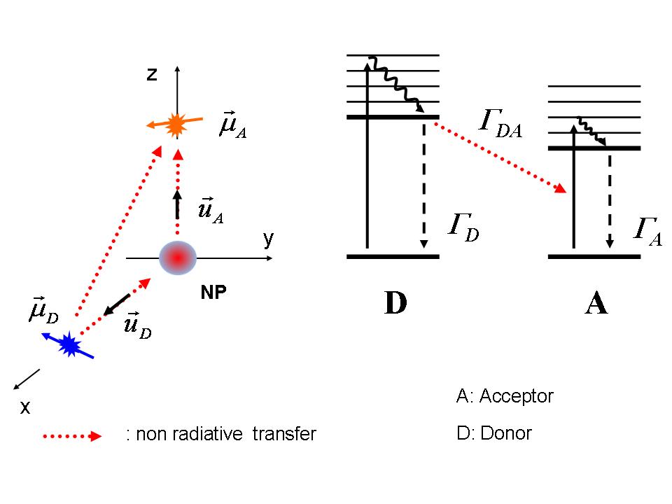
Let us consider a donor (emitter) and an acceptor (absorber) with arbitrary locations and orientations of transition dipoles, in the vicinity of a nanostructure, as illustrated in Fig. 1 (a single nanoparticle is represented for the sake of illustration, but the theory presented in this section is not restricted to this geometry). We denote by and by the position and the direction of the transition dipole of the acceptor and donor, respectively. For electric-dipole transitions and in the weak-coupling regime, the normalized FRET rate can be calculated from the electric Green function which describes the electromagnetic response of the environment. It takes the form (the full derivation is given in Appendix A):
| (1) |
In this expression, is the energy transfer rate from donor to acceptor, the decay rate of the donor in free space and the emission frequency. is the normalized emission spectrum of the donor, and the function is defined by
| (2) |
where is the electric dyadic Green function that describes the environment of the donor and acceptor. It is defined as follows: For a point electric dipole located at position and oscillating at frequency , the electric field radiated at position reads . The expression of the FRET rate given in Eqs (1-2) is very general, and can be applied to an arbitrary geometry, provided that the Green dyadic is known. Thus Eqs (1-2) establish the basis for a generalized FRET theory. In particular, it shows that the FRET signal, as any fluorescence signal, is strongly dependent on the environment Novotny .
II.1 FRET rate in free space
To recover the standard FRET formalism corresponding to a D-A couple in free space, one can rewrite Eq. (1) as follows
| (3) |
with
| (4) |
and simply replace by the dyadic Green function of free space. In the quasi-static limit , with the unit vector in the direction of (). This leads to the well-known expression of the standard FRET rate Novotny ; Forster59 ; Gersten84 ; Hua85 :
| (5) |
where is the distance between the acceptor and the donor, and where the Förster radius is readily identified as follows
| (6) |
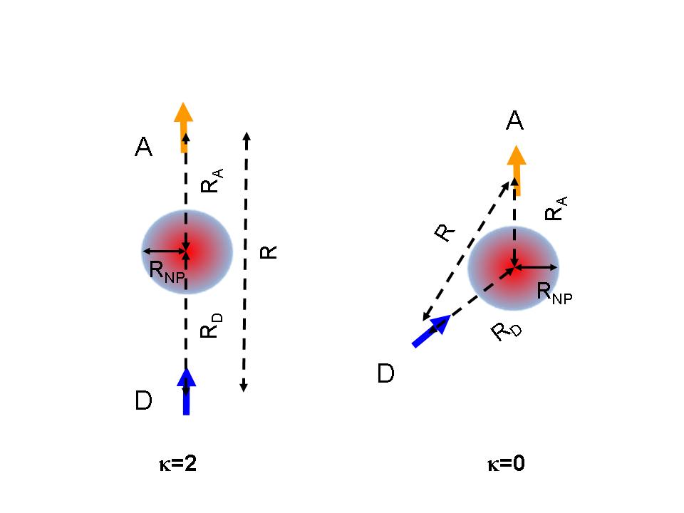
In this expression, is the orientational factor, with the unit vector along the axis of the D-A couple. The orientational factor can take values from 0 (perpendicular transition dipoles) to 2 (parallel transition dipoles).
II.2 FRET rate in the presence of a nanoparticle with an anisotropic dielectric response
In principle, the presence of a nanostructure close to a D-A couple will modify the emission and absorption by the transition dipoles. The modifications are accounted for by the dyadic Green function that describes the electrodynamic response of the environment, through the function entering Eq. (1). This formalism leads to a very general treatment of the FRET transfer mediated by an external nanostructure, such as a nanoparticle with an anisotropic response. It permits a study of the influence of many parameters of practical relevance, such as the orientation of the transition dipoles, or the shape and material properties of the nanoparticle.
In the presence of the nanoparticle, described itself in the electric-dipole approximation, the full dyadic Green function reads
| (7) |
where is the center of the nanoparticle and its polarizability tensor. In the following we assume that the nanoparticle is located at the origin and set . Equation (1) can be rewritten as follows
| (8) |
where the function is given by
| (9) |
Using again the quasi-static limit for the free-space dyadic Green function , we obtain
| . | (10) |
where is the distance between the acceptor and the nanoparticle, is the distance between the donor and the nanoparticle, and , . This expression clearly shows the contribution of the different non-radiative energy transfer channels: The direct (standard) Förster transfer , the energy transfer mediated by the nanoparticle , and an interference term accounting for the phase shift between the two channels. In the following, we will focus on the role of the nanoparticle and compute the FRET rate . In the spirit of the Förster radius, we introduce the distance such that
| (11) |
This new length scale will be denoted by polarization coupling radius. Using this quantity, the FRET rate mediated by the nanoparticle can be rewritten as
| (12) |
This compact expression is convenient for the analysis of the FRET rate mediated by a nanoparticle, and its derivation is a key step in the present paper. An important result is that the distance dependence differs from that of standard (free space) FRET. Moreover, the polarization coupling radius allows us to compare the indirect FRET rate (i.e., mediated by the nanoparticle) and the standard free-space FRET rate.
For the sake of illustration, let us consider the situation in which the three bodies are aligned (see Fig. 2(a)), with and (). In this case, we obtain
| (13) |
This simple expression shows that the ratio is the crucial parameter that describes the influence of the nanoparticle on the FRET rate. For , the nanoparticle enhances the FRET transfer, while for , the FRET becomes exclusively driven by the direct transfer. In order to get insight into the meaning of the polarization coupling radius, let us assume that the polarizability of the nanoparticle varies smoothly on the frequency range of the spectral overlap between and . We can rewrite Eq. (11) as follows
| (14) |
In this condition, the polarization coupling radius depends only on the polarizability tensor of the nanoparticle. Such a framework allows us to put forward explicitly the relevant length scales involved in the FRET mechanism mediated by the nanoparticle, i.e., the Förster radius and the polarization coupling radius . In the following we use this formalism to calculate explicitly the FRET rate of a D-A couple interacting with a spherical nanoparticle exhibiting a magneto-optical response or a purely metallic response.
II.3 Spherical magneto-optical nanoparticle
Ferromagnetic materials exhibit magnetic anisotropy that can be controlled by an external static magnetic field. At saturation, their magnetization influences the dielectric function, that exhibits the so-called magneto-optical response. A spherical nanoparticle made of a material with a magneto-optical response can be described by an anisotropic electric polarizability with radiative corrections Saenz10
| (15) |
where is the quasi-static polarizability. For magneto-optical materials (gyrotropic material) in the presence of a static magnetic field, it reads
| (16) |
where is the volume of the nanoparticle and is the dielectric tensor, given by
| (17) |
In this expression is the direction of the magnetization inside the particle, the diagonal part of the dielectric tensor and is the magneto-optical coefficient. Let us stress that expression (15) of the polarizability is consistent with energy conservation (or, equivalently, the optical theorem)Draine88 ; Lakhtatia90 . In the case of a pure metal, the same expression of the polarizability holds, with an isotropic dielectric function . In the present paper, we use bulk dielectric functions (no finite-size effects), which is a reasonable approach when the sizes involved remain larger than a few nanometers FordWeber84 .
III Discussion
The formalism in the previous section has shown the crucial role of the polarization coupling radius on the FRET rate mediated by a nanoparticle. In this section, using experimental data for the dielectric function of different metallic and magneto-optical materials Palik85 , we compute the ratio , where is the radius of the nanoparticle, and study its dependence on different parameters of practical relevance: The emission wavelength of the donor, the radius of the nanoparticle, and the material properties.
III.1 FRET mediated by a metallic nanoparticle
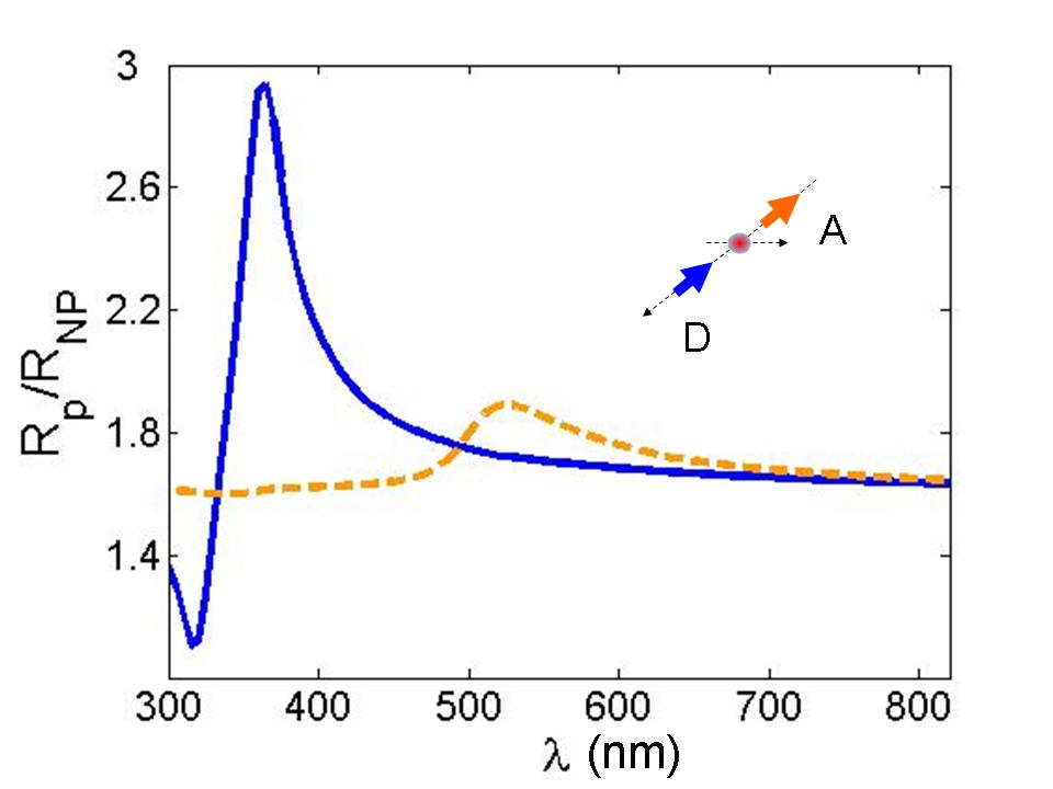
Noble metals are known to hold plasmon resonances that enhance, for example, the polarizability of nanoparticle. Since the polarization coupling radius directly depends on the polarizability, one can expect a substantial influence of the plasmon resonance on the FRET rate mediated by the nanoparticle. This is indeed what we observe in Fig. 3, in which we have plotted the ratio with nm) versus the emission wavelength of the donor for gold and silver, that are common materials in studies of fluorescence enhancement or quenching. We have considered the aligned configuration, with , , and [see Fig. 2(a) for a sketch of the aligned geometry]. The plasmon resonance is visible in both cases, leading to an enhancement of . For instance in the case of silver, one reaches ; for gold, one has . In the particular conditions and , corresponding to the validity of Eq. (13), we obtain an enhancement factor of the FRET rate on the order of for silver and for gold. For a D-A couple working at plasmon resonance with these materials, we conclude that FRET is mainly driven by the nanoparticle. Incidentally, any change of the dielectric property of the nanoparticle will be reflected in a modulation of the FRET rate. Modulation of the dielectric response can, be achieved, e.g., through the magneto-optical effect that we consider in the following.
III.2 Controlling FRET through the magneto-optical interaction
A magneto-optical nanoparticle can be described using the polarizability in Eqs. (15-17), together with experimental data for the dielectric function of well known magneto-optical materials Palik85 . In this section, we compute the ratio and study the influence of different parameters, such as donor emission wavelength, nanoparticle material and size.
We show in Fig.4 the ratio (with nm) versus the emission wavelength of the donor for different materials that are known to exhibit a magneto-optical response (Nickel, Iron and Cobalt), and in the same aligned configuration as in Fig. 3. We observe a smoother behavior than in the case of noble metals (Fig. 3), since plasmon resonances are strongly damped by absorption in these magneto-optical materials. For these materials, the enhancement factor of the FRET rate is on the order of , showing that in this case the FRET rate is also driven by the nanoparticle.
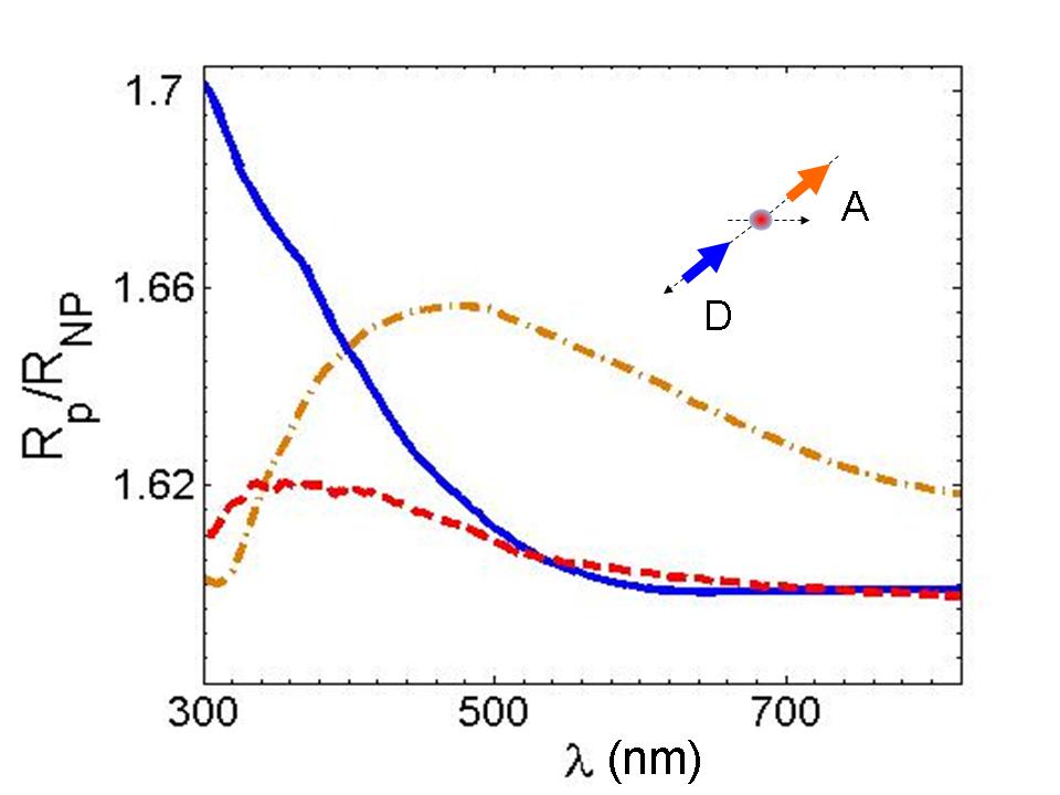
Figure 5 shows a computation of the ratio with the same materials as in Fig. 4, but in the case of an orthogonal configuration with , , and [see Fig. 2(b) for a sketch of the orthogonal geometry]. The magnetization is orthogonal to the plane containing the D-A couple and the nanoparticle. Let us stress that, in this configuration, the FRET rate vanishes in absence of an external static magnetic field due to the orthogonality of the donor and acceptor transition dipoles (). Although one observes that remains smaller than one, the possibility of inducing a FRET rate driven only by the polarization anisotropy of the nanoparticle is an interesting result, showing the potential of magneto-optical nanoparticles for FRET. On the one hand, the anisotropic response allows to couple molecules for which standard FRET gives a vanishing signal due to orientational mismatch. On the other hand, the possibility of controlling the magneto-optical response with a static magnetic field as an external parameter could allow to tune or modulate the FRET rate, which can be an advantage, e.g., to increase the sensitivity of the detection process.
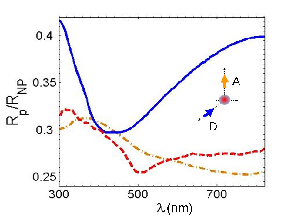
III.3 Distance dependence of the FRET rate
The of free-space FRET (Förster’s theory) is a well-known feature of non-radiative dipole-dipole-coupling. In the presence of an external body, this distance dependence is obviously more involved, as shown by the general theory that we introduced. In Eq. (12), we see a dependence on both the donor-nanoparticle distance () and the acceptor-nanoparticle distance (). In order to get insight into the dependence of the generalized FRET rate on the acceptor-nanoparticle distance only, we arbitrary fix the donor-nanoparticle distance as follows: with (note that the opposite choice can be made). In this case, the dependence of the FRET rate on the acceptor-nanoparticle distance is given by
| (18) |
From this expression, we see that we recover an inverse sixth power dependence, as in standard FRET, but with the D-A distance replaced by the acceptor-nanoparticle distance. This simply reflects the mechanism underlying the FRET rate mediated by the nanoparticle channel, which can be seen as a series of non-radiative energy transfer from the donor to the nanoparticle followed by another transfer from the nanoparticle to the acceptor. It is known that non-radiative energy transfer through dipole-dipole interaction between an emitter and a nanoparticle leads to the distance dependence that is recovered hereCarminati06 ; Seelig07 ; colasdes08 . Another important output of Eq. (18) is that from the knowledge of the ratio , we know exactly what the critical acceptor-nanoparticle distance that separates the quenching and enhancement regimes of FRET mediated by the nanoparticle.
IV Conclusion
We have solved the Förster energy transfer problem in a three-body configuration, involving two fluorophores close to a nanoparticle with an anisotropic dielectric response. Using a Green function formalism, we have shown that the angular contribution, the distance behavior and the influence of the polarizability tensor of the nanoparticle can be identified and separated. The distance dependence is controlled by a new distance that depends of the polarization properties of the nanoparticle. We have illustrated the formalism in the case of a magneto-optical nanoparticle for which the degree of anisotropy can be controlled by an external static magnetic field, and we have discussed potential application for FRET tuning and modulation. Here, we have presented a proof of concept. Further work should focus on enhancing the (weak) magneto-optical FRET signal. We have illustrated the formalism also for the well known metallic nanoparticle, showing that this formalism could furnish insight in the understanding of the good quantities controlling this process.
V Appendix
The expression of the normalized energy transfer can be obtained by treating the acceptor as classical harmonic damped dipole oscillating at frequency . In this approach the normalized fluorescence energy transfer is equivalent to the normalized power emitted by the classical dipole. One writes , where is the power transmitted from donor to acceptor in the presence of the environment and is the power emitted by the donor in absence of acceptor and in free-space. can be written as
| (19) |
with , , the donor and acceptor dipole respectively.
The power absorbed by the acceptor can be written
| (20) |
assuming that the acceptor is a polarizable molecule of fix direction (), with , we may write
| (21) |
allowing us to write the normalized FRET transfer as
| (22) |
and using the absorption cross section expression and the imaginary part of the free space dyadic green function it leads to
| (23) |
Introducing the normalized emission spectrum of the donor , we finally obtain the important result
| (24) |
with
| (25) |
Acknowledgements.
VI Acknowledgements
This work has been supported by the EU Project Nanomagna under contract NMP3-SL-2008-214107.
References
- (1) T. Förster, Ann. Phys. 437, 55 (1948); Discuss. Faraday Soc. 27, 7 (1959).
- (2) D. L. Dexter, J. Chem. Phys. 21, 836 (1953).
- (3) L. Stryer, Annu. Rev. Biochem. 47, 819 (1978).
- (4) L. Novotny, B. Hecht, Principles of Nano-optics, Cambridge University Press, 2006.
- (5) J. I. Gersten and A. Nitzan, Chem. Phys. Lett. 104, 31 (1984).
- (6) X. M. Hua, J. I. Gersten, and A. Nitzan, J. Chem. Phys. 83, 3650 (1985).
- (7) S. Albaladejo, R. Gómez-Medina, L. S. Froufe-Pérez, H. Marinchio, R. Carminati, J. F. Torrado, G. Armelles, A. García-Martín, and J. J. Sénz,Opt. Express 18, 3556-3567 (2010)
- (8) E. D. Palik, Handbook of Optical Constants of Solids (Academic, New York, 1985).
- (9) B.T. Draine, Astrophys. J. 333, 848 (1988).
- (10) A. Lakhtatia, Opt. Commun. 79, 1 (1990).
- (11) G.W. Ford, W.H. Weber, Phys. Rep. 113, 195 (1984).
- (12) R. Carminati, J.-J. Greffet, C. Henkel, and J.M. Vigoureux, Opt. Commun. 261, 368-375 (2006).
- (13) J. Seelig, K. Leslie, A. Renn, S. Kühn, V. Jacobsen, M. van de Corput, C. Wyman, and V. Sandoghdar, Nano Letters 7 (3), 685-689 (2007)
- (14) G. Colas des Francs, A. Bouhelier, E. Finot, J.-C. Weeber, A. Dereux, C. Girard and E. Dujardin. Optic Express, 16, 17654-17666 (2008).