Generation of Dicke states using adiabatic passage
Abstract
Entangled states of two ions are realized by using an adiabatic process. Based on the proposal by Linington and Vitanov (2008), we have generated Dicke states in optical qubits of two 40Ca+ ions by applying frequency-chirped optical pulses with time-dependent envelopes to perform rapid adiabatic passage on sideband transitions. One of the biggest advantages of adiabatic approaches is their robustness against variations in experimental parameters, which is verified by performing experiments for different pulse widths or peak Rabi frequencies. Fidelities exceeding 0.5, which is the threshold for inseparable states, are obtained over wide ranges of parameter values.
pacs:
03.67.Bg, 37.10.TyI Introduction
Multipartite entanglement plays a central role in quantum information science. Entangled states have been generated and studied in various systems, including photons and trapped ions Häffner et al. (2005); Leibfried et al. (2005); Blatt and Wineland (2008); Prevedel et al. (2009); Wieczorek et al. (2009). Of multipartite entangled states, a set of states known as Dicke states Dicke (1954) has recently been attracting interest. Dicke states are entangled states that are symmetric with respect to particle permutations. They are defined as
| (1) |
where and are respectively the number of particles and excitations and indicates the sum over all particle permutations. W states, a subset of Dicke states with a single excitation, have been produced and investigated using up to eight trapped ions Häffner et al. (2005). Dicke states of up to six photons have been generated and their unique characteristics, such as entanglement persistency against photon loss and projective measurements, have been studied Eibl et al. (2004); Kiesel et al. (2007); Prevedel et al. (2009); Wieczorek et al. (2009).
Linington and Vitanov (2008) proposed a relatively simple and effective method for generating Dicke states in a string of ions that utilizes frequency-chirped optical pulses. The method described in Ref. Linington and Vitanov (2008) can be used to generate Dicke states for arbitrary numbers of particles and excitations. For small numbers of excitations , resonant pulses can also be used to produce Dicke states , although in this case perfect fidelity is possible only when . Hume et al. (2009) analyzed the fidelity attainable by a method using resonant pulses and experimentally demonstrated it using two 25Mg+ ions and an ancillary 27Al+ ion.
In this article we report the generation of an entangled state of two ions, , by using rapid adiabatic passage (RAP) Treacy (1968); Vitanov et al. (2001); Wunderlich et al. (2007) in a sideband transition of – of 40Ca+. We also analyze the effects of using optical pulses with time-dependent envelopes for RAP. Such pulses produce time-dependent AC Stark shifts that may result in violation of adiabaticity. One advantage of using adiabatic passage to generate Dicke states is its robustness against parameter variations. Using an AC-Stark-shift compensator that cancels time-dependent AC Stark shifts, the robustness of entanglement generation is verified by varying the width and peak intensity of the optical pulse used for RAP. The method employed here can be extended to generate larger Dicke states with more particles and excitations.
II Principles
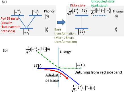
Fig. 1 depicts the basic concept for generating Dicke states using RAP. The internal states of two ions and the motional Fock states of their axial center-of-mass (COM) mode are respectively denoted as and , where represents a qubit state of each ion and denotes the motional quantum number.
The ions are initially prepared in a motional Fock state using either pulses or RAP pulses on the blue (red) sideband and a carrier transition that are addressed to only one of the ions; e.g., a blue sideband pulse followed by a carrier pulse, both of which are addressed to the first ion, to transfer the ions as .
An entangling operation is performed with a laser beam tuned closely to , which excites the red sideband transition, where () is the laser (atomic resonance) frequency and is the secular frequency of the axial COM mode. This preserves the total number of excitations , where is the number of atoms in ; hence, is coupled only to and , and the relevant states form a V-shape diagram.
When the ions are excited by a single laser, the time dependences of the Rabi frequency for each ion are the same up to a proportionality factor. In addition, the detuning for each ion will also be the same when the difference in level shifts due to Zeeman or Stark effects can be neglected. In such a case, the system can be further simplified by a unitary transformation in the upper manifold with spanned by and , and it becomes equivalent to a two-state system and an uncoupled (dark) state (right diagram in Fig. 1(a)). This is one of the simplest examples of a more general prescription known as the Morris–Shore transformation Morris and Shore (1983); Rangelov et al. (2006). If the two ions have the Rabi frequencies of the same time dependence, the two-state system will consist of and a Dicke state (or a Bell state) , with the uncoupled state being equal to another Bell state with the same , .
Thus, starting from , either a pulse or RAP on the red sideband transition can be used to transfer the population to the desired final state . Fig. 1(b) shows the adiabatic potentials for the case of RAP and plots the energy levels with different detunings for the red sideband pulse. The population follows the lower curve to be adiabatically transferred from to . (Here, the Rabi frequencies are assumed to be constant for simplicity, while it is usually varied in actual experiments. )
This scheme can be extended to more ions and more excitations to produce . The latter extension requires extending the Morris–Shore transformation to multilevel ladders Rangelov et al. (2006); in this case, the initial state is coupled to the final state by a ladder with energy levels. With unitary operations induced by resonant optical pulses, the dynamics in this multilevel diagram never produce a unit population in the final state Retzker et al. (2007); Hume et al. (2009), whereas when using RAP, such an objective can be accomplished, at least under ideal conditions Linington and Vitanov (2008).
III Experimental Procedure
The trapping system and laser setup used in the present study are similar to those described in Toyoda et al. (2010). In brief, we use two in a linear trap with center-of-mass frequencies of MHz. As the qubit states and are used, and the transition between them is excited by a titanium–sapphire laser beam with a wavelength of 729 nm. The envelopes and frequencies of the optical pulses used for RAP are controlled by an acousto-optic modulator (AOM) in a double-pass configuration. Linear frequency chirping of the rf for the AOM is performed using a direct digital synthesizer. The pulse envelope is varied by using a mixer with a digital-to-analog converter as an input. Both the direct digital synthesizer and the digital-to-analog converter are controlled by a field-programmable gate array.
Individual addressing is required to prepare motional Fock states in advance to the entangling operation, which is here done using AC Stark shifts generated by a 854 nm beam that is off resonance with the – transition. This beam, which has a intensity radius of 15 m, is applied to the two ions at 45 degrees to their axis, with a small offset from their center to produce different shifts for the ions. Typical shifts for the two ions are (10, 100) kHz, respectively.
After Doppler cooling and ground-state cooling of axial COM and stretch modes, average quantum numbers are obtained, respectively. A motional Fock state is prepared by applying a blue sideband and a carrier pulse in series to one ion using the individual addressing technique described above. An entangling operation is then performed by applying a chirped pulse to the red sideband transitions of both ions. A chirp width of 200 kHz typically used; i.e., the detuning is swept from 100 to +100 kHz.
We also use an AC-Stark-shift compensator in experiments to verify the robustness of Dicke state generation (see §VI). To realize this, we use another AOM in a single-pass configuration. Two RF signals with independently variable frequencies and powers, one of which is for direct excitation and the other for AC-Stark-shift compensation, are combined and fed to this AOM. The output of this AOM is directed into a single-mode optical fiber and then into the above-mentioned double-pass AOM system, and it is applied to ions.
IV Result of Dicke state generation
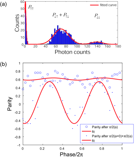
The fidelity for generating a Dicke state , , is analyzed by performing global rotations and projective measurements. The sum of the diagonal elements, is estimated by performing projective measurements immediately after the RAP pulse. The result is shown in Fig. 2(a). The histogram of fluorescence counts obtained by using a 397-nm laser beam is plotted. From this, is obtained.
The term containing off-diagonal elements, is estimated by parity measurements after applying a pulse with a variable phase. The parity after applying a pulse with phase is expressed as follows.
where is the parity operator. represents the rotation operation with a pulse with phase . In cases with perfect fidelity, is unity regardless of . In realistic cases, the offsets of sinusoidal fits to the measured values give the values of .
Fig. 2(b) shows parity measurement results. Open circles represent measured values of and the solid curve is a sinusoidal fit with period to the measured values. From this, is obtained. Combined with the above result for the diagonal matrix elements, the fidelity for Dicke state generation is estimated to be .
can be transferred to with a pulse, and parity measurement after such a transfer may also give an indication of entanglement. The filled circles in Fig. 2(b) represent parity after Dicke state generation followed by two pulses with the phase of the second varied. The sinusoidal oscillation with period indicates the presence of after the first pulse. By combining this result with that for one pulse described above, we estimate the fidelity for generation of to be .
V Effects of AC Stark shifts
The method used here for generating Dicke states using RAP on sideband transitions requires pulses with time-dependent envelopes to perform efficient population transfer. As is well known, when intense optical pulses are applied to sideband transitions they produce large AC Stark shifts and can cause undesirable effects such as qubit-phase rotations Häffner et al. (2003). In the sideband RAP case treated here, relevant adiabatic potentials may be deformed in unexpected ways and adiabaticity may be violated. This was avoided in the result presented above by selecting sets of parameter values such that the dynamics is not greatly affected by diabatic transitions. However, if we consider robustness against variation of parameters such as the pulse width and the peak Rabi frequency, which is one of the biggest advantages of the adiabatic method described here, we should manage AC Stark shifts appropriately.
We calculated adiabatic potentials and considered adiabaticity in the case of Dicke-state generation using sideband RAP. The calculation is based on the following time-dependent Hamiltonian in a rotating frame.
Here, () are state vectors for the th ion, , and . is the time-dependent Rabi frequency for carrier transitions, and is the detuning from their resonance. and are respectively the Lamb–Dicke parameter and the annihilation operator for the axial COM mode.
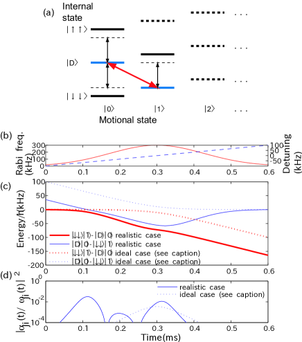
We chose the following five basis states for the calculation, , , , , and , where represents [see Fig. 3(a)]. These consist of the two states and , which are connected to each other by red sideband RAP, and states that are directly connected to these two states by carrier excitation. The laser is assumed to illuminate both ions equally. In that case, the antisymmetric Bell state becomes uncoupled with other internal states and can be excluded from consideration Morris and Shore (1983); Rangelov et al. (2006). The existence of can be neglected since it is only indirectly coupled with via through off-resonant carrier couplings. In fact, even and can be neglected when calculating energy shifts, since the AC Stark shifts of due to the couplings with those states exactly cancel each other and have negligible effects. Here, we consider these states for the sake of completeness. Therefore, the only non-negligible shift originates from the coupling between and .
Fig. 3(b) shows the time dependence of the Rabi frequency (solid curve) and detuning (dashed curve) of the assumed optical pulse. The Rabi frequencies represent those for the carrier transition. Fig. 3(c) shows the adiabatic potentials for relevant dressed states (solid curves), obtained by diagonalizing a Hamiltonian derived from the one given above. The two potentials roughly correspond to the bare states and , where . (The quantum number of the optical field is omitted for simplicity.)
The bare-state potentials for and intersect at the center (about 0.3 ms), where the adiabatic potentials for the dressed states approach each other, as expected. However, they also approach each other at 0.11 ms, which is not expected in the case of RAP in two-level systems. Under some conditions, diabatic transitions could occur at such points, reducing the fidelity.
The probability for diabatic transitions from state to is estimated to be Messiah (1961)
where and , with being the adiabatic potential for . In short, the probability is determined by the maximum value of . Fig. 3(d) shows the calculated values of . At points near 0.11 ms, where the adiabatic potentials approach each other, this value has a local maximum, which indicates that adiabaticity is about to be violated. At slightly higher intensities, the probability of diabatic transitions may become fatally large.
For comparison, potentials for an ideal case when the carrier couplings are omitted are also calculated. The dashed curves in Fig. 3(c) are calculated potentials for when the matrix elements for all the carrier couplings (–, –, –) are set to be zero. These potentials correspond to the case in which the energy shifts due to the carrier couplings are perfectly compensated by the use of an AC-Stark-shift compensator (see the next section). They have clean shapes and there is only one point where they approach each other. Correspondingly, as shown by the dashed curve in Fig. 3(d), peaks only at the center, where the adiabaticity is easily satisfied since the Rabi frequency is a maximum at that point.
VI Verification of robustness of Dicke state generation
Adiabaticity can be maintained by performing AC-Stark-shift compensation Häffner et al. (2003). This can be done by applying another optical pulse such that the AC Stark shift that it produces nearly cancels the original shift. Using the AC-Stark-shift compensator described in §III, we experimentally verified the robustness of Dicke state generation against parameter variations. The compensator is used during both the blue sideband pulse in the Fock state preparation process and the red sideband RAP pulse. It is detuned in the opposite direction to the main beam for direct excitation in each period, and the absolute value of its detuning is set around a value determined by the power ratio of the two beams such that the two shifts nearly cancel each other. Here, the optical power of the compensator is set to 60% of the main beam; accordingly, the absolute value of the detuning is centered on kHz.
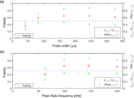
The fidelity measurement results for when the peak Rabi frequency and the pulse width are varied are indicated by the circles in Fig. 4(a) and (b), respectively. In both cases, the fidelity exceeds 0.5 over wide variations in the parameters (0.5 represents the inseparability criterion for two-particle entangled states Sackett et al. (2000)).
VII Discussion of fidelity
There are several possible causes for the fidelity of Dicke state generation being limited to below 0.66. The error consists mainly of that produced when preparing motional Fock states and in the entangling operation with RAP. The causes for the former include insufficient cooling to the motional ground state and an addressing error, and the causes of the latter include phase relaxation processes due to fluctuations in the laser frequency and magnetic field and fluctuations in residual AC Stark shifts due to beam jitter.
To analyze such infidelity factors, the values of and , which respectively reflect the diagonal and off-diagonal density matrix elements, are shown in Fig. 4 (as crosses and asterisks, respectively). Relatively high values are obtained for the former, whereas the latter is limited to below 0.5 over both parameter ranges and it decays with increasing pulse width. Based on these facts, we speculate that the error generated in preparing motional Fock states is not significant, since otherwise we would observe a large reduction in the diagonal matrix elements. We can therefore conclude that the infidelity factors are mainly associated with the entangling operation using RAP. We speculate that phase relaxation processes during the entangling operation mainly cause the infidelity, which is consistent with the decay with increasing pulse width. We expect that the fidelity can be improved by using resonant pulses with improved 729-nm laser linewidths (currently 400 Hz) and using transitions that are less sensitive to the magnetic field, such as –.
VIII Conclusion
We have demonstrated generation of entangled states using an adiabatic method and demonstrated the robustness of the generation process against parameter variations. The method described here can be extended to larger numbers of particles and excitations. Recently, Wieczorek et al. (2009) have shown experimentally that entangled states of inequivalent classes are obtained from six-photon Dicke states via projection measurements on a few of their qubits. In a similar way, large atomic Dicke states generated by methods similar to that described here may be used as entanglement resources for quantum information processing applications.
ACKNOWLEDGEMENTS
This work is supported by MEXT Kakenhi “Quantum Cybernetics” Project and the JSPS through its FIRST Program.
References
- Linington and Vitanov (2008) I. E. Linington and N. V. Vitanov, Phys. Rev. A 77, 010302 (2008).
- Häffner et al. (2005) H. Häffner, W. Hänsel, C. F. Roos, J. Benhelm, D. Chek-al kar, M. Chwalla, T. Körber, U. D. Rapol, M. Riebe, P. O. Schmidt, C. Becher, O. Gühne, W. Dür, and R. Blatt, Nature 438, 643 (2005).
- Leibfried et al. (2005) D. Leibfried, E. Knill, S. Seidelin, J. Britton, R. B. Blakestad, J. Chiaverini, D. B. Hume, W. M. Itano, J. D. Jost, C. Langer, R. Ozeri, R. Reichle, and D. J. Wineland, Nature 438, 639 (2005).
- Blatt and Wineland (2008) R. Blatt and D. Wineland, Nature 453, 1008 (2008).
- Prevedel et al. (2009) R. Prevedel, G. Cronenberg, M. S. Tame, M. Paternostro, P. Walther, M. S. Kim, and A. Zeilinger, Phys. Rev. Lett. 103, 020503 (2009).
- Wieczorek et al. (2009) W. Wieczorek, R. Krischek, N. Kiesel, P. Michelberger, G. Tóth, and H. Weinfurter, Phys. Rev. Lett. 103, 020504 (2009).
- Dicke (1954) R. H. Dicke, Phys. Rev. 93, 99 (1954).
- Eibl et al. (2004) M. Eibl, N. Kiesel, M. Bourennane, C. Kurtsiefer, and H. Weinfurter, Phys. Rev. Lett. 92, 077901 (2004).
- Kiesel et al. (2007) N. Kiesel, C. Schmid, G. Toth, E. Solano, and H. Weinfurter, Phys. Rev. Lett. 98, 063604 (2007).
- Hume et al. (2009) D. B. Hume, C. W. Chou, T. Rosenband, and D. J. Wineland, Phys. Rev. A 80, 052302 (2009).
- Treacy (1968) E. B. Treacy, Phys. Lett. A 27, 421 (1968).
- Vitanov et al. (2001) N. V. Vitanov, T. Halfmann, B. W. Shore, and K. Bergmann, Annu. Rev. Phys. Chem. 52, 763 (2001).
- Wunderlich et al. (2007) C. Wunderlich, T. Hannemann, T. Körber, H. Häffner, C. Roos, W. Hänsel, R. Blatt, and F. Schmidt-Kaler, J. Mod. Opt. 54, 1541 (2007).
- Morris and Shore (1983) J. R. Morris and B. W. Shore, Phys. Rev. A 27, 906 (1983).
- Rangelov et al. (2006) A. A. Rangelov, N. V. Vitanov, and B. W. Shore, Phys. Rev. A 74, 053402 (2006).
- Retzker et al. (2007) A. Retzker, E. Solano, and B. Reznik, Phys. Rev. A 75, 022312 (2007).
- Toyoda et al. (2010) K. Toyoda, S. Haze, R. Yamazaki, and S. Urabe, Phys. Rev. A 81, 032322 (2010).
- Häffner et al. (2003) H. Häffner, S. Gulde, M. Riebe, G. Lancaster, C. Becher, J. Eschner, F. Schmidt-Kaler, and R. Blatt, Phys. Rev. Lett. 90, 143602 (2003).
- Messiah (1961) A. Messiah, Quantum mechanics, Vol. 2 (North-Holland, 1961).
- Sackett et al. (2000) C. A. Sackett, D. Kielpinski, B. E. King, C. Langer, V. Meyer, C. J. Myatt, M. Rowe, Q. A. Turchette, W. M. Itano, D. J. Wineland, and I. C. Monroe, Nature 404, 256 (2000).