Photonic Band Gaps in One-Dimensionally Ordered Cold Atomic Vapors
Abstract
We experimentally investigate the Bragg reflection of light at one-dimensionally ordered atomic structures by using cold atoms trapped in a laser standing wave. By a fine tuning of the periodicity, we reach the regime of multiple reflection due to the refractive index contrast between layers, yielding an unprecedented high reflectance efficiency of 80%. This result is explained by the occurrence of a photonic band gap in such systems, in accordance with previous predictions.
pacs:
37.10.Jk,42.25.Fx,42.70.QsCold atomic vapors can be used as suitable optical media for a number of applications or fundamental studies, in particular, in the fields of nonlinear and quantum optics, but also as complex optical media to study exotic wave transport phenomena, for instance coherent multiple scattering Labeyrie (2008), weak localization Kaiser and Havey (2005) or random lasing Froufe-Pérez et al. (2009). In these examples, an essential property is the disorder inherent to atomic vapors that are simply confined in a magneto-optical trap (MOT).
On the contrary, ordered clouds of cold atoms should exhibit different light-transport properties. The appearance of photonic band gaps (PBGs) has indeed been predicted in one-dimensional lattices Deutsch et al. (1995); Artoni et al. (2005) and recently in three-dimensional, diamond (non-Bravais) lattices Antezza and Castin (2009). The realization of PBGs in cold-atom samples would open the way to study new regimes of light transport in atomic vapors, where correlations and long-range order play a dominant role. The crossover regime, between order and disorder, or correlated disorder, is also a rich subject (see, e.g., Pasienski et al. (2010)), in particular, in relation to Anderson localization Lagendijk et al. (2009).
However, creating efficient photonic structures is hard with cold atoms because these dilute systems have a low refractive index [Fig. 1(a)] and a limited length. So far, efficient Bragg reflection of light has only been obtained with hot vapors, using an electromagnetically induced grating Bajcsy et al. (2003). Previous investigations with cold atoms trapped in optical lattices have reported Bragg scattering with low efficiency. A first series of experiments used three-dimensional quasiresonant lattices Birkl et al. (1995); Weidemüller et al. (1995, 1998), with a lattice geometry that does not create PBGs Antezza and Castin (2009). Efficiencies below 1% were reported. A second series of experiments investigated the 1D case Slama et al. (2005a, b, 2006), where a band gap is expected, but the maximum reflectance was only 5% in total power (30% corrected from the partial overlap between the probe beam and the atomic sample) Slama et al. (2006). The limitations came mainly from the probing angle, which limited the interaction length with the lattice, and losses, i.e., out-of-axis scattering, due to the imaginary part of the atomic polarizability near resonance.
In this Letter, we report the observation of an efficient Bragg reflection at a one-dimensional lattice, reaching the regime of multiple reflections due to the refractive index contrast between layers and an 80% efficiency in total power. This high efficiency is obtained by (1) using a small-diameter probe beam and a small probing angle to optimize the overlap with the atomic grating, and (2) adjusting the periodicity of the lattice so that the Bragg condition is fulfilled off the atomic resonance, thus strongly reducing the losses. Our experimental observations are explained by the appearance of a PBG, which we show to be robust against the system imperfections (finite length, varying density).
The experiment starts with a vapor-loaded MOT of 87Rb containing about atoms. A dipole trap is generated by a homemade titanium-sapphire laser, whose available power is W and whose wavelength is tunable. The beam is focussed on a waist ( radius) m at the MOT position (Rayleigh length m). A 1D optical lattice is made by retroreflecting the beam, thus generating a structure whose periodicity is .
After stages of compression and molasses, the MOT is switched off and a waiting time of a few ms allows the untrapped atoms to fall down. Then, we can characterize the trapped sample with absorption imaging or acquire transmission and reflection spectra. Typical numbers for the trapped atoms are atoms distributed over a length mm ( layers). The temperature, K, is related to the potential depth by a constant factor . The transverse extension of the cloud is then m and the thickness of each layer along the lattice axis is nm (rms radii in the harmonic approximation).
To acquire spectra, we shine a weak and small (waist m), linearly polarized probe beam onto the lattice under an angle of incidence . The angle is small enough so that the probe interacts with the lattice over its entire length and that the reflection is specular Slama et al. (2005b). The transmitted and reflected beams are then recorded with avalanche photodiodes. The probe frequency is swept in the vicinity of the atomic resonance ( closed transition of the D2 line, nm, linewidth MHz) by using an acousto-optical modulator in double-pass configuration. The other hyperfine levels are far enough to be negligible. The presented data are the result of an average of typically 100 cycles (the duration of each cycle is s).
Reflection occurs in the vicinity of a Bragg condition: the difference between the incident probe wavevector and the reflected wavevector must equal the lattice vector, i.e. , where is the probe wavevector in vacuum, is the real part of the average refractive index of the medium, is the probe detuning from the atomic resonance, and is the lattice vector foo (a).
Experimentally, we keep the angle constant and adjust the Bragg condition by tuning the wavelength of the lattice beam. It is thus meaningful to rewrite the Bragg condition in the following form,
| (1) |
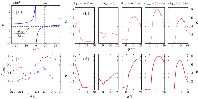
where is the shift from the “geometric” (with ) Bragg condition . With , nm. Then, for a given lattice wavelength, the Bragg condition is fulfilled for probe detunings given by Eq. (1), see Fig. 1(a). There are in general two such frequencies, but one is almost on resonance, where losses prevent any efficient reflection. The other Bragg frequency [ in Fig. 1(a)] may be farther from resonance and can be tuned in order to search for an optimum.
Such an experiment is reported in Fig. 1(b), which shows a set of spectra for different . As expected from Eq. (1), the spectra display a strong asymmetry, which evolves as the lattice wavelength is changed, the maximal efficiency going from one side of the resonance to the other side while changes its sign. One can also clearly observe an optimum value of for reaching high efficiencies, namely for nm with our best atom number [Fig. 1(c)]. Note that for each , we adjust the power accordingly to keep constant the potential depth and subsequently the atom number and temperature.
The existence of an optimum can easily be understood by considering the limiting cases. When is very small, the Bragg condition is fulfilled where the refractive index is almost one, in virtue of Eq. (1), very far from resonance, leading to a very small index contrast in the periodic structure and thus to an inefficient reflection. In the opposite limit, when is large, the Bragg condition is fulfilled near , where losses, due to the imaginary part of the atomic polarizability, are large and play a detrimental role. Ultimately, if is too large for the given averaged atomic density , the Bragg condition cannot be fulfilled at all. The optimum depends on the average density : a larger density allows us to increase , and thus the index contrast, without shifting the Bragg frequency towards resonance, i.e. without increasing losses. This is illustrated in Fig. 1(c), which shows that the optimum is larger with more atoms.
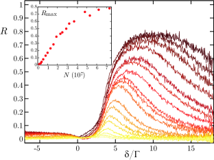
We have also studied the reflection spectrum as a function of the atom number for a given . In order to vary the atom number while keeping the lattice length constant, we have changed the waiting time in the lattice, before the spectra acquisition, from 5 ms to 400 ms, thus varying atom losses. The result is reported in Fig. 2. As expected from Eq. (1), we observe a shift farther from resonance together with a broadening for increasing densities. The evolution of the maximum reflectance as a function of the atom number (inset of Fig. 2) reveals that we almost reach saturation.
With such a high efficiency, it is natural to ask whether a photonic band gap occurs in our system and is responsible for the high reflectance. It is well-known that periodic 1D systems give rise to PBGs for any nonzero index modulation Joannopoulos et al. (2008), so that no distinction is usually made between a 1D PBG and a Bragg reflector. However this is true only for infinite, lossless, and perfectly periodic media. As already noted, the atomic polarizability is complex so that our system has losses, and it is of course finite. Moreover, the lattice is not perfectly homogeneous but has a smooth density variation, so that the periodicity is not perfect. The situation is thus more intricate and deserves a careful analysis.
We can get a first insight with orders-of-magnitude estimations. A Bragg reflector made of repeated pairs of dielectric layers gives rise, in the stop band, to an evanescent wave whose penetration length (or Bragg length) is given by , where is the refractive index difference between the two materials Brovelli and Keller (1995). By approximating the Gaussian atomic distribution in each well by a single layer of constant density with the same rms width and using Eq. (1), the index contrast is . In our experiment, the maximum reflection is obtained for nm and we have , which gives a penetration length mm, sensibly smaller than our optical lattice (mm), so that we are indeed in the multiple-reflection regime. The effect of losses can also be evaluated by comparing the corresponding attenuation length to . Given our estimated averaged density cm-3 and the detuning determined by the Bragg condition (1), we estimate , where is the scattering cross section, which gives mm, also much larger than . Thus, this simple calculation confirms that our system fulfills the conditions , which are necessary for the appearance of a band gap. A number of effects are however not taken into account, in particular the actual density distribution along the lattice, so that a more precise modeling is still valuable.
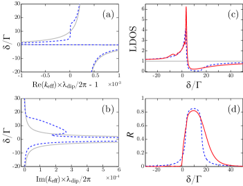
We use the transfer matrix formalism to simulate the wave propagation in our system, and we refer to Deutsch et al. (1995); Artoni et al. (2005); Slama et al. (2006) for detailed descriptions in similar contexts. From the transfer matrix of one single period, which takes into account the Gaussian atomic distribution in each well Slama et al. (2006), we draw the dispersion relations of the medium (effective wavevector vs ), valid in the limit of an infinitely long lattice (Bloch theorem). These are shown in Fig. 3(a,b), for the typical parameters of the experiment cm-3, and nm. The imaginary part of is composed of one Lorentzian of width centered on resonance, which corresponds to losses, and a supplementary part, leading to an evanescent wave, corresponding to a band gap [Fig. 3(b)]. In the same frequency range, the real part of has a reduced variation with [Fig. 3(a)], corresponding to a reduced density of states (DOS) . This last formula is however not always valid, especially in anomalous dispersive media, and we use the method of Boedecker and Henkel (2003) to compute the normalized local DOS in the middle of the lattice. By using the complex reflection coefficients , of the two surrounding, finite or infinite Deutsch et al. (1995) semilattices, we obtain
| (2) |
The result, shown in Fig. 3(c), exhibits clearly the band gap, with a strong reduction of the normalized local DOS, which reaches at minimum 6% for an infinite lattice. The corresponding reflection spectrum reaches 85% [Fig. 3(d)]. In both cases, the limitation (for achieving high reflectance or low DOS) is the remaining losses.
To take into account the limited length of the sample and its actual, smooth density distribution along the lattice axis, that we characterized by absorption imaging, we compute the reflection spectra through the whole structure by multiplying elementary transfer matrices computed with the corresponding local density. The local DOS then exhibits a smaller reduction, reaching at minimum 23%, but the maximum reflectance is almost as high as in the infinite limit, reaching 82% [Fig. 3(c,d)].
Finally, to simulate our experimental spectra precisely, we must also take into account the trapping-induced inhomogeneous light shift and the finite transverse size. Indeed, we only considered so far infinitely extended layers, which is a crude approximation, the atom cloud having an rms width of m. The probe beam, having also a finite size, probes a distribution of local density, which induces an inhomogeneous broadening of the spectra. There is in fact a tradeoff for the probe beam size: a small beam allows us to probe a well-defined and maximum density, but since the reflection is very sensitive to the angle of incidence, the probe divergence induces also an inhomogeneous broadening. Experimentally, we have tried several probe sizes and obtained the maximum reflectance with m. To simulate these effects we averaged many spectra over Gaussian distributions of incident angles and densities corresponding, respectively, to the probe divergence and atomic density distribution along the transverse directions. We obtain the spectra of Fig. 1(d), in good agreement with the experiment foo (b).
To summarize, we have studied experimentally the Bragg reflection of light at a one-dimensional atomic quasiperiodic structure in the regime of multiple reflection, demonstrating a high efficiency, thanks to a fine tuning of the lattice periodicity. Then, motivated by the modeling of our system, we have investigated the effects of the finite length and of the smooth density variation along the lattice on the appearance of a band gap and its quality. These imperfections, inherent to cold-atom systems, do not destroy the band gap which, even if the DOS reduction is not dramatic, still substantially modifies the transport properties of light, as demonstrated by the observed high reflectance.
Improving further the quality of the PBG requires reducing the losses by creating the band gap farther from resonance, which could be done by increasing the density or the lattice length, for example with a larger initial MOT. Another fascinating possibility is to tailor the atomic polarizability to remove its absorptive part, while enhancing the refractive index, following the ideas of Scully (1991); Fleischhauer et al. (1992). Finally, the extension to more evolved lattice geometries, for example with bichromatic lattices Rist et al. (2009) and to three dimensions Antezza and Castin (2009), has been proposed recently. This last case is of course the most appealing since a 3D band gap would profoundly modify the atom-light interaction Yablonovitch (1987); Lodahl et al. (2004).
We thank J.-F. Schaff and N. Mercadier for the computer-control program. We acknowledge support from the Alexander von Humboldt foundation, the DFG and the REA (program COSCALI, No. PIRSES-GA-2010-268717).
References
- Labeyrie (2008) G. Labeyrie, Mod. Phys. Lett. B 22, 73 (2008).
- Kaiser and Havey (2005) R. Kaiser and M. Havey, Opt. Photonics News 16, 38 (2005).
- Froufe-Pérez et al. (2009) L. Froufe-Pérez, W. Guerin, R. Carminati, and R. Kaiser, Phys. Rev. Lett. 102, 173903 (2009); W. Guerin et al., J. Opt. 12, 024002 (2010).
- Deutsch et al. (1995) I. H. Deutsch, R. J. C Spreeuw, S. L. Rolston, and W. D. Phillips, Phys. Rev. A 52, 1394 (1995).
- Artoni et al. (2005) M. Artoni, G. La Rocca, and F. Bassani, Phys. Rev. E 72, 046604 (2005).
- Antezza and Castin (2009) M. Antezza and Y. Castin, Phys. Rev. A 80, 013816 (2009).
- Pasienski et al. (2010) M. Pasienski, D. McKay, M. White, and B. DeMarco, Nature Phys. 6, 677 (2010).
- Lagendijk et al. (2009) A. Lagendijk, B. van Tiggelen, and D. S. Wiersma, Phys. Today 62, No 8, 24 (2009); A. Aspect and M. Inguscio, Phys. Today 62, No 8, 30 (2009).
- Bajcsy et al. (2003) M. Bajcsy, A. S. Zibrov, and M. D. Lukin, Nature (London) 426, 638 (2003).
- Birkl et al. (1995) G. Birkl et al., Phys. Rev. Lett. 75, 2823 (1995).
- Weidemüller et al. (1995) M. Weidemüller et al., Phys. Rev. Lett. 75, 4583 (1995).
- Weidemüller et al. (1998) M. Weidemüller, A. Görlitz, T. W. Hänsch, and A. Hemmerich, Phys. Rev. A 58, 4647 (1998).
- Slama et al. (2005a) S. Slama et al., Phys. Rev. Lett. 94, 193901 (2005a).
- Slama et al. (2005b) S. Slama et al., Phys. Rev. A 72, 031402(R) (2005b).
- Slama et al. (2006) S. Slama et al., Phys. Rev. A 73, 023424 (2006).
- foo (a) Note that contrary to the original situation considered in Deutsch et al. (1995), the refractive index for the lattice beam is negligible.
- Joannopoulos et al. (2008) J. D. Joannopoulos et al., Photonic crystals: molding the flow of light (Princeton University, Princeton, NJ, 2008), 2nd ed..
- Brovelli and Keller (1995) L. R. Brovelli and U. Keller, Opt. Commun. 116, 343 (1995).
- Boedecker and Henkel (2003) G. Boedecker and C. Henkel, Opt. Express 11, 1590 (2003).
- foo (b) The lower efficiency for might be due to heating induced by spontaneous emission, the dipole trap being closer to resonance.
- Scully (1991) M. O. Scully, Phys. Rev. Lett. 67, 1855 (1991).
- Fleischhauer et al. (1992) M. Fleischhauer et al., Phys. Rev. A 46, 1468 (1992).
- Rist et al. (2009) S. Rist, P. Vignolo, and G. Morigi, Phys. Rev. A 79, 053822 (2009).
- Yablonovitch (1987) E. Yablonovitch, Phys. Rev. Lett. 58, 2059 (1987).
- Lodahl et al. (2004) P. Lodahl et al., Nature (London) 430, 654 (2004).