Disk Formation in Magnetized Clouds Enabled by the Hall Effect
Abstract
Stars form in dense cores of molecular clouds that are observed to be significantly magnetized. A dynamically important magnetic field presents a significant obstacle to the formation of protostellar disks. Recent studies have shown that magnetic braking is strong enough to suppress the formation of rotationally supported disks in the ideal MHD limit. Whether non-ideal MHD effects can enable disk formation remains unsettled. We carry out a first study on how disk formation in magnetic clouds is modified by the Hall effect, the least explored of the three non-ideal MHD effects in star formation (the other two being ambipolar diffusion and Ohmic dissipation). For illustrative purposes, we consider a simplified problem of a non-self-gravitating, magnetized envelope collapsing onto a central protostar of fixed mass. We find that the Hall effect can spin up the inner part of the collapsing flow to Keplerian speed, producing a rotationally supported disk. The disk is generated through a Hall-induced magnetic torque. Disk formation occurs even when the envelope is initially non-rotating, provided that the Hall coefficient is large enough. When the magnetic field orientation is flipped, the direction of disk rotation is reversed as well. The implication is that the Hall effect can in principle produce both regularly rotating and counter-rotating disks around protostars. We conclude that the Hall effect is an important factor to consider in studying the angular momentum evolution of magnetized star formation in general and disk formation in particular.
1 Introduction
Disks are an integral part of star formation; they are the birthplace of planets. How they form is a long-standing, unresolved problem. A major difficulty is that their formation is greatly affected by magnetic braking, which has been hard to quantify until recently.
There is now increasing theoretical evidence that magnetic braking may suppress the formation of rotationally supported disks (RSDs hereafter) in dense cores magnetized to a realistic level, with dimensionless mass-to-flux ratios of a few to several (Troland & Crutcher, 2008). Allen et al. (2003) first demonstrated through 2D (axisymmetric) simulations that RSDs are suppressed by a moderately strong magnetic field in the ideal MHD limit. Galli et al. (2006) showed analytically that the disk suppression is due to the formation of a split magnetic monopole, which is an unavoidable consequence of flux freezing. The efficient disk braking was confirmed numerically by Mellon & Li (2008) and Hennebelle & Fromang (2008) (see, however, Machida et al. 2010 and Hennebelle & Ciardi 2009 for a different view, and Li et al. 2011 for a more detailed discussion). The ideal MHD approximation must break down in order for RSD to form.
Two non-ideal MHD effects have already been explored in the context of disk formation: ambipolar diffusion and Ohmic dissipation. Krasnopolsky & Königl (2002) found that ambipolar diffusion tends to make disk braking more efficient, because it enables the magnetic flux that would have gone into the central protostellar object (and form a split monopole) in the ideal MHD limit to pile up at small radii outside of the object instead, making the region strongly magnetized (Li & McKee 1996, Ciolek & Königl 1998, Contopoulos et al. 1998). Mellon & Li (2009) showed that the enhanced braking is strong enough to suppress the formation of RSDs for realistic core conditions. The effect of Ohmic dissipation was examined by several groups, starting with Shu et al. (2006). They suggested that enhanced resistivity (well above the classical value) is needed for Ohmic dissipation to weaken the magnetic braking enough to form a relatively large RSD of tens of AUs or more. The suggestion was confirmed by Krasnopolsky et al. (2010; KLS10 hereafter), although Machida et al. (2010) were apparently able to form RSDs using the classical resistivity computed by Nakano et al. (2002) (see also Dapp & Basu 2010). In any case, a third non-ideal MHD effect, the Hall effect, has not been explored in the context of disk formation (see, however, the independent work of C. Braiding in her unpublished PhD thesis); it is the focus of this paper.
Our goal is to determine whether the Hall effect by itself can enable an RSD to form in the presence of a relatively strong magnetic field and, if yes, to estimate the magnitude of Hall coefficient needed for RSD formation. We find that the Hall effect can actively spin up the inner part of the protostellar collapsing flow, potentially to Keplerian speed, unlike the other two non-ideal MHD effects. The combined effect of all these three non-ideal MHD terms on disk formation will be explored in another investigation (Li et al. 2011; LKS11 hereafter).
2 Problem Setup
We adopt the same problem setup as in KLS10, where we consider the collapse onto a star of of a rotating envelope that is uniformly magnetized initially. In the absence of any non-ideal MHD effect, the magnetic field would prevent an RSD from forming through magnetic braking. The Hall effect changes the evolution of the magnetic field (and thus the braking efficiency) through the induction equation:
| (1) |
where is a coefficient of the Hall effect which, for simplicity, we will assume to be spatially constant. The MHD equations are solved using ZeusTW, a 3D non-ideal MHD code based on Zeus3D (Clarke, Norman, & Fiedler, 1994). We treat the Hall term in the induction equation using an explicit method based on Sano & Stone (2002) and Huba (2003), which includes subcycling to speed up the computation.
As in KLS10, we adopt a spherical polar coordinate system (, , ), and fill the computation domain with an isothermal gas of sound speed between and . A uniform density is assumed, so that the total envelope mass is . For the initial rotation, we adopt the following prescription:
| (2) |
where is the cylindrical radius, and and are chosen. With this setup, an RSD of in radius is produced at a representative time of in the absence of any magnetic field (see Fig. 1 of KLS10). It is completely destroyed by a moderately strong initial magnetic field of in the ideal MHD limit (see Fig. 2 of KLS10). Whether the RSD can be restored by the Hall effect is the question that we seek to address.
3 Result
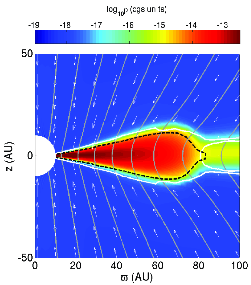
We consider first a model where the initial magnetic field is parallel to the rotation axis (Model PARA in Table 1) and the coefficient in the Lorentz-Heaviside units convenient to use with the Zeus family of codes, corresponding to in Gaussian CGS units (). An RSD is able to form in this case, as illustrated Fig. 1, which plots a color map of density distribution, velocity field and magnetic field lines in the meridian plane (left panel), and the infall and rotation speeds on the equator (right panel), at a representative time . The RSD shows up clearly on the color map as the flattened high density region of about in radius. It has an infall speed that is close to zero and a rotation speed that is Keplerian. The Hall effect has clearly enabled an RSD to form, although it is not by weakening the magnetic braking that would have suppressed the RSD formation in the ideal MHD limit, unlike the case of Ohmic dissipation (KLS10). The RSD is formed because the inner part of the collapsing flow is actively spun up by the Hall effect. A strong support for Hall spin-up as the cause for the RSD formation comes from a second simulation where we flip the sign of the initial magnetic field direction (Model ANTI), so that the field is anti-parallel, rather than parallel, to the rotation axis. In this case, an RSD disk is again formed, but it rotates in a direction opposite to the initial rotation, as shown in Fig. 2. The reversal of the disk rotation direction means that the Hall effect does not merely weaken the magnetic braking so that enough of the original angular momentum is retained for RSD formation.
| Model | Q (cgs units) | () | Rotation | RSD? |
|---|---|---|---|---|
| PARA | 35.4 | yes | yes | |
| ANTI | - 35.4 | yes | yes | |
| NoROT | 35.4 | no | yes | |
| LoB | 10.6 | no | yes | |
| LoQ | 35.4 | no | yes | |
| LoQ1 | 35.4 | no | yes | |
| LoQ2 | 35.4 | no | no |


The reason that the disk rotation direction is reversed when the magnetic field direction is flipped is the following (see Wardle & Königl 1993 for a similar discussion in the context of disk-wind launching). From the induction equation (1), it is easy to see that the Hall effect forces the field lines to move with a velocity
| (3) |
where is the current density. The pinching of the poloidal magnetic field near the equatorial region produces a strong toroidal current, , which changes sign as the poloidal field direction is flipped. The toroidal current of different signs causes the field lines to wind up toroidally in opposite directions, giving rise to magnetic torques of opposite sense. In the case where the initial field line is parallel to the rotation axis, is positive, giving rise to a toroidal field-line speed that is negative (assuming that the Hall coefficient is positive, which is not necessarily true, see, e.g., Wardle & Ng 1999 and LKS11; changes sign if is negative). Since the toroidal current is the strongest on the equator, the field line is twisted backward most on the equator and less so above and below the equatorial plane. The differential twist forces the field line to bend in the positive azimuthal direction, creating a torque that spins up the material near the equatorial plane in the same direction as the initial rotation. This explains why the RSD in the field-rotation aligned case rotates in the same sense as the initial rotation. When the initial field direction is flipped, the toroidal current (and thus ) changes sign, forcing the field lines to bend in the negative azimuthal direction. The resulting negative torque not only overcame the initial positive rotation but also produced a counter-rotating RSD in the anti-aligned case.
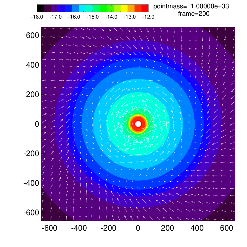
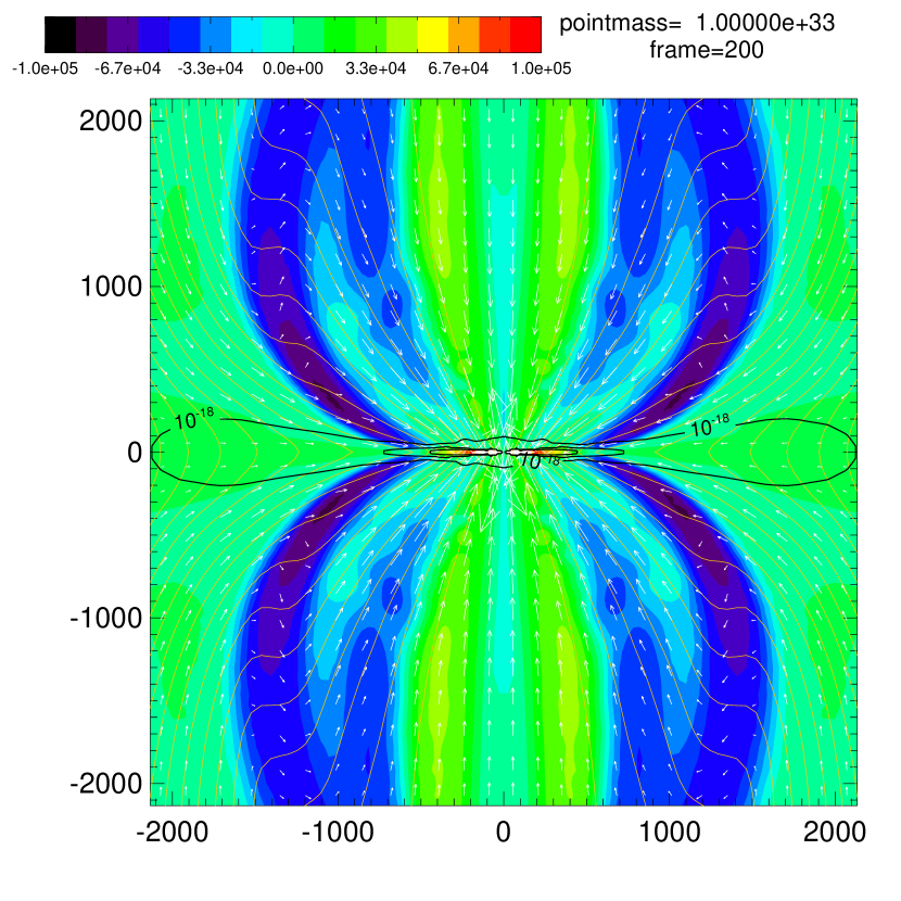
The Hall spin-up is even more unambiguous in Model NoROT where the envelope is initially non-rotating; any subsequent rotation must be due to the Hall effect. The right panel of Fig. 3 shows that an RSD is again formed in this case, with the rotation speed approaching the Keplerian speed and the infall speed dropping close to zero inside a radius . Since the envelope is initially non-rotating, the spin of the RSD must be balanced by material rotating in the opposite direction. The left panel of Fig. 3 demonstrates that this is indeed the case. It shows that, outside the equatorial plane, materials of positive and negative angular momentum occupy alternating shells. Inside a radius of , the angular momentum is positive, dominated by the (small) RSD and highly flattened pseudodisk outside RSD (see the isodensity contours). At larger distances, the angular momentum becomes negative, dominated by the outermost counter-rotating shell shown in the Fig. 3. The total positive angular momentum () does not exactly balance out the total negative angular momentum (), however, indicating some angular momentum is transported out of the simulation box, presumably through torsional Alfvén waves. Note that the Hall effect modifies the envelope rotation well beyond the -scale RSD. We have verified that when the initial magnetic field direction is flipped, the direction of the Hall-induced rotation is reversed.

Besides torquing up the envelope in the toroidal direction, the Hall effect also enables the magnetic field lines to diffuse out radially. In the absence of any radial diffusion, the field lines would be pulled by the accreting material into a split magnetic monopole, which is not present in any of the simulations discussed so far. Indeed, at small radii where the Hall spin-up is most efficient, the inward advection of poloidal magnetic field is almost exactly balanced by the outward magnetic diffusion enabled by the Hall effect. This balance is illustrated in the right panel of Fig. 3, which shows that, inside a radius , the radial component of the Hall-induced field line drift velocity on the equator has almost the same magnitude as the infall speed but with an opposite sign. The radial magnetic diffusion allows material to fall inward without dragging field lines along with it. The situation is similar in the azimuthal direction, where the Hall-induced field line drift speed and the fluid rotation speed are nearly identical in magnitude but opposite in sign. The azimuthal Hall-induced drift prevents the field lines from being wound up continuously by rotation. The required toroidal current is provided by the bending of the field lines inside the disk (see left panel of Fig. 1; contrast with the unbent field lines in Fig. 7 of KLS10).
An interesting feature of the envelope collapse is that the infall speed of the equatorial material remains well below the free-fall speed. The equatorial collapse is slowed down three times (see right panel of Fig. 3), for different reasons. The first slowdown near corresponds to the edge of the magnetic bubble inflated by field twisting (outside the region shown in the right panel of Fig. 3), where a magnetic barrier forces the collapsing material over a large solid angle into a narrow equatorial channel (see Fig. 2 of Mellon & Li 2008 and associated discussion). The second slowdown occurs near (or about ), inside which the accreted magnetic flux is left behind due to Hall diffusion. It is similar in origin to the ambipolar diffusion-induced accretion shock first discussed in Li & McKee (1996; a similar behavior is also present in the Ohmic dissipation-only case, LKS11). The increase in the poloidal magnetic field strength enabled by Hall diffusion in the radial direction makes it easier to spin up the equatorial material through the Hall-induced magnetic torque. The third slowdown near is obviously due to centrifugal effect, since an RSD is formed interior to it.
To check how robust the above results from Model NoROT are, we did a number of variants of the model. First, we reduced the initial field strength to of its original value, from to (Model LoB). The result is shown in the left panel of Fig. 4 (see dashed lines). An RSD is again formed at the representative time , despite the reduced initial field strength. It is somewhat smaller than that in the original case, which is to be expected since the Hall spin-up depends on current density, which increases with field strength. Another difference is that the infall speed outside the RSD is higher in the weaker field case, because the magnetic forces that oppose gravity are weaker. Second, we reduced the coefficient by a factor of 10, from to in Gaussian cgs units (Model LoQ). An RSD is still formed at . With a radius of or , it is much smaller than the RSD in the original Model NoROT. If we reduce the value of by another factor of 3 (to , Model LoQ1), an RSD still forms, but it extends barely outside the inner boundary of our computation domain, which has a radius of . When the value of Q is reduced further to (Model LoQ2), the RSD disappears. We therefore take as a rough estimate for the value of needed for the Hall-enabled formation of a relatively large RSD of tens of AUs or more in size.


We have verified that the RSD formed in Model NoROT is little affected when the classical Ohmic resistivity used in KLS10 (based on Nakano et al. 2002) is included. An enhanced resistivity can, however, reduce the size of the RSD significantly. Experimentation shows that it suppresses the Hall-enabled RSD formation in Model NoROT altogether when the resistivity is on the order of or larger. The negative effect of the resistivity on the Hall spin-up is not surprising, since it reduces the electric current density in general, and the toroidal current density in particular; the latter is the driver of the spin-up through the Hall-induced magnetic torque.
How does the critical value of estimated for RSD formation compare with the microscopic values of expected in realistic dense cores? In a separate study (LKS11), we have computed the values of as a function of hydrogen number density ), based on a simple prescription for the magnetic field strength as a function of density (Nakano et al., 2002) and a simplified chemical network for charge densities (Nishi et al., 1991), including two extreme grain size distributions: (1) the standard MRN power-law distribution (Mathis et al. 1977; appropriate for diffuse interstellar clouds), and (2) grains of single, large size of . These two cases should bracket the situation in dense molecular cloud cores, where some grain growth is expected. As can be seen from the right panel of Fig. 4, although the microscopic values of can be larger than the critical value at relatively low densities, they are smaller than by about an order of magnitude at densities of order (or higher) that are crucial for RSD formation (see the left panel of Fig. 1).
4 Conclusion and Discussion
We have studied the collapse of a non-self-gravitating rotating, magnetized envelope onto a central stellar object of fixed mass to illustrate the influence of the Hall effect on disk formation. In this idealized problem, the formation of a rotationally supported disk (RSD) is completely suppressed by magnetic braking in the ideal MHD limit. Including a Hall term with a coefficient in the induction equation enables an RSD of radius to form. The RSD is formed not because the Hall effect has reduced the efficiency of the magnetic braking. Rather, it is produced because the Hall effect actively spins up the inner part of the equatorial material to Keplerian speed. The spin-up comes about because the collapsing envelope drags the magnetic field into a highly pinched configuration near the equator, producing a large toroidal electric current density, which forces the field lines to rotate differentially due to the Hall effect. The resulting twist of field lines yields the magnetic torque that spins up the equatorial material, even in the absence of any initial rotation. The spin-up is most effective in the inner part of the accretion flow where radial Hall diffusion enables the magnetic flux that would have been dragged into the central object by the accreted material in the ideal MHD limit to stay behind; the resulting pileup of magnetic flux at small radii is similar to the cases with either ambipolar diffusion or Ohmic dissipation. When the field direction is flipped, the Hall-induced magnetic torque changes direction as well. An implication is that the direction of the angular momentum of the material close to a protostar, including RSD, may depend more on the magnetic field orientation than on the initial rotation of the dense core that the star is formed out of, at least in principle.
In practice, it is uncertain whether the Hall-induced magnetic torque can produce a sizable RSD or not. First, the value of the coefficient required to produce an RSD of tens of AUs in size in our idealized model appears to be larger than the microscopic values expected in dense cores, by roughly an order of magnitude. Whether the coefficient can be enhanced somehow, perhaps through anomalous processes, is unclear. More importantly, the Hall effect is only one of the non-ideal MHD effects that are present in the lightly ionized, magnetized, dense cores. It can be dominated by ambipolar diffusion at low densities and by Ohmic dissipation at high densities. It will be interesting to explore the interplay of all these three non-ideal MHD effects and how they affect the collapse of dense cores and the formation of protostellar disks. Nevertheless, we have demonstrated that the Hall effect is unique among the non-ideal effects in its ability to actively spin up a magnetized collapsing flow, potentially to Keplerian speed, providing a new mechanism for disk formation.
References
- Allen et al. (2003) Allen, A., Li, Z.-Y., & Shu, F. H. 2003, ApJ, 599, 363
- C. Braiding (2011) Braiding, C. 2011, unpublished PhD thesis, Macquarie University
- Ciolek & Königl (1998) Ciolek, G. E., & Königl, A. 1998, ApJ, 504, 257
- Clarke, Norman, & Fiedler (1994) Clarke, D. A., Norman, M. L., & Fiedler, R. A. 1994, ZEUS-3D User Manual (Tech. Rep. 015; Urbana-Champaign: National Center for Supercomputing Applications)
- Contopoulos et al. (1998) Contopoulos, I., Ciolek, G. E., & Königl, A. 1998, ApJ, 504, 247
- Dapp & Basu (2010) Dapp, W. B., & Basu, S. 2010, A&A, 521, 56
- Galli et al. (2006) Galli, D., Lizano, S., Shu, F. H., & Allen, A. 2006, ApJ, 647, 374
- Hennebelle & Fromang (2008) Hennebelle, P., & Fromang, S. 2008, A&A, 477, 9
- Hennebelle & Ciardi (2009) Hennebelle, P., & Ciardi A. 2009, A&A, 506, L29
- Huba (2003) Huba, J. D. 2003, in Space Plasma Simulation, ed. J. Büchner, C. Dum, & M. Scholer, Lecture Notes in Physics, vol. 615 (Berlin: Springer), 166
- Krasnopolsky & Königl (2002) Krasnopolsky, R., & Königl, A. 2002, ApJ, 580, 987
- Krasnopolsky et al. (2010) Krasnopolsky, R., Li, Z.-Y., & Shang, H. 2010, ApJ, 716, 1541 (KLS10)
- Li et al. (2011) Li, Z.-Y., Krasnopolsky, R., & Shang, H. 2011, ApJ, to be submitted (LKS11)
- Li & McKee (1996) Li, Z.-Y., & McKee, C. F. 1996, ApJ, 464, 373
- Machida et al. (2010) Machida, M. N., Inutsuka, S., & Matsumoto, T. 2010, arXiv:1009.2140
- Mathis et al. (1977) Mathis, J. S., Rumpl, W., & Nordsieck, K. H. 1977, ApJ, 217, 425
- Mellon & Li (2008) Mellon, R. R., & Li, Z.-Y. 2008, ApJ, 681, 1356
- Mellon & Li (2009) Mellon, R. R., & Li, Z.-Y. 2009, ApJ, 698, 922
- Nakano et al. (2002) Nakano, T., Nishi, R., & Umebayashi, T. 2002, ApJ, 573, 199
- Nishi et al. (1991) Nishi, R., Nakano, T., & Umebayashi, T. 1991, ApJ, 368, 181
- Sano & Stone (2002) Sano, T., & Stone, J. M. 2002, ApJ, 570, 314
- Shu et al. (2006) Shu, F. H., Galli, D., Lizano, S., & Cai, M. 2006, ApJ, 647, 382
- Troland & Crutcher (2008) Troland, T. H., & Crutcher, R. M. 2008, ApJ, 680, 457
- Wardle & Königl (1993) Wardle, M., & Königl, A. 1993, ApJ, 410, 218
- Wardle & Ng (1999) Wardle, M., & Ng, C. 1999, MNRAS, 303, 246