Enhanced Quantum Communication via Optical Refocusing
Abstract
We consider the problem of quantum communication mediated by an optical refocusing system, which is schematized as a thin lens with a finite pupil. This model captures the basic features of all those situations in which a signal is either refocused by a repeater for long distance communication, or it is focused on a detector prior to the information decoding process. Introducing a general method for linear optical systems, we compute the communication capacity of the refocusing apparatus. Although the finite extension of the pupil may cause loss of information, we show that the presence of the refocusing system can substantially enhance the rate of reliable communication with respect to the free-space propagation.
pacs:
03.67.Hk, 42.50.Ex, 42.30.-dAlthough quantum information is more commonly described in terms of discrete variables (e.g., qubits), information is most naturally encoded in the electromagnetic field (EMF) via a continuous variable representation CVs . All the fundamental quantum information tools and protocols, from teleportation to quantum key distribution, have been demonstrated for such encoding tools . Here we consider the problem of quantum communication QOchannel ; Shapiro ; YUENSH and compute the maximum rate at which information can be reliably transmitted through EMF signals which propagate along an optical communication line under refocusing conditions. Even though we explicitly consider classical information Ccapacity , our results are immediately extensible to the case of quantum information Qcapacity .
In the classical domain, the ultimate limits for communication via continuous variable encodings were provided by the seminal work of C. E. Shannon on Gaussian channels Shannon . In the quantum domain such channels are replaced by the so called Bosonic Gaussian Channels (BGC), which describe the propagation of the EMF in linear media HOLWER . Their structure is notably rich Gchannels , and up to date a full information-theoretical characterization has been achieved only for certain special subclasses broadband ; Wolf . These results have been applied to compute the maximal rates of reliable communication via attenuating media, as optical fibers, wave-guides, and via free-space propagation freespace ; Shapiro ; wave .
Here we move further in this direction by characterizing the propagation of the EMF through a linear optical system, which induces refocusing of the transmitted signals. For the sake of simplicity, we model this apparatus as a thin lens with finite pupil placed between the sender of the message and the receiver under focusing conditions. Notwithstanding its relatively simple structure, this model captures the basic features of all those situations in which a signal is either refocused by a suitable repeater to allow long distance communication, e.g., by means of parabolic antenna for satellite communication satellite , or it is focused on a detector prior to the information decoding process. The latter include, e.g., the settings in which the EMF is used for the readout process and those in which an optical system is used to interface light and matter lenses .
The quantum description of the scattering of the signal by the optical system is derived by consistently applying the canonical quantization rules, see Shapiro and Refs. therein. Within this framework we show that while the finiteness of the pupil limits the channel bandwidth telegraph , the rate of information transmission is always enhanced by the presence of the lens. It turns out that the resulting improvement with respect to the free-space communication scheme may be particularly advantageous when only few photons per mode are employed in the information transmission — a configuration which is close to the operative regimes of the long distance free-space communication protocols realized so far longd .
The optical system.– Consider a linear optical system with a set of transmitter modes, labelled by , and receiver modes, labelled by . In the case of RF or microwave communication, for example, the transmitter and receiver could be antennae. For optical communication, the transmitter could be a laser coupled to a telescope, and the receiver could be a telescope coupled to a CCD array. Transmitter and receiver modes typically have both spatial characteristics determined by the optical characteristics of the transmitter and receiver, and temporal characteristics, determined by the frequency and bandwidth of the transmitted radiation. The transmittivity matrix gives the fraction of light from the ’th transmitter mode that is received at the ’th receiver mode. We would like to determine the maximum amount of information that can be sent from transmitter to receiver for fixed total input power.
Let us consider the purely lossy case, in which noise from the environment is negligible. This is the case, for example, for free-space optical communication in a thermal background. The addition of noise will be considered below. If the loss is and there are parallel channels with total average photon number , then the communication capacity, measured in nats, is broadband
| (1) |
where , and the capacity is attained by sending coherent states down the channel.
In our case, we have a single multimode lossy channel with transfer matrix , which mixes the input modes together. This channel can be transformed into a set of parallel channels by using the singular value decomposition. The singular value decomposition states that any matrix can be written as , where , are unitary matrices, and is a nonnegative diagonal matrix. We can write in components as . The are the singular values of the transfer matrix. The singular value decomposition shows that any multimode lossy channel can be decomposed into parallel lossy channels with input modes corresponding to the rows of , output modes corresponding to the columns of , and loss factors corresponding to the singular values . The singular value input modes can now be quantized using annihilation and creation operators : . Similarly, the output modes can be quantized using operators : . To preserve the canonical quantization relationships, each input-output pair is coupled to a loss mode with operators , . We see that the singular value decomposition of the multimode lossy quantum channel renders the channel completely equivalent to a set of parallel lossy quantum channels with loss factors .
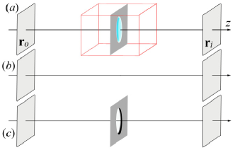
We consider the case of monochromatic light propagating along an optical axis. Following Shapiro ; YUENSH the input and output signals are identified by the transverse field modes at two planes orthogonal to the optical axis [the object plane and image plane of Fig. 1()], and the field propagation is defined by assigning the point-spread function (PSF) which connects the field amplitude at position on the first plane with the field amplitude at position on the second one Goodman . Due to diffraction, such inputs are scattered over the whole image plane according to amplitude probability distributions defined by the PSF. This setting formally defines a Gaussian memory channel unravel , in which output signals originated by distinct input fields are not mutually independent.
As mentioned in the introduction, we model the optical refocusing system as a converging lens of focal length , located at distance from the object plane. Working in the thin-lens approximation, and neglecting aberrations, light is focused at the image plane located at distance from the optical system, where . Eventually the image is magnified by a factor . Diffraction of light is responsible for image blurring and causes loss of information. It can be described by introducing an effective entrance pupil characterizing the optical system. Denoting the characteristic function of the pupil that encircles the lens, the PSF for the monochromatic field at wavelength is obtained, in the paraxial approximation, by Fourier transforming Goodman . For a circular pupil of radius , the PSF reads
| (2) |
where is the Bessel function of first kind and order one, , and . The PSF in (2) accounts for two physical phenomena: (i) The focusing properties of the converging lens; (ii) The loss of the field components impinging outside the pupil of the optical system. In other words, Eq. (2) assumes the presence of an absorbing screen surrounding the lens. Eventually, one could derive a PSF describing the propagation through a lens of a radius which is not surrounded by an absorbing screen, allowing the transfer of the field components which are not refocused by the lens. However, for the sake of conciseness, in the following we adopt the expression (2) and show that the presence of the converging lens increases the communication capacity, with respect to the free-space propagation, in the settings in which the signal loss caused by the absorbing screen is negligible.
To characterize our optical refocusing system, we apply the singular value decomposition to the PSF, which plays the role of the transfer matrix. The system is hence characterized by a set of loss factors. In the farfield and nearfield limits, they can be computed exactly in terms of the Fresnel number associated to the optical system details . To fix the ideas, let us assume that information is encoded in the object plane on a square of length , creating an image on the image plane which (in the geometric optics approximation) is roughly contained in a square of size . The Fresnel number associated to this setup is
| (3) |
being the Rayleigh length of the system. In the farfield limit, , only one mode is transmitted with loss . In the nearfield limit, , a number of modes are transmitted without loss.
To evaluate the effects of the refocusing system (that is, the converging lens) on the information transmission, we use the free-space propagation of the EMF as a term of comparison, see Fig. 1(). The characterization of the free-space propagation of the field, including the quantum regime, can be found in Shapiro and Refs. therein. For this scenario, the associated Fresnel number is , where and are the areas of the surface from which the signal is emitted and on which it is detected, and is the distance between them. For a fair comparison, we use for both the scenarios the same values for areas of the input and output surfaces and their distance, yielding the free-space Fresnel number
| (4) |
where . Also in this case, it is possible to derive exact expressions for the effective transmissivities in the farfield and nearfield limit: In the farfield limit, , only one mode is transmitted, with loss ; In the nearfield limit, , a number of modes are transmitted without losses.
Optical refocusing vs free-space propagation.– First of all we notice that, for given values of the physical parameters, the two scenarios, in the following denoted by () and (), can independently operate in the farfield or nearfield limit, or in none of the two.
Let us consider first the case in which both the scenarios operate in the farfield regime. The ratio between the loss factors of the transmitted modes equals
| (5) |
which is larger than one only if the parameters do satisfy a certain condition. We now show that such a condition is fulfilled when the loss of signal induced by absorbing screen surrounding the pupil is negligible. To do so, we consider a third scenario, denoted by () in Fig. 1, in which the field propagates from the object plane to the image plane and the converging lens is replaced by a hole of the same size in the absorbing screen. The field propagation in this configuration can be analyzed by splitting it in two parts: the free-space propagation from the object plane to the screen () and the one from the screen to the image plane (). These two free-space propagations are associated to the Fresnel numbers , and . (Notice that they are identical due to the fact that .) Hence the farfield condition on the scenario () implies that both those propagations take place in the farfield regime as well. It follows that there is, in the scenario (), at most one mode propagating , which is attenuated by a factor
| (6) |
Now, if the presence of the absorbing screen around the pupil is negligible, we must have that the losses on the propagation (quantified by the factor ) should be equal to those gotten from direct free-space propagation (quantified by ). But since is not greater than , it follows that the regime in which we can neglect the effect of the absorbing screen is the one in which . In other words, the detrimental effects that we see for merely correspond to the absorptions by the screen. As a final remark we also observe that the condition , plus the farfield condition for the scenario (), enforces the farfield regime for the scenario (). Finally, we compare the performances of the two scenarios in terms of capacity by computing the gain
| (7) |
We notice that in the semiclassical limit, , the gain satisfies , that is, the presence of the optical refocusing system does not affect the information transmission capacity glimit . On the other hand, the gain can be significantly greater than in the quantum regime: In particular, the gain is maximum in the limit of weak signals, , in which .
Let us now move to the case in which both the scenarios operate in the nearfield regime. The ratio between the number of modes perfectly transmitted in the two scenarios is
| (8) |
which can be larger or smaller than one, depending on the geometric parameters , , . However, as in the previous case, we show that if the losses induced by the absorbing screen are negligible, then . Again, to show that let us consider what happens in the scenario (). We first notice that the nearfield condition for the scenario () implies that both and propagations are in the nearfield regime. The number of transmitted modes are and . Hence the number of modes that propagate from the object to the image plane in the scenario () satisfies the inequality
| (9) |
It is clear that the presence of the pupil is negligible only if the number of modes transmitted in the propagation equals the number of those transmitted in the free-space propagation, that is, if . Equation (9) implies that this is the setting for which . The ratio between the classical capacities of the corresponding quantum channels reads
| (10) |
Notice that the ratio represents the number of photons per transmitted mode. In the limit we are in the semiclassical regime, for which the gain is . In the quantum regime we have . Finally, in the limit of weak signals, , the gain tends to .
One may notice that the condition , together with the nearfield condition for the scenario (), is not sufficient to infer the nearfield condition for the scenario (). Hence we shall compare the nearfield case for the scenario () with the farfield case for the scenario (), a setting which is characterized by the condition . In this case the gain becomes
| (11) |
which, in the semiclassical limit, , is , and for very weak signals, , is .
The enhancement in the transmission rate provided by the optical refocusing system persists in the presence of thermal noise. In such a case, by encoding classical information into coherent states, Eq. (1) has to be replaced by thermal ; HOLWER , where is the number of thermal photons per transmitted mode, which yields , for , and , for .
Conclusions.– We have computed the capacity of quantum optical communication through an optical refocusing system, modeled as a thin lens with finite pupil. Despite its simplicity, the model is general enough to find application in different contexts, from refocusing antennas for long-distance communication to imaging systems on the small and medium scale, and accounts for the focusing process, light diffraction and power loss. We have shown that, under certain conditions, the converging optical apparatus can be used to achieve, in comparison with the free-space field propagation, higher transmission rates. Our results furnish the ultimate limits of quantum optical communication and may be useful for determining general bounds on the efficiency of any protocol requiring the transmission of quantum degrees of freedom of light, e.g., quantum imaging GLMS and quantum discrimination discrimine .
Acknowledgements.
The research leading to these results has received funding from the European Commission’s seventh Framework Programme (FP7/2007-2013) under grant agreements no. 213681, and by the Italian Ministry of University and Research under the FIRB-IDEAS project RBID08B3FM. V.G. also acknowledges the support of Institut Mittag-Leffler (Stockholm), where he was visiting while part of this work was done. The authors thank Lorenzo Maccone for useful discussions and comments, C.L. warmly thanks Ciro Biancofiore for his valuable scientific support.References
- (1) S. L. Braunstein and P. van Loock, Rev. Mod. Phys. 77, 513 (2005).
- (2) D. Gottesman, A. Kitaev, J. Preskill, Phys. Rev. A 64, 012310 (2001); S. Lloyd, S. L. Braunstein, Phys. Rev. Lett. 82, 1784 (1999); F. Grosshans, et al., Nature 421, 238 (2003); S. Pirandola, S. Mancini, Laser Physics 16, 1418 (2006); S. Pirandola, S. Mancini, S. Lloyd, S. L. Braunstein, Nature Physics 4, 726 (2008).
- (3) C. M. Caves, P. D. Drummond, Rev. Mod. Phys. 66, 481 (1994).
- (4) J. H. Shapiro, IEEE Journal of Selected Topics in Quantum Electronics 15, 1547 (2009).
- (5) H. P. Yuen, J. H. Shapiro, IEEE Trans. Inf. Th. 24, 657 (1978).
- (6) B. Schumacher, M. D. Westmoreland, Phys. Rev. A 56, 131 (1997); A. S. Holevo, IEEE Trans. Inf. Theory 44, 269 (1998).
- (7) I. Devetak, IEEE Trans. Inf. Theory 51, 44 (2005); S. Lloyd, Phys. Rev. A 55, 1613 (1997).
- (8) C. E. Shannon, Bell Sys. Tech. Journal 27, 379 (1948); ibid. 27, 623 (1948).
- (9) A. S. Holevo and R. F. Werner, Phys. Rev. A 63, 032312 (2001).
- (10) J. Eisert and M. M. Wolf, arXiv:quant-ph/0505151; F. Caruso and V. Giovannetti, Phys. Rev. A 74, 062307 (2006); A. S. Holevo, Problems of Information Transmission, 43, 1 (2007); F. Caruso, V. Giovannetti, A. S. Holevo, New J. Phys. 8, 310 (2006); F. Caruso, J. Eisert, V. Giovannetti, A. S. Holevo, ibid. 10, 083030 (2008); S. Pirandola, S. L. Braunstein, S. Lloyd, Phys. Rev. Lett. 101, 200504 (2008); S. Pirandola, R. Garcia-Patron, S. L. Braunstein, S. Lloyd, ibid. 102, 050503 (2009).
- (11) V. Giovannetti et al., Phys. Rev. Lett. 92, 027902 (2004).
- (12) M. M. Wolf, D. Pérez-García, G. Giedke, Phys. Rev. Lett. 98, 130501 (2007).
- (13) V. Giovannetti, S. Lloyd, L. Maccone, J. H. Shapiro, Phys. Rev. A 69, 052310 (2004).
- (14) V. Giovannetti et al., Quantum Inf. Comput. 4, 489 (2004).
- (15) V. W. S. Chan, J. Lightw. Technol. 21, 2811 (2003); IEEE J. Sel. Topics Quantum Electron. 6, 959 (2000); J. Lightw. Technol. 24, 4750 (2006).
- (16) E. W. Streed et al., arXiv:1006.4192; M. K. Tey et al., New J. Phys. 11, 043011 (2009).
- (17) H. Nyquist, Trans. AIEE, 47, 617 (1928); C. E. Shannon, Proc. Institute of Radio Engineers, 37 10 (1949).
- (18) R. Ursin et al., Nature Physics 3, 481 (2007); A. Fedrizzi et al., Nature Physics 5, 389 (2009); T. C. Ralph and P. K. Lam, Nature Photonics 3, 671 (2009).
- (19) J. W. Goodman, Introduction to Fourier optics (McGraw-Hill, New York, 1968).
- (20) Details of the calculation will be presented elsewhere.
- (21) C. Lupo, V. Giovannetti, S. Mancini, Phys. Rev. Lett. 104, 030501 (2010); Phys. Rev. A 82, 032312 (2010).
- (22) To show this use the fact that for .
- (23) V. Giovannetti et al., Phys. Rev. A 70, 032315 (2004).
- (24) V. Giovannetti, S. Lloyd, L. Maccone, J. H. Shapiro, Phys. Rev. A 79, 013827 (2009): E. Brambilla et al., ibid. 77, 053807 (2008); F. Guerrieri et al., arXiv:1007.0973; G. Brida et al., Nature Photonics 4, 227 (2010); A. Gatti et al., Phys. Rev. Lett. 93, 093602 (2004); M. D’Angelo, Y. H. Shih, Laser Phys. Lett. 2, 567 (2005); A. Gatti et al., J. Mod. Opt. 53, 739 (2006).
- (25) S.-H. Tan et al., Phys. Rev. Lett. 101, 253601 (2008); S. Lloyd, Science 321, 1463 (2008); S. Pirandola, S. Lloyd, Phys. Rev. A 78, 012331 (2008); H. P. Yuen, R. Nair, ibid. 80, 023816 (2009); S. Guha, B. I. Erkmen, ibid. 80, 052310 (2009); A. R. Usha Devi, A. K. Rajagopal, ibid. 79, 062320 (2009).