Gyrobunching and wave-particle resonance in the lower hybrid drift instability
Abstract
We report a first principles study of the coupled evolution of energetic ions, background majority ions, electrons and electromagnetic fields in magnetised plasma during the linear phase of the lower hybrid drift instability. A particle-in-cell code, with one spatial and three velocity space co-ordinates, is used to analyse the evolving distribution of a drifting ring-beam population of energetic protons in physical space and gyrophase angle. This analysis is carried out for plasma parameters that approximate to edge conditions in large tokamaks, in a scenario that is motivated by observations of ion cyclotron emission and may be relevant to alpha channelling. Resonant energy transfer occurs at the two gyrophase angles at which the instantaneous speed of an energetic proton on its cyclotron orbit precisely matches the phase velocity of the lower hybrid wave along the simulation domain. Electron space-charge oscillations determine the wavelength of the propagating lower hybrid wave, and thereby govern the spatial distribution of gyrobunching of the energetic protons that drive the instability.
1 Introduction
Understanding the nature of the wave-particle interaction that drives the lower hybrid drift instability (LHDI)[1, 2, 3, 4] is of fundamental interest in plasma physics. The LHDI is potentially operative wherever drifting populations of ions (whether suprathermal minorities, or arising from equilibrium gradients) occur in magnetised plasmas. There is an extensive literature documenting its many roles in both space [5, 6, 7] and, increasingly, laboratory [8, 9] plasma physics. Predominantly electrostatic waves, propagating quasi-perpendicular to the magnetic field, are preferentially excited by the LHDI. Their frequency is characterised by the lower hybrid frequency , which exceeds the cyclotron frequency of the ions and is below that of the electrons. It is clear from the foregoing that the LHDI possesses features that invite deeper investigation. The instability arises from the beam-like (i.e., directed in velocity space) character of the fast ion population that drives it, while the waves excited are conditioned by the cyclotronic (i.e., rotational in velocity space) natural frequency of the background thermal ions. The waves excited are conditioned by the electron-ion mass ratio through , implying that electron inertia plays a role. The waves excited are also conditioned by the density of charge carriers through the ion plasma frequency , implying that charge separation plays a central role.
In the present paper we study the physics of the excitation mechanism of the LHDI, using a particle-in-cell (PIC) code [10, 11, 12, 13, 14] which provides a fully kinetic description of the interaction between minority () energetic protons, background thermal deuterons, electrons, the self-consistent electromagnetic fields, and the imposed background magnetic field. In particular we focus on the dynamics of the ions as they drive the LHDI, which is found to exhibit coherent bunching that is highly structured in both velocity space and real space. To anticipate some key results, the kinetic treatment of both electrons and ions enables us to capture two essential features of the physics that are not addressed (because they are averaged over) in higher order reduced models. First, the code directly represents the excited waves as propagating electron charge density oscillations with well defined frequency and wavelength. Second, the code directly represents ion motion and can therefore resolve the angular sector of an ion cyclotron orbit during which the ion is transiently in Doppler-shifted phase resonance with the wave that is being excited.
The scenario for the LHDI considered here is motivated by observations of radiative collective instability (ion cyclotron emission, ICE) of minority fusion-born and beam-injected energetic ions in the outer mid-plane edge plasma of the JET [15, 16, 17] and TFTR [18, 19, 20] tokamaks. Analysis of the spatial drift orbits of the ions responsible for exciting the fast Alfvén waves observed showed [15, 19] that their velocity space distribution can be approximated by the analytical model where and correspond to a pitch angle just inside the trapped-passing boundary for an ion near its birth energy. In Refs.[21, 22] it was shown that these distributions can also be unstable against the LHDI. Furthermore the lower hybrid waves excited were found to undergo Landau damping on resonant electrons asymmetrically with respect to the distribution of parallel velocities, resulting in the spontaneous creation of a current supported by suprathermal electrons[21, 22]. This is a key building block of alpha channelling [23, 24] scenarios for fusion plasmas. The principle of lower hybrid current drive by Landau damping of externally applied waves was identified by Fisch and colleagues[25, 26] for fusion plasmas, and an application to spacecraft and rocket-borne measurements of electron distributions in Earth’s auroral zone was noted in Ref. [27]. The JET and TFTR fusion plasma results motivate the present choice of: plasma parameters, approximating to tokamak edge conditions, where computationally affordable; and energetic ion velocity distribution, relevant to ICE observations [15, 16, 18, 19, 20, 17] and to recent simulations of LHDI alpha channelling[21, 22]. While these represent only one possible realisation of an LHDI scenario, among many, we believe that the underlying physics of the phase resonant excitation described in the present paper is generic to a significant extent.
2 Fundamentals of the simulation
Figure 1 depicts the unperturbed spatiotemporal orbit, during one cyclotron period, of a single energetic proton in a field-aligned coordinate system, and a coordinate system which is tilted with respect to the magnetic field. The initial and final projection of the equilibrium cyclotron orbit on the plane perpendicular to B is also shown for guidance. This figure shows how the energetic ion distribution governs the movement of each ion along the simulation domain , and the gyrophase . There are two directions of spatial variation in two co-ordinate systems shown in the figure. Only one of these is the single spatial direction of the PIC code; the other three are for schematic purposes. The -projected motion is shown as a function of gyrophase in Fig.2, which implies that the particle velocity along the simulation domain varies continuously, so that phase resonance between the particle and any wave that can propagate with phase velocity will only occur transiently, along a particular segment of its cyclotron orbit. It is in this segment that the perturbed phase orbit of the ion resonantly exciting the wave will deviate most strongly from the unperturbed orbit of Fig.2.
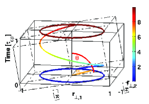
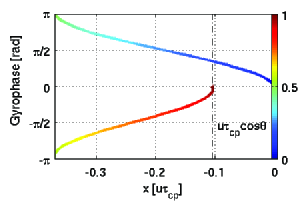
It is known from Figs.3 and 4 of Ref.[21] that the dominant collectively excited modes propagate in the negative -direction with . Modes with slightly lower amplitude are excited propagating in the opposite direction with similar phase speed. These phase velocities are located near the maxima of transient speeds, in either direction along the simulation domain, of the energetic ions that drive the instability. These occur (see Figs. 1 and 2) at gyrophase and ; see also panel (a) of Fig.2 of Ref.[22].
3 Simulation results
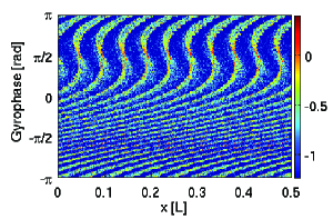
We now turn to the resonant wave-particle interaction as manifested by the distribution of energetic protons along the physical co-ordinate and with respect to gyrophase angle . Figure 3 plots (left) the whereabouts of particles in phase space at , towards the end of the linear phase of the LHDI in this scenario, and (right) the corresponding distribution of particle energies. Within the spatial limits of the simulation box, there are 21 gyrophase bunched structures which span the whole gyrophase range: 10.5 of these are visible in Fig 3, because data from only half of the simulation domain is shown (Figs 3 to 6 all show data from only half of the spatial domain for reasons of pictorial resolution). The simulation domain length proton Larmor radii. This is sufficiently large that protons undergo gyro-orbits per boundary crossing, which corresponds to approximately one boundary crossing per proton during the entire simulation. Figure 3 demonstrates that the rapidly varying behaviour of the distribution in the negative domain of phase space is a continuation of the slower variation in the positive domain. This new result is not apparent from previous analysis of the LHDI in this regime, for example Fig.5 of Ref.[21] and Fig.4 of Ref.[22].
There are 10.5 gyrophase bunched structures per half-box because the simulation box accommodates 21 wavelengths of the wave that is found to be spontaneously excited. This is demonstrated in Fig. 4, which plots the spatial distribution of electrons at the snapshot in time shown in Fig.3, and also confirms that the predominantly electrostatic excited wave is primarily a charge density oscillation supported by the electrons.
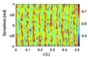
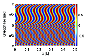
Figure 3 (left) captures wave excitation by the energetic ions as it occurs. The strong spatially dispersive distortion at corresponds (see Fig.1) to the maximum negative particle velocity (see also Fig.2(a) of Ref.[22]), which is located between the points in gyrophase where the resonant drive of the dominant backward-propagating waves takes place. The speed of the dominant wave is slightly smaller than the maximum speed of the protons. Consequently there are two positions of resonance in gyrophase, either side of the maximum negative velocity. These resonant perturbations apparently condition the long-wavelength (in gyrophase ) structure across the positive- domain of phase space. At , which corresponds to the maximum positive particle velocity, the consequences of resonance are apparent in the moiré pattern (which is more easily visible in Fig.3 (right)). While both these velocity resonances give rise to significant (but differing by an order of magnitude) concentrations of electromagnetic field energy in ()-space, as shown in Fig.3 of Ref.[21], it follows from Fig.3 that the phase space consequences are different in the two cases. The number of moiré s-shaped features in the lower half plane of Fig.3 exceeds that in the upper half plane. This reflects the difference in for the waves excited at the two resonances, see again Fig. 3 of Ref.[21].
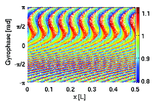
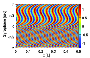
Figure 3 (right) assists interpretation of the physics in terms of the simplified analytical model for the dynamics of the particle-wave interaction that was introduced in Eqs.(12) to (16) of Ref.[22]. The essence of this model is that the impact of wave-particle interaction, for a proton with initial gyrophase at and at arbitrary , scales with the magnitude of the electric field which that proton experienced when it was most closely in phase resonance with the wave. This resonance will have occurred at time such that , where and are the angular frequency and wavenumber of the dominant excited mode in the simulation, obtained from the analysis of the Fourier transform of the electromagnetic field in Figs.3 of Refs.[21]. Given an energetic proton moving on an unperturbed orbit drawn from the drifting beam distribution specified previously, expressions for and position follow from Eqs.(14) and (15) of Ref.[22]. The key point is that the field amplitude, experienced at the point of resonance , which is given by Eq.(16) of Ref.[22], is considered a property of the proton at all subsequent . Figure 5 (left) plots for a population of energetic protons that is initially uniformly distributed in space and gyrophase angle at an arbitrary time . Figure 5 (right) is derived from the analytical model using the three waves identified from the Fourier transform of the excited electromagnetic field that is generated by the PIC simulation during its linear phase. To construct it we repeat the operation used for Fig. 5 (left) while adding: a second wave whose are those identified as the harmonic of the dominant backward travelling wave in the Fourier transform , and whose amplitude is smaller by a factor ten; and a third wave whose are those identified for the forward travelling excited wave in the Fourier transform , and whose amplitude is smaller by a factor four.
Figure 5 (right) appears to capture the key features of Fig.3 (right). This analytical model is based on unperturbed proton gyro-orbits, and Fig. 5 shows that these suffice to recreate gyrobunching effects seen in the PIC simulations provided perturbations are small in the sense that: the resonant gyrophase angles are sharply defined; and the spatial deviation of the resonant particles from their unperturbed orbits is small compared to the wavelength.
This analytical model is based on unperturbed proton gyro-orbits and is able to recreate gyrobunching effects seen in the PIC simulation. This is the case because perturbations are small, in the sense that the resonant gyrophase angles are sharply defined and the spatial deviation (as distinct from gyrophase deviation) of the resonant particles from their unperturbed orbits is also small.
4 Conclusions
Analysis of the distribution in physical space and gyrophase angle of a drifting ring-beam population of energetic ions, as they drive the linear phase of the lower hybrid drift instability in a 1D3V PIC simulation, yields insights into the underlying plasma physics. The spatial coherence and spatial variation of the gyrophase bunched structures are shown to reflect a combination of cyclotron-type and beam-type dynamical and resonant effects, conditioned by the interplay of ion and electron dynamics. These new results shed fresh light on the hybrid character of the lower hybrid drift instability.
Resonant energy transfer occurs at the narrowly defined gyrophases at which the instantaneous speed of an energetic proton, from the drifting ring-beam population, on its cyclotron orbit precisely matches the phase velocity of the lower hybrid wave along the simulation domain. As in any resonant wave-particle instability, coupling to a wave that can propagate is necessary. In the present case, it is electron space-charge oscillation (Fig. 4) that determines the wavelength of the propagating lower hybrid wave, and thereby governs the spatial distribution of gyrobunching of the energetic protons (Figs. 3 and 5) that drive the instability. The gyrophase structure of phase space bunching at any given position is governed by the proton trajectories on their cyclotron orbits, which are oblique to the direction of propagation of waves along the simulation domain, in conjunction with restrictions on the spatial separation of gyrobunches due to collective electron oscillation.
Many of the key features of the wave-particle interaction that we observe in the simulations can be understood retrospectively in terms of a simplified analytical model. However this model is wholly reliant on PIC code outputs for its specification, including the number of waves, their relative amplitudes, and their frequencies and wavenumbers.
This analysis was carried out for plasma parameters that approximate, where computationally affordable, edge plasma conditions in a large tokamak. While the physics is generic, we note that this scenario is motivated by observations of ion cyclotron emission from JET[15] and TFTR [19], and may be relevant to alpha channelling[21, 22].
References
References
- [1] R. C. Davidson, N. T. Gladd, C. S. Wu, and J. D. Huba. Effects of finite plasma beta on the lower-hybrid-drift instability. Physics of Fluids, 20(2):301–310, 1977.
- [2] J. B. Hsia, S. M. Chiu, M. F. Hsia, R. L. Chou, and C. S. Wu. Generalized lower-hybrid-drift instability. Physics of Fluids, 22(9):1737–1746, 1979.
- [3] O. J. G. Silveira, L. F. Ziebell, R. Gaelzer, and Peter H. Yoon. Unified formulation for inhomogeneity-driven instabilities in the lower-hybrid range. Phys. Rev. E, 65(3):036407, Feb 2002.
- [4] William Daughton, Giovanni Lapenta, and Paolo Ricci. Nonlinear evolution of the lower-hybrid drift instability in a current sheet. Phys. Rev. Lett., 93(10):105004, Sep 2004.
- [5] Zoltan Dobe, Kevin B. Quest, Vitali D. Shapiro, Karoly Szego, and Joseph D. Huba. Interaction of the solar wind with unmagnetized planets. Phys. Rev. Lett., 83(2):260–263, Jul 1999.
- [6] Peter H. Yoon, Anthony T. Y. Lui, and Chia-Lie Chang. Lower-hybrid-drift instability operative in the geomagnetic tail. Physics of Plasmas, 1(9):3033–3043, 1994.
- [7] J. F. Drake, P. N. Guzdar, A. B. Hassam, and J. D. Huba. Nonlinear mode coupling theory of the lower-hybrid-drift instability. Physics of Fluids, 27(5):1148–1159, May 1983.
- [8] N T Gladd. The lower hybrid drift instability and the modified two stream instability in high density theta pinch environments. Plasma Physics, 18(1):27–40, 1976.
- [9] T. A. Carter, H. Ji, F. Trintchouk, M. Yamada, and R. M. Kulsrud. Measurement of lower-hybrid drift turbulence in a reconnecting current sheet. Phys. Rev. Lett., 88(1):015001, Dec 2001.
- [10] P. E. Devine, S. C. Chapman, and J. W. Eastwood. One- and two-dimensional simulations of whistler mode waves in an anisotropic plasma. Journal of Geophysical Research-Space Physics, 100:17189–17204, September 1995.
- [11] M. Oppenheim, D. L. Newman, and M. V. Goldman. Evolution of electron phase-space holes in a 2D magnetized plasma. Phys. Rev. Lett., 83(12):2344–2347, Sep 1999.
- [12] M. E. Dieckmann, S. C. Chapman, A. Ynnerman, and G. Rowlands. The energy injection into waves with a zero group velocity. Physics of Plasmas, 6:2681–2692, July 1999.
- [13] P. C. Birch and S. C. Chapman. Detailed structure and dynamics in particle-in-cell simulations of the lunar wake. Physics of Plasmas, 8(10):4551–4559, 2001.
- [14] P. C. Birch and S. C. Chapman. Particle-in-cell simulations of the lunar wake with high phase space resolution. Geophys. Res. Lett., 28(2):219, 2001.
- [15] G. A. Cottrell and R. O. Dendy. Superthermal radiation from fusion products in JET. Phys. Rev. Lett., 60(1):33–36, Jan 1988.
- [16] G. A. Cottrell, V. P. Bhatnagar, O. Da Costa, R. O. Dendy, J. Jacquinot, K. G. McClements, D. C. McCune, M. F. F. Nave, P. Smeulders, and D. F. H. Start. Ion cyclotron emission measurements during JET deuterium-tritium experiments. Nuclear Fusion, 33(9):1365–1387, 1993.
- [17] K. G. McClements, C. Hunt, R. O. Dendy, and G. A. Cottrell. Ion cyclotron emission from JET D-T plasmas. Phys. Rev. Lett., 82(10):2099–2102, Mar 1999.
- [18] R. O. Dendy, K. G. McClements, C. N. Lashmore-Davies, G. A. Cottrell, R. Majeski, and S. Cauffman. Ion cyclotron emission due to collective instability of fusion products and beam ions in TFTR and JET. Nuclear Fusion, 35:1733–1742, Dec 1995.
- [19] S. Cauffman, R. Majeski, K. G. McClements, and R. O. Dendy. Alfvénic behaviour of alpha particle driven ion cyclotron emission in TFTR. Nuclear Fusion, 35(12):1597–602, 1995.
- [20] K. G. McClements, R. O. Dendy, C. N. Lashmore-Davies, G. A. Cottrell, S. Cauffman, and R. Majeski. Interpretation of ion cyclotron emission from sub-Alfvénic fusion products in the Tokamak Fusion Test Reactor. Physics of Plasmas, 3(2):543–553, 1996.
- [21] J. W. S. Cook, S. C. Chapman, and R. O. Dendy. Electron current drive by fusion-product-excited lower hybrid drift instability. Phys. Rev. Lett., 105(25):255003, Dec 2010.
- [22] J. W. S. Cook, S. C. Chapman, and R. O. Dendy. Submitted to Plasma Physics and Controlled Fusion, arXiv:1010.2099v1 [physics.plasm-ph].
- [23] Nathaniel J. Fisch and Jean-Marcel Rax. Interaction of energetic alpha particles with intense lower hybrid waves. Phys. Rev. Lett., 69(4):612–615, Jul 1992.
- [24] N. J. Fisch. Transformer recharging with alpha channeling in tokamaks. Journal of Plasma Physics, 76:627–634, 2010.
- [25] N. J. Fisch. Confining a tokamak plasma with rf-driven currents. Phys. Rev. Lett., 41(13):873–876, Sep 1978.
- [26] C. F. F. Karney, N. J. Fisch, and F. C. Jobes. Comparison of the theory and the practice of lower-hybrid current drive. Phys. Rev. A, 32(4):2554–2556, Oct 1985.
- [27] R. O. Dendy, B. M. Harvey, M. O’Brien, and R. Bingham. Fokker-Planck modeling of auroral wave-particle interactions. J. Geophys. Res., 100:21973–21978, November 1995.