Research Institute for Nuclear Problems, Minsk, Belarus \PACSes\PACSit41.60.-m,41.75.-i \PACSit42.25.-p
Generation of Medical X-ray and Terahertz Beams of Radiation Using Table-Top Accelerators
Abstract
Theoretical and experimental studies of PXR and diffracted radiation of an oscillator in crystals combined with the development of VFEL generators with photonic crystals give a promising basis for creation of X-ray and THz sources using the same table-top accelerator. Multi-modal medical facility can be developed on the basis of one dedicated table-top electron accelerator of some tens of MeV energy. Such a system could find a lot of applications in medical practice and biomedical investigations.
In the Executive Summary of the first Workshop “Physics for Health in Europe” held in February 2010 at CERN is stressed that dose reduction during diagnostic radiology and CT examinations is a hot research topic worldwide [1]. Development of new intensive (quasi)-monochromatic tunable x-ray and terahertz sources is an important part of such research.
Medical quasi-monochromatic X-ray beams must have an essential integral flux to provide high-quality high-contrast imaging. Also, realistic sources of these beams must have laboratory sizes and affordable price to be used in clinics and hospitals. The main problem in development of monochromatic X-ray sources is the gap between the achievable photon generation efficiency (photon per electron) and the existing electron beam current in the table-top accelerators. Another problem is strong scattering of an electron moving through a single crystal target. We showed [2] that an X-ray source with the required properties can be developed using parametric X-rays (PXR) from charged particles in a crystal [3] and table-top accelerators like compact storage ring or pulsed race-track microtron [4, 5, 6, 7, 8].
Accelerators of a kind can also be used for the development of the intense terahertz source based on the mechanism of the volume free electron laser [9]. Today, THz technology is finding a variety of applications: information and communications technology; biology and medical sciences; non-destructive evaluation and homeland security; quality control of food and agricultural products; global environmental monitoring, space research and ultra-fast computing [10]. High-power tunable T-ray sources are very important devices to bring THz research from promising prospects to a wide use in science and technology.
T-rays are also very promising for biomedical applications: low energy of photons prevents them from ionizing biological media, but this energy corresponds to vibrational levels of important bio molecules including DNA and RNA. This allows direct action for stimuling viruses, cells, their components and provides control of bio-chemical reactions. Thus, T-rays may be applied in therapy, surgery, imaging, and tomography. Terahertz radiation is extremely important for bio-medical applications and its wider use depends on the progress in development of THz sources [11].
In present paper we discuss prospects of application of diffracted radiation of an oscillator (DRO) (sometimes called diffracted channeling radiation - DCR) for X-ray source creation. DRO is the coherent process of diffracted X-ray photon emission by the relativistic oscillator (electron channeling in a crystal). DRO formation was first considered in [12], detailed review and references may be found in [13, 14]. Evaluations show that DRO generation efficiency per one electron is some times higher than that of PXR and diffracted Bremsstrahlung.
The same radiation mechanisms can work in the terahertz range if a single crystal target is changed for the photonic crystal of appropriate properties [15, 16, 17, 18]. Thus, multi-modal medical facility can be developed on the basis of one dedicated table-top electron accelerator of several tens of MeV energy.
1 Generation of Medical X-ray
The principal question arises: what do we need for high-quality in vivo medical imaging?
Current understanding shows, that we need approximately photons/s with tunable X-ray energy in 10-70 keV spectral range [1, 2]. Monochromaticity should be of and lower for a patient’s dose reduction. Radiation background should be low.
Besides the above mentioned PXR [2], electrons (positrons) moving in a crystal radiate X-rays due to two more mechanisms:
b). diffracted radiation of a relativistic oscillator (DRO), which is also often called diffraction channelling radiation (DCR) [12] (detailed review and references can be found in [13, 14]).
According to the analysis [13], the DCR to PXR ratio for electrons of 34 MeV energy channelled in a target between (100) planes and radiation diffracted by (220) planes is estimated as R5 ().
For qualitative analysis, the DCR intensity can be evaluated as a product of intensity of channelled radiation and reflection coefficient for Bragg diffraction in the defined range of angles and frequencies.
At first glance the idea for a new type of X-ray source could be to combine two crystals: X-rays emitted from the particles channelled in the first crystal obtain the required spectral and angular distributions due to diffraction in the second one.
Nevertheless, the possibility of anomalous transmission of X-rays diffracted in a crystal (Bormann effect [21]) should be remembered. In this case the coefficient of X-rays absorption becomes lower and the intensity of DCR (DRO) can appear higher than that of conventional channelling radiation. The radiation intensity is proportional to the path length of the particle inside the crystal indeed while it becomes comparable with the absorption length (if the dechannelling length exceeds the absorption path). The absorption path in the presence of diffraction can be much longer than that in the absence of diffraction. The above is especially important in the X-ray frequency range, for which absorption in the absence of diffraction is high.
That is why the X-ray source based on DCR mechanism could be more powerful.
2 Terahertz radiation (T-rays)
The above described mechanisms of photon radiation by a relativistic particle passing through a crystal (PXR,SPXR,DRO) have general nature and holds for a particle moving either through an artificial (photonic) crystal or along its surface. Photonic crystals (diffraction gratings) can be made with various spatial periods and thereby provide radiation in different wavelength ranges from microwave to optical and even soft X-rays. Note that radiation from a relativistic particle moving in either natural or artificial crystal is spontaneous radiation. Obviously, the induced radiation could also exist.
Generation of radiation in millimeter and far-infrared range with nonrelativistic and low-relativistic electron beams is a complicated task. Gyrotrons and cyclotron resonance facilities are used as sources in millimeter and sub-millimeter range, but for their operation a magnetic field of several tens of kiloGauss is necessary. Slow-wave devices (TWT, BWT, orotrons) in this range require application of dense and thin (mm) electron beams because only electrons passing near the slowing structure at a distance can effectively interact with electromagnetic waves ( is the Lorentz factor, is the wavelength, , is the particle velocity). For 1 THz frequency cm, therefore, for an electron with energy of 50 MeV (), the above discussed distance cm. It is difficult to guide thin beams near a slowing structure with desired accuracy. Conventional waveguide systems are essentially restricted by the requirement for transverse dimensions of a resonator, which should not significantly exceed the radiation wavelength. Otherwise, the generation efficiency decreases abruptly due to the excitation of plenty of modes. Most of the above problems can be overcome in Volume Free Electron Lasers (VFEL) [13, 14, 15, 18, 19].
In volume FELs, the greater part of the electron beam interacts with an electromagnetic wave due to volume distributed interaction. Transverse dimensions of a VFEL resonator could significantly exceed radiation wavelength . Multi-wave Bragg dynamical diffraction provides mode discrimination in VFELs.
Moreover, in VFEL a lasing regime discovered in [22] can be realized. It provides drastic increase in the efficiency of the electron beam interaction with the emitted electromagnetic wave due to the interception of roots of the dispersion equation describing radiative instability of the electron beam in a 3-dimensional spatially periodic medium.
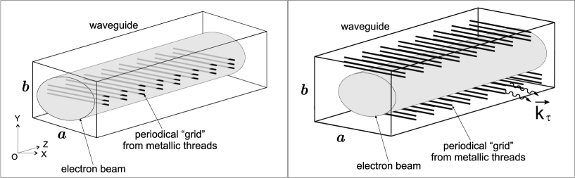
Let us consider an electron beam with velocity passing through a periodic structure composed of either dielectric or metal threads (see Figure 1).
Fields, appearing while an electron beam passes through a volume spatially periodic medium, are described by the set of equations given in [13, 14, 25]. Instability of the electron beam is described by the dispersion equation [13, 14, 16, 23, 24, 25]:
| (1) |
is the wave vector of the diffracted photon, are the reciprocal lattice vectors, are the translation periods, is the part of dielectric susceptibility caused by the presence of the electron beam. Two different types of instability exist, depending on the radiation frequency. Amplification takes place when the electron beam is in synchronism with the electromagnetic component , which has a positive projection . If the projection is negative and the generation threshold is reached, then generation evolves. In the first case, radiation propagates along the transmitted wave which has a positive projection of group velocity , and beam disturbance moves along it. In the second case, the group velocity has a negative projection , and radiation propagates along the back-wave and the electromagnetic wave comes from the range of the greatest beam disturbance to the place, where electrons come into the interaction area. For a one-dimensional structure, such a mechanism is realized in a backward-wave tube. In amplification case, equation (1) gives for the increment of instability: , where
if the condition is fulfilled. Here , if the electron beam propagates in a strong guiding magnetic field, otherwise, , is the beam velocity. In case a dissipative instability evolves. Its increment is
If inequalities and are fulfilled, the spatial increment of instability can be expressed as
but the parameters providing such dependence correspond to the conversion from the amplification to the generation regime (for the Compton instability this situation takes place at ). The frequency of amplified radiation is defined as:
| (2) |
The instability in the generation regime is described by the temporal increment and cannot be described by the spatial increment. The increment of absolute instability can be found by solving the equation with respect to the imaginary part of [14].
The use of Bragg multi-wave distributed feedback increases the generation efficiency and provides discrimination of generated modes. If the conditions of synchronism and Bragg conditions are not fulfilled simultaneously, diffraction structures with different periods can be applied [14, 26]. One of them provides synchronism of the electromagnetic wave with the electron beam . The second diffraction structure evolves distributed Bragg coupling , () are the reciprocal lattice vectors of the second structure.
Under dynamical diffraction conditions either the generation start current or the length of the generation zone at certain values of the current can be reduced [13, 14, 19, 22].
Each Bragg condition holds one of free parameters. For example, for certain geometry and electron beam velocity, two conditions for three-wave diffraction entirely determine transverse components of wave vectors and , and therefore the generation frequency. Hence, volume diffraction system provides mode discrimination due to multi-wave diffraction.
The above results affirm that a volume diffraction structure provides both amplification and generation regimes even in the absence of dynamical diffraction. In the latter case, generation evolves with backward wave, similarly to the backward-wave oscillator. The frequency in such structures is changed smoothly either by a smooth variation of the radiation angle (variation of and ), or by the rotation of the diffraction grating or the electron beam. For certain geometry and reciprocal lattice vector, amplification corresponds to higher frequencies than generation. Rotation of either the diffraction grating or the electron beam also changes the value of the boundary frequency, which separates generation and amplification ranges. The use of multi-wave distributed feedback owing to Bragg diffraction allows one either to increase the generation efficiency or to reduce the length of the interaction area.
In the case of our interest, a T-ray source generating either backward or following waves with a wavelength of 0.3 mm should have the period of the diffraction grating providing Bragg coupling 0.16 mm that is a challenge.
It is interesting that according to [15, 16, 18], for a photonic crystal made from metallic threads, the coefficients , defining the threshold current and the growth of the beam instability, are practically independent of up to the terahertz range of frequencies because the diameter of the thread can easily be made smaller than the wavelength. As a result, an electromagnetic wave is sufficiently strongly coupled with the diffraction grating (the coefficient of diffraction reflection is sufficiently high) even for ( is the photonic crystal (diffraction grating) period) to provide efficient radiation in Backward Wave Oscillator (BWO) and Travelling Wave Tube (TWT) regimes. That is why photonic crystals with the period of several millimeters can be used for lasing in terahertz range at high harmonics (for example, photonic crystal with a 3 mm period provides the frequency of the tenth harmonic of about 1 terahertz (=300 micron) [16].
Note here that a photonic crystal built from metallic threads has the refractive index for a wave with the electric polarizability parallel to the threads, i.e., in this case the Cherenkov instability of the beam does not exist [15] and radiation appears only due to diffraction of waves. But if the electric vector of the wave is orthogonal to the metallic threads, the refractive index is , so for such a wave, the Cherenkov instability exists [27] even in the absence of diffraction.
The ”grid” structure formed by periodically strained dielectric threads was experimentally studied in [28], where it was shown that ”grid” photonic crystals have sufficiently high factors (). Lasing from VFELs with the ”grid” resonator formed by periodically strained metal threads was observed in [9].
Use of the volume distributed feedback in a photonic crystal makes available:
1. frequency tuning at fixed energy of the electron beam in a significantly wider range than conventional systems can provide;
2. significant reduction of the threshold current of the electron beam due to more effective interaction of the electron beam with the electromagnetic wave, allowing, as a result, miniaturization of generators;
3. simultaneous generation at several frequencies;
4. effective modes selection in oversize systems, in which the radiation wavelength is significantly smaller than the resonator dimensions.
References
- [1] http://cdsweb.cern.ch/record/1269323/files/PHEE-10_EN.pdf
- [2] \BYBaryshevsky V., Feranchuk I., Gambaccini M., Lobko A.\atqueTaibi A. Abstracts of Intl. Workshop “Physics for Health in Europe” (CERN Geneva Switzerland, 2-4 February 2010), Book of Abstracts, p. 48;
- [3] \BYBaryshevsky V., Feranchuk I. \atqueUlyanenkov A. \TITLEParametric X-ray Radiation in Crystals: Theory, Experiment and Applications, (Springer) 2006.
- [4] \BYTsipenyuk Y.M., \TITLEMicrotron: Development and Applications. (CRC Press) 2001.
- [5] http://vserv.sinp.msu.ru/ebl/index.php?subcat=0.
- [6] \BYMinkov D., Moritab M., Nihirac H., Yamada H. \INNucl. Instr. Meth.590A2008110.
- [7] \BYLidbjrk P., strm J. \INProc. IEEE 1993 Particle Accelerator. Conf.93CH3279-71993 2068.
- [8] \BYHuang Z., Ruth R.D. \INPhys. Rev. Lett.801998976.
- [9] \BYBaryshevsky V., Belous N., Gurinovich A., Gurnevich E., Evdokimov V., Molchanov P. \INProceedings of FEL2009, Liverpool, UKMOPC492009134, http://www.JACow.org
- [10] \BYMasayoshi Tonouchi \INNature Photonics1200797.
- [11] \BYKazarinov K.D. \INElectronnaya Technika, ser. 14(503)200948 (in Russian)
- [12] \BYBaryshevsky V.G., Dubovskaya I.Ya. \INDoklady Akad. Nauk SSSR23119761336 (in Russian);
- [13] \BYBaryshevsky V.G., Dubovskaya I.Ya. \TITLEDiffraction phenomena in spontaneous and stimulated radiation by relativistic particles in crystals, Lawrence Berkeley Laboratory, LBL-31695 (1991).
- [14] \BYBaryshevsky V.G. arXiv:physics/1101.0783v1.
- [15] \BYBaryshevsky V.G., Gurinovich A.A. \INNucl. Instr. Meth.252B200692; arXiv:physics/0409107.
- [16] \BYBaryshevsky V.G., Gurinovich A.A. arXiv:physics.acc-ph/1011.2983
- [17] \BYBaryshevsky V.G., Batrakov K.G., Stolyarsky V.I. \INNucl. Instr. Meth.507A200393
- [18] \BYBaryshevsky V.G., Gurinovich A.A. \INProceedings of FEL’06TUPPH0132006335; http://www.JACoW.org; arXiv:physics/0608068v1[physics.acc-ph].
- [19] \BYBaryshevsky V.G. \INDoklady Akademii Nauk SSSR29919886; \INNIM445A2000281.
- [20] http://www.ppl-xray.com; http://vserv.sinp.msu.ru/ebl/index.php?subcat=0;
- [21] \BYJames R.W. \TITLEThe Optical Principles of the Diffraction of X-rays (Ox Bow Press) 1982.
- [22] \BYBaryshevsky V., Feranchuk I. \INPhys. Lett.102A1984141.
- [23] \BYBaryshevsky V., Batrakov K., Dubovskaya I. \INJ.Phys.D2419911250.
- [24] \BYBaryshevsky V.G., Batrakov K.G., Dubovskaya I.Ya. \INNucl. Instr. Meth.375A1996292.
- [25] \BYBaryshevsky V.G., Batrakov K.G., Dubovskaya I.Ya. \INNucl. Instr. Methods358A1995493.
- [26] \BYBaryshevsky V.G., Batrakov K.G., Stolyarsky V.I. Proceedings of 21-st FEL Conference (1999) 37.
- [27] \BYBaryshevsky V.G., Gurnevich E.A. Proc. Of 2010 International Kharkov Symposium on Physics and Engineering of Microwaves, Milimeter and Submilimeter Waves (MSMW’10), 21-26 June 2010, DOI:10.1109/MSMW.2010.5546019, p. 1-3.
- [28] \BYBaryshevsky V.G., Batrakov K.G., Dubovskaya I.Ya., Karpovich V.A., Rodionova V.M. \INNucl. Instr. Methods393A199771.