Specular holography
Abstract
By tooling an spot-illuminated surface to control the flow of specular glints under motion, one can produce holographic view-dependent imagery. This paper presents the differential equation that governs the shape of the specular surfaces, and illustrates how solutions can be constructed for different kinds of motion, lighting, host surface geometries, and fabrication constraints, leading to some novel forms of holography.
1 Holography via specular glints
Holography, broadly understood, is any means of making a light field that contains a range of views of a virtual 3D scene. Using only geometric optics, it is possible to construct a sparse holographic light field by tooling a 2D surface to control the bundle of rays it directionally reflect or refracts. The author has been exhibiting such “specular holograms” in public art venues for a number of years. This paper introduces the differential geometry that determines the geometry of the optical surfaces, and develops solutions for several viewing geometries.
The idea of specular holography predates wavefront holography by many years. The centuries-old arts of metal intaglio and engine turning exploit the fact that sharp glints on smooth convex specular surfaces appear—via stereopsis—to float below the surface. Beginning in the 1930’s, several authors have analyzed this effect [1, 2, 3, 4] and proposed to use it for view-dependent imagery [5] and holography [6, 7, 8, 9, 10, 11] using surface scratches or parabolic reflectors. All give reasonable approximations for small ranges of viewpoints; this paper gives the exact geometry for all viewpoints.
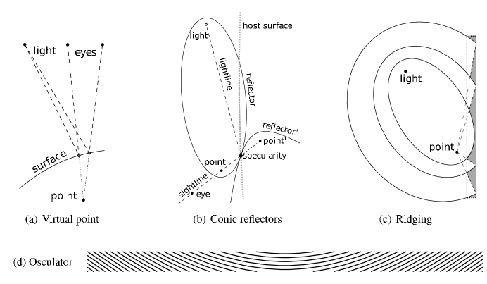
Fig. 1(a) diagrams the optical principle: Given a point light source and a virtual 3D point in the holographic scene, one shapes a smooth optical surface that reflects or refracts a specular glint to the eye along every unoccluded sightline through the point. The surface appears dark to other sightines. Lacking any other depth cues, the brain parsimoniously but incorrectly concludes that both eyes see a single specularity located at the virtual point. Changes in viewpoint reinforce the 3D percept via motion parallax.
A specular hologram combines a large number of such optical surfaces, all designed to conform to a 2D host surface so that they can be easily formed by conventional fabrication techniques such as milling, grinding, stamping, ablation, etc. The host surface has limited surface area, so the 3D virtual scene is represented by a sparse sampling of its points, usually a stippling of its surfaces. As an artistic matter, there are many ways to algorithmically produce visually informative and pleasing stipplings. Similarly, the optical surfaces have a simple differential geometry, developed below, that admits a variety of distinct solutions.
2 Geometry of a single-point optical surface
Consider making a specular hologram of a single point . Let be a point illumination source, and let be the location of the eye. Typically the viewpoint is parameterized by azimuth and elevation ; and can vary parametrically as well. Throughout this paper, a boldfaced variable will refer interchangeably to a three-vector and the function giving its locus. The holographic effect is achieved by producing a specular glint on each sightline through virtual point at a real point where the axis of reflection or refraction is parallel to the optical surface normal . The ideal optical surface is a continuous locus of points swept by as vary. Generally, there is an infinite foliation of such surfaces, each a different distance from on the sightline. To fabricate the hologram, a host surface with local normal is tooled to conform piecewise to this foliation, changing its local normal to .
As in computational mirror design [12], one needs to reconstruct a surface from a field of arbitrarily scaled normals. Here it is more convenient work with tangent spaces than with normals. Let be any nondeficient basis of the optical surface’s local tangent plane at . For example, could be the Jacobian of with respect to . Then the constraints that determine the optical surface are
| (1) | |||||
| (2) | |||||
| (3) |
where are the refractive indices of materials a light ray crosses before and after encountering the optical surface; and are the Euclidean inner product and vector norm; and is any orthogonal basis of the nullspace of , i.e., . For reflection holography, . Differential Eq. (1) (normality) states that the optical surface is perpendicular to the axis of reflection or refraction. Eq. (2) (colinearity) ensures that the specularity is on the sightline to Eq. (3) (conformance) specifies that the optical surface lie within a thin shell of thickness that conforms to the host surface . The colinearity constraint can be algebraically eliminated by sliding the eye forward along the sightline until it coincides with or .
It is easily shown (by substitution) that Eq. (1) is satisfied by a foliation of revolute bicircular quartics with foci at and . The quartics are revolved around the major axis connecting and .
The most common case of interest is a reflection hologram with static point light source and virtual point . In this case the quartics simplify to conics. Specifically, if is in front of the reflecting surface, the solution is the interior surface of any prolate ellipsoidal reflector with eccentricity . If point is behind the reflecting surface, the solution is the exterior surface of any hyperboloid of eccentricity . Fig. 1(b) illustrates how these two solutions111There are also two degenerate solutions: The exterior of an infinitesimal parabolic needle for at the surface (), the interior of a sphere for at light source (). are related.
The remaining constraint (Eq. (3)) can be satisfied by constructing a ridged surface from the foliation that conforms to the host surface. Fig. 1(c) illustrates the construction. Each ridge is the intersection of a thin shell at the host surface, a cone emanating from some point in front of the host surface, and a revolute conic (or its complement) taken from the foliation. This construction works for arbitrary host surfaces, however, as with all Fresnel-like surfaces, the resulting optical surface may self-occlude some rays.
In a hologram, each stipple generates a ridged optical surface, which is cropped to a small region on the host surface to limit azimuthal and elevation visibility intervals. Cropping can be used to suggest occlusion, illumination, and shading effects in the virtual scene; and for viewpoint-keyed animation.
An early instance of an approximate specular holographic surface is the 1961 VITA solar cooking stove. In this case, the sun is at (effectively, infinity), the pot is at , and the host surface is a plane perpendicular to the ellipsoid’s medial axis. A conic with one focus at infinity is a paraboloid, hence the stove uses a Fresnel paraboloidal reflector. Stoves with finer ridgings produce strong depth illusions. A similar construction is used in [11], who report producing a depth illusion for an azimuthal view range of up to , albeit with distortions.
For refracting holograms, the exact optical surfaces are generally not conics. For single-interface optical paths, Eq. (1) is solved by a foliation of revolute Cartesian ovals. Proper modeling of two-surface optical paths typically leads to numerical integration, with some notable exceptions. Given a planar back surface, a focusing front surface can be derived from Fermat’s principle, yielding an parametric sag function. In typical settings the point light source is far enough behind the back surface that the ray bundle incident on the front surface is approximately radially divergent, in which case the front surface can be very tightly approximated by a revolute Cartesian oval with one focus shifted from to the center of divergence. This approximation becomes exact for divergent light on a spherically-backed surface and for collimated light on a flat-backed surface, in which case the classical geometry of plano-aspheric lenses (e.g, [13]) provides a foliation of hyperbolic or elliptic front surfaces, depending on the ratio of refractive indices and whether the virtual point is in front of or behind the refracting surface. Of course, if both front and back surfaces are machined, the problem reduces to classic aspheric lens design.
3 Horizontal parallax via osculating surfaces
Ridged surfaces are imperfect optics: Some rays founder on the non-imaging backface of each ridge, causing stray specularities and dead spots. In practice, ridged surfaces proved to be tedious and difficult to machine cleanly at small scales. This motivated a switch to smoother osculating surfaces that are easy to fabricate rapidly and finely. An osculating surface “kisses” the foliation by matching its surface normals on a bounded submanifold of contact points. I.e., there is some region where the osculating surface produces the same specularities. A trivial example arises when machining an optical surface with a ball-end milling bit: Each pass of the bit sweeps a volume whose surface osculates the desired surface. Swept volumes can be machined much faster and smaller than ridged surfaces, enabling far more detailed stippings in less time. For example, a recently exhibited hologram has roughly stipples; current fabrication methods are approaching stipples/second for -view holograms.
A swept volume that provides horizontal parallax to all viewpoints can be determined analytically for many viewing geometries: Eq. (1) determines a tangent space for every point in . Integrating the component of these tangents that conforms to the host surface yields a foliation of toolpaths that sweep the surface. Integrating the orthogonal component yields the profile of the cutting bit.
To illustrate, consider a reflective optical surface embedded in a locally flat host surface, lit by the sun at azimuth , elevation (at high noon, ), and producing a light field with horizontal parallax. Here it is useful to imagine an infinitely thin and long mirrored cylinder laid flush on the host surface and angled such that an eye looking along a ray from azimuth , elevation sees a specular glint. Using a local coordinate frame centered on the specularity, the cylinder axis is a vector through the origin in the plane, the eye is at and the sun is at . The local host surface normal is and the optical surface normal at the glint is
As per Eq. (1), the local tangent space of the optical surface at glint must be orthogonal to ; i.e., . Without loss of generality, choose optical surface tangent to lie in the local tangent space of the host surface:
| (4) |
Writing yields the slope of the cylinder axis: .
Integrating this slope w.r.t. view angle yields the toolpath that satisfies Eq. (1) as the viewpoint revolves around a virtual point . To this end, one needs the fact that the sightline from to passes through a flat host surface at horizontal location . Integrating then reveals that the toolpath is a hyperbola:
| (5) | |||||
| (6) |
The horizontal locations of specularities on this toolpath are parallax-consistent, but because the specularities travel up and down the “arms” of the hyperbola, they are not on the sightline and therefore Eq. (2) is not satisfied. This can be solved by noting that the integration constant specifies a foliation of identical hyperbolas, all differing by vertical offsets. We take the intersection of this foliation with a thin rectangular bar, then select a subset of discrete hyperbolic arcs that can be machined without destructive overlap. That produces a striping (Fig. 1(d)) similar to the fringe pattern of a single-point hogel in a Benton white-light hologram.
The toolpath sweeps through the conforming tangents of the optical surface. The orthogonal tangents
| (7) |
can be integrated to yield a space curve that osculates the cutting bit, from which the bit profile can be deduced. Because any positive integration measure can be used for , it suffices that the bit profile merely has the range of surface-to-tangent angles exhibited by along the toolpath. For example, assuming an overhead light ( and a flat host surface, the angle varies by over a range of azimuthal viewpoints. Consequently the profile of the cutting bit needs to be slightly curved to produce a swept volume with all the required normals. This curvature also serves to make the holographic images visible to eyes at positive and negative elevations, albeit without vertical parallax.
To extend the swept volume construction to a curved host surface with normal function , assume that the eye moves along some path (e.g., a transverse line), producing a specularity space curve where sightlines through the virtual point intersect the host surface. Define on this curve and calculate and w.r.t. and to obtain a foliation of toolpaths . The desired striping is the intersection of this foliation with a thin shell around the specularity space curve. Generally these curves are not conics.
By appropriate parameterization, the toolpath-and-profile construction will also yield stripings for holograms with arbitrarily located point light sources, discontinuous host surfaces, and motions of the virtual points, light source, or host surface.
Note that the unstriped hyperbolic toolpath is well approximated by a circular arc for a roughly range of azimuthal viewpoints—sufficient for stereopsis from a central viewpoint. This explains the appeal of scratch holography[5, 6, 7, 8, 9, 10], and also why its holographic image distorts and collapses outside that range.
The ease of fabrication of long toolpaths motivates another class of solutions—to be presented in a follow-up paper—where Eq. (1) is used to solve for motions of the virtual scene or the host surface such that all specularities on the continuous (unstriped) toolpath provide rigidly rotated views of the scene.
Roughly 100 holograms have been fabricated over the last few years using all three classes of solutions (ridgings, stripings, and continuous toolpaths), including unusual variants such as animated holograms, continuous -view222For example, a hologram in which the view circles a 3D head twice, seeing a different face in each cycle. planar holograms, and holograms on curved surfaces. From early 2009, pieces have been exhibited in public art venues [14, 15], attracting large crowds. As with all holograms, the pieces are difficult to photograph satisfactorily; so readers are invited to see videos at http://www.zintaglio.com .
References
- [1] P. Kirkpatrick, “A binocular illusion,” Americal Journal of Physics 22, 492–495 (1954).
- [2] J. Lott, “Reflections on a gramophone record,” Mathematics Gazette 47 (1963).
- [3] J. Walker, “What do phonograph records have in common with windshield wipers?” Scientific American 261, 106–109 (1989).
- [4] W. T. Plummer and L. R. Gardner, “A mechanically generated hologram?” Applied Optics 31, 6585–6588 (1992).
- [5] H. Weil, “Improvement in advertising and the like signs,” UK Patent No. 37.208/34 (1934).
- [6] E. Garfield, “ISI’s ’World Brain’ by Gabriel Liebermann: The world’s first holographic engraving,” in “Essays of an Information Scientist,” , vol. 5 (ISI Press, 1981), pp. 348–354.
- [7] W. Beaty, “Hand-drawn holograms,” http://amasci.com/amateur/holo1.html (1995).
- [8] W. Beaty, “Drawing holograms by hand,” in “Proc. SPIE-IS&T Electronic Imaging,” , vol. 5005 (2003), pp. 156–167.
- [9] J. Eichler, L. D nkel, and O. Gon alves, “Three-dimensional image construction by curved surface scratches.” Applied Optics 42, 5627–5633 (2003).
- [10] ngel G. Augier and R. B. S nchez, “Scratch holograms drawn by computer using a laser engraver system,” Revista Cubana de F sica 27, 110–117 (2010).
- [11] C. Regg, S. Rusinkiewicz, W. Matusik, and M. Gross, “Computational highlight holography,” To appear, ACM Transactions on Graphics (Proc. SIGGRAPH Asia) (2010).
- [12] R. A. Hicks, “Designing a mirror to realize a given projection,” J. Opt. Soc. Am. A 22, 323–330 (2005)
- [13] G-I. Kweon and C-H. Kim, “Apherical lnes design by using a numerical analysis” J. Korean Phys. Soc. 51(1), 93–103 (2007)
- [14] “Newton Open Studios, Massachusetts” http://www.newtonopenstudios.com (2009).
- [15] “ArtPrize, Grand Rapids, Michigan” http://www.artprize.org (2009-2010).