Recovering Missing Slices of the Discrete Fourier Transform using Ghosts
Abstract
The Discrete Fourier Transform (DFT) underpins the solution to many inverse problems commonly possessing missing or un-measured frequency information. This incomplete coverage of Fourier space always produces systematic artefacts called Ghosts. In this paper, a fast and exact method for de-convolving cyclic artefacts caused by missing slices of the DFT is presented. The slices discussed here originate from the exact partitioning of DFT space, under the projective Discrete Radon Transform, called the Discrete Fourier Slice Theorem. The method has a computational complexity of (where ) and is constructed from a new Finite Ghost theory. This theory is also shown to unify several aspects of work done on Ghosts over the past three decades. The paper concludes with a significant application to fast, exact, non-iterative image reconstruction from sets of discrete slices obtained for a limited range of projection angles.
Index Terms:
Discrete Radon Transform, Mojette Transform, Discrete Tomography, Image Reconstruction, Discrete Fourier Slice Theorem, Ghosts, Number Theoretic Transform, Limited Angle, Finite Ghost TheoryI Introduction
The DFT is an important tool for inverse problems, where the Fourier representation of an object is used as a mechanism to recover that object. For example, in Computed Tomography (CT), the internal structure of an object is recovered or reconstructed from its projected “views” or projections [1]. The Fourier Transform (FT) of the projections can be placed into Fourier space and the inverse FT is used to reconstruct the object. This is especially advantageous given the efficient and low computationally complex algorithm of the DFT known as the Fast Fourier Transform (FFT) [2]. In such cases, the acquired data cannot fully cover Fourier space as the problem is ill-posed [3, 4]. Thus, there are missing Fourier coefficients and it is common practice to interpolate the space from the known Fourier coefficients. The choice of interpolation method is a major factor in determining the quality of the reconstruction [5, 6].
I-A Ghosts
Incomplete Fourier coverage leads to the introduction of reconstruction artefacts known as “Ghosts” or “invisible distributions” [7]. Ghosts are effectively formed from an under-determined set of projections, i.e. from the “missing” or unmeasured projections. Therefore, Ghosts are always present within CT reconstructions and are the main reason for the filtering and interpolation of projection data [3]. The initial work on Ghosts in continuous space was pioneered by Bracewell and Roberts [7], Logan [3], Katz [8] and Louis [9]. Recent work by Candès et al. [10] has also addressed this issue using more modern methods.
In contrast, projection sets in Discrete Tomography (DT), which have practically well defined reconstruction processes [11], are often deliberately or naturally under-determined for various applications. These applications range from image encoding [12], network transmission [13] to tomography [14]. Discrete Ghosts were first proposed by Katz [8] as a way to describe zero-valued discrete projections taken at rational angles , i.e. (or simply the vector ) where . A simple example of these discrete Ghosts is shown in Fig. 1(a).


Katz [8] determined that an image can be reconstructed exactly from a set of rational angle projections if and only if
| (1) |
This is now known as the Katz Criterion. It is a statement that the information contained in the projection set needs to be one-to-one with the image data. Thus, knowing whether the projections of a sub-region in the reconstruction meets the Katz Criterion will allow one to determine if the sub-region is exactly reconstructable.


Chandra et al. [14, 15] showed that Ghosts also exist in the DFT as cyclic artefacts when DT projection data is missing. These cyclic Ghosts will be referred to as “Finite Ghosts” (see Fig. 1(b)). They showed it was possible to recover missing projection data exactly in DT given a sufficient redundant region in the reconstruction. However, the method could only solve for a very small number of missing projections while still being computationally viable. Their method was also based on empirical observations of the Finite Ghosts.
In this paper, we present a fast method of recovering missing slices from DFT space that may be applied efficiently to very large sets of missing projection data. The method allows exact recovery of these missing slices by removing Ghosts formed within the DFT, a process that will be referred to as “De-Ghosting”. The slices are equivalent to the projections of the Discrete Radon Transform (DRT). A schematic of this process is shown in Fig. 2 using the DRT. The method will utilise a new theory of Ghosts in the DFT constructed in Sec. II. A consequence of the theory are the special one dimensional (1D) Ghost operators shown in Fig. 3 from which the De-Ghosting is computed. The end result is a method to reconstruct an object exactly from a limited number of projections (with incomplete DFT coverage) without interpolation (see Sec. III). The incomplete DFT coverage in this case is restricted to the set of discrete slices of the DFT as described in the next section. It is hoped that a deep understanding of such methods will allow more efficient approaches to inverse problems that utilise the DFT.
I-B Discrete Fourier Slice Theorem
The Discrete Radon Transform (DRT) provides an exact partitioning of DFT space in the form of finite or cyclic slices [16, TIP]. An example of the slice partitioning is given in Fig. 4.


The DRT projections have the same geometry as the slices, i.e. they are taken as lines or congruences of the form
| (2) |
for an image where is the slope, is the translate and . The lines in this geometry wrap around the image in both rows and columns.
In this paper, the term “image” is used interchangeably with a two dimensional (2D) “object” and assume that is prime, which defines the simplest form of the DRT111See Hsung et al. [17] or Chandra et al. [18] for a discussion of the dyadic DRT.. In general, one requires a total of projections for an exact reconstruction for an image, where (which includes powers of two). Thus, the projections are taken along the vectors (with ) and , and the slices are placed along the vectors and in DFT space (see examples shown as arrows in Fig. 4).
Chandra et al. [19, 20] showed that these projections (and lines) are equivalent to circulant matrices (or simply circulants) for all translates (see Fig. 5).
Definition 1 (Circulant [21]).
A circulant is an matrix containing a unique row with replicated on each row, but where each row is cyclically shifted by a certain number of elements to the right.


The property of circulants important here is that a circulant is diagonalised by the 2D DFT. Eq. (13) shows an example of this property, where the values are the eigenvalues of the circulant.
| (13) |
Since each slice in the DFT is obtained by diagonalising its corresponding circulant using the DFT (see Eq. (13)), the placing of each slice in DFT space adds its corresponding circulant to image space until the image is recovered. This is known as Circulant Back-Projection (CBP) [20] and an example of CBP is given in Fig. 6. When all projections are diagonalised, the resulting slices fully tile all of DFT space precisely once (see Fig. 4) allowing the exact reconstruction of the object.

This is made possible by the prime-sized space of the DFT/image, since the always.
The DRT was independently developed by Grigoryan [22], Bolker [23], Gertner [24] and Fill [25]. The partitioning allows for the exact (with ) recovery of images from their projections and is known as the Discrete Fourier Slice Theorem (FST) [22, 26, 16]. Do and Vetterli [27, TIP] utilised the Wavelet Transform on the DRT projections for image compression and de-noising. Chandra [20] extended the DRT to the Number Theoretic Transform (NTT) using the circulant theory of the DRT and showed that the discrete FST still applies. This Number-Theoretic Radon Transform (NRT) will prove critical in the De-Ghosting process later on in this work.
The NRT methods will rely on initial work done by Normand et al. [13]. They generalised the Katz Criterion to arbitrary convex regions by arguing that a region is reconstructable if and only if the size of the Ghost becomes too large to fit within the image region. To show this, they studied the spatial extents of discrete Ghosts, which were determined using Mathematical Morphology.
I-C Ghost Morphology
Ghost structures are constructed using dilations of 2-Point Structuring Elements. A discrete 2PSE is the rational vector as shown in part (a) and (b) of Fig. 7.


A dilation by a 2PSE is the addition of the 2PSE to every point in the current structure [28]. Equivalently, the dilation of by is given by the Minkowski Addition of and as
| (14) |
An example of a dilation is shown in Fig. 7. For constructing Ghost structures, each missing projection has a 2PSE given by their rational angle or vector , so that in Eq. (14) is a 2PSE. The dilations are then applied using all 2PSEs of the missing projection angles to construct a Ghost structure.
In the next section, the theory of Finite Ghosts is constructed that describes the artefacts caused by missing slices within the DFT. The artefacts formed within the redundant region of a reconstruction can then be used to recover the missing slices.
II Finite Ghosts
The approach of Normand et al. [13] is only adequate when one is concerned with the spatial extent of the Ghosts, such as in defining the reconstruction criterion. When one is also concerned about the values of the Ghosts, the dilation operation must be coupled with a negation of the signs within the Ghost structures. The negation ensures that the Ghost is also zero-valued in the direction of the 2PSE (see Fig. 8).


This allows Ghost construction to become a convenient 2D convolution. In the case of the DFT, the resulting operation is a 2D cyclic convolution and the discrete Ghosts are cyclic (or finite) also [15].
Proposition 1 (Finite Ghosts).
Each missing projection at in the DRT, which corresponds to a missing slice in the DFT, forms artefacts superimposed on the reconstructed image in the form of a circulant. The unique row of the circulant is . These artefacts are called Finite Ghosts.
Proof.
When projections are missing, the CBP is incomplete since there must be projections for an exact reconstruction. Each projection is equivalent to a circulant in the reconstruction process. Thus, the remaining missing contributions must be a superposition of number of circulants with shifts , where and represents the number of missing projections. The Ghosts are negative-valued since they are missing contributions in the reconstruction. ∎
These Ghosts can be seen in Fig. 6 as slices are placed into DFT space. A schematic of the circulant form of the these Ghosts is shown in Fig. 9.

The circulants effectively represent a 2D convolution of the missing projection based on the vectors of the DRT. In the next few sections, a method for defining this convolution is made and then a method for de-convolving or De-Ghosting these Ghosts is constructed.
II-A Ghost Convolution
Let the 2PSE of the DRT projections be defined as for each of the projections.
Proposition 2 (Ghost 2PSEs).
The 2PSEs of the Finite Ghosts are for each of the missing projections .
Proof.
From Prop. 1, each missing projection is a circulant shifted by and hence each artefact is shifted by on subsequent rows. Therefore, this is equivalent to the Minkowski Addition of each row by . ∎
Proposition 3 (Ghost Kernels).
The Ghost convolution kernels are the 2PSEs , which sum to zero along its vector for each of the missing projections .
Proof.
The projections of Ghosts are zero-valued at certain finite angles by construction (see Prop. 2), so the 2PSEs must also be a Ghost at its finite angle, since they apply to each point in the image/structure. These then become Ghost convolution kernels (see Eq. (14)). An example of Ghost kernels can be seen in Fig. 8. ∎
Then the Ghost kernels can be used in an initial method to construct Finite Ghosts by computing the 2D convolution of the Ghost kernels as follows:
-
1.
Compute the DFT of the initial structure and each of the 2PSEs.
-
2.
Multiply the coefficients of each 2PSE, together with the coefficients of the structure, in DFT space to compute the 2D convolution.
-
3.
Compute the inverse DFT to get the Ghosts in image space.
The method has a computational complexity of for computing the 2D DFTs and for computing the convolution, where denotes the number of Ghosts. An example of the 2D convolution method is given in Fig. 8. The resulting Ghost will be invisible for those projections at the finite angles used to construct them.
However, this 2D convolution approach is inefficient because it does not take into account the following:
-
1.
The Ghost grows a row at a time and, in most cases, does not take up the full 2D space. Thus, a series of full 2D convolutions can be expensive.
-
2.
The DRT space contains zero valued projections and when is close to , this space is mostly empty.
Is there a way to make the process more efficient? Yes, the answer is to use the Projection Convolution Theorem of the DRT.
II-B Projection Convolution Theorem
The Projection Convolution Theorem (PCT) states that a 2D convolution is equivalent to the 1D convolution of each projection or slice in Fourier space. Thus, the 2D Ghost convolution can be computed as a series of 1D convolutions on the known projections. For Ghost convolution, this is particularly useful when the number of Ghosts is close to , so that the number of known projections is small. Therefore, DRT space is sparse and the 2D convolution becomes a relatively small number of 1D operations.
The PCT can be interpreted as a consequence of the discrete FST. Since the slices tile DFT space exactly and that slices are the DFT of the projections, cyclically convolving the slices of two objects is equivalent to cyclically convolving the objects themselves. Thus, in order to utilise the PCT, one needs to know the projections of the two objects. In this case, the projections of the Ghost kernels are particularly convenient, which makes a PCT approach very efficient.
Proposition 4 (Kernel Projections).
The projections of the 2D convolution kernel , with a positive term at the origin and a negative term at the coordinate , will have the positive term at the zeroth translate and the negative term at translate as
| (15) |
for each projection with and . For the projection, negative term is always at . Note that negative values modulo are equivalent to the value .
Proof.
The projection will be zero by definition with all other projections being non-zero. For projections with , the negative term will appear in the translates because the initial 2PSE for will not sample the point while projecting. The difference of slope defines the translate where the point is eventually sampled. For projections with , the negative term will appear in the translates because the initial 2PSE will not sample the point while projecting until the 2PSE wraps around the image. Hence, the difference of slope will be negative and defines the translate where the point is eventually sampled. ∎
Corollary 1 (Kernel Operators).
The projections of the kernels only have distinct combinations of positive and negative values.
Proof.
This follows from Prop. 4 and the fact that the system is constructed within a finite geometry, i.e. because of the wrapping of the values since there are only residue classes. ∎
Thus, the unique kernel projections (following Cor. 1) and their eigenvalues have the form as shown in part (a) of Fig. 10.

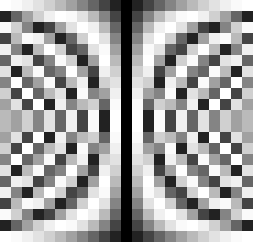
These eigenvalues can be precomputed, since they depend purely on the set of finite angles of the missing projections as given by Prop. 4. The form of the DFT eigenvalues are shown in part (b) of Fig. 10 and Fig. 3 for .
Thus, the 1D Ghost convolution approach may be used to generate a 2D Ghost as follows:
-
1.
Pre-compute the Ghost operator eigenvalues via the DFT. This can be used as a hash table to pick out the relevant operator based on the projection being convolved.
-
2.
Convolve a delta function with each of the 2PSEs by selecting the correct eigenvalues for each operator using the eigenvalues hash table (as given by previous step) via Eq. (15) and multiplying these operators with the eigenvalues of the delta function.
-
3.
Inverse DFT to obtain the Ghost structure in image space.
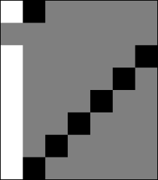
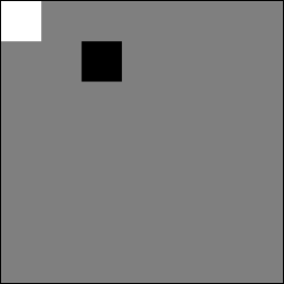
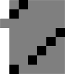
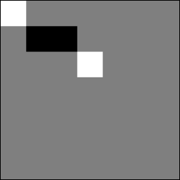
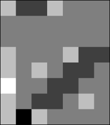
The computational complexity is for pre-computing the eigenvalues, for the 1D DFTs and for computing the convolutions. This method is advantageous when , since the computations are done only on the small number of known projections. A simple example of this construction is shown in Fig. 11 for two 2PSEs.




However, both methods are susceptible to round-off errors and loss of precision for large when utilising the DFT for the convolutions. This problem, which manifested as numerical overflow, was also encountered by Chandra et al. [14] with their method to remove Finite Ghosts. This numerical growth can be easily seen as a direct consequence of the convolutions of the eigenvalues in Fig. 3. The solution is to use the Number Theoretic Transform and the Number-Theoretic Radon Transform of Chandra [20].
II-C Number Theoretic Convolution
The Number Theoretic Transform (NTT) allows one to compute convolutions just as the DFT because the unit circle is replaced with the digital “circle”
| (16) |
so that is a multiple of , is a multiple of and [29]. The successive powers of generates a unique set of integers in some order modulo . Such a number is called the primitive root of .
The primitive root(s) in these cases have to be found by trial and error and can be computed by dividing by the prime factors of , such that , where the trial value of is prime. Integer coefficients allow computations to be done without round-off error or numerical overflow, since the results are congruent modulo [30]. A new efficient and fast algorithm for computing prime-length NTTs, that may be utilised for this work, is described in A.
Chandra [20] showed that the discrete FST still holds within the 2D NTT when placing Number Theoretic slices, i.e. the NTTs of the projections, into 2D NTT space. This allows one to replace the DFT in all computations, including those within the Ghost convolutions, with the NTT. The resulting NRT was constructed specifically to remedy the loss of precision when forming Finite Ghosts. Chandra [20] also showed that the implementation of the NTT is faster than the DFT because of its integer-only operations.
Consequently, the Ghost convolution method is impervious to numerical overflow and faster than DFT approaches. The NTT integer eigenvalues of the Ghosts kernel projections are shown in Fig. 12.
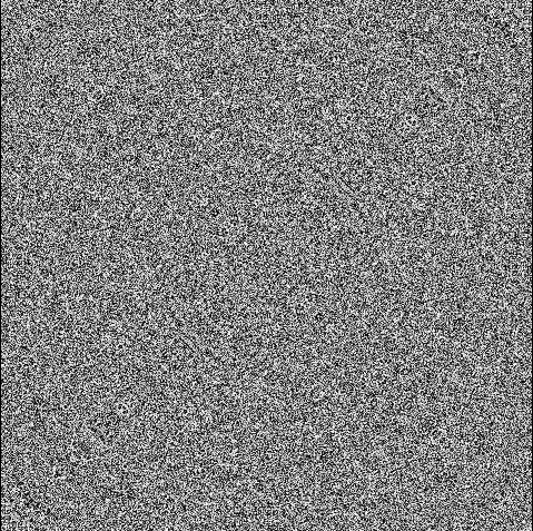
The Ghosts in this space have the value in the direction of the missing projections. An example of Ghosts within the NRT can be seen in Fig. 13.
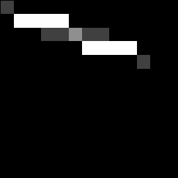
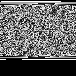
Ghosts in the NRT have another important property in that any physical or perceivable structures in the Ghosts are difficult to discern. This makes the NRT Ghosts well suited for encoding and encryption.
In summary, the advantages of the 1D Ghost convolution approach are
-
1.
Simplicity: 1D operators are simple and cyclic convolutions are much easier to compute.
-
2.
Efficiency: The majority of DRT or NRT space will be empty due to the Ghosts, so one always keeps the amount of work to a minimum.
-
3.
Speed: 1D blocks are at most elements apart in memory.
Once the Ghost is constructed/convolved, it can be used to remove the artefacts formed by the missing slices (represented via their 2PSEs) from which it is constructed. This process of de-convolution is described in the next section.
II-D Ghost De-Convolution
The Ghost convolved in the previous section may be applied as a mask to remove the Ghost introduced by missing projections in the DRT or missing slices in the DFT. The mask is applied by individually convolving each of the rows of the Ghost with the rows of the image as shown in Fig. 14.

Part (I) of Fig. 14 is effectively a sum of 1D convolutions or a sub-circulant expression given as
| (17) |
where and are circulants, denotes the Ghosted image and denotes the desired De-Ghosted sub-image. Row is back-substituted into order to make it a redundant row. Then Eq. (17) is repeated for (II) and so on. In this method, it is important to note that the shifts need to be , rather than , when convolving Ghosts to undo the right shift of the circulants. This is done by setting as the projection angle for the missing projections in the Ghost convolutions.
The coefficients of the Ghosted image and Ghost structure need only be computed once and the remaining computations done in DFT or NTT space. Thus, the computational complexity of this de-convolution method is . Note also that the de-convolution requires a total of rows, with of those rows being redundant, to function.
A visual interpretation to constructing Ghosts, that unifies the Ghost Recovery algorithm of Chandra [14] and the 2D convolution approach of this paper, can be made using -gons. See the thesis of Chandra [31] for initial work on this topic.
More work has to be done with both methods when DFT space has noise or inconsistencies present as these also become convolved during the De-Ghost process. The convolution approach requires a very good estimation of noise prior to De-Ghosting, so that the estimates may be used to de-convolve their effects on the results. Further work needs to be done in generalising the convolution approach to arbitrary missing discrete Fourier coefficients using the theory outlined in this work. Recent work by Svalbe et al. [32] discussed the minimal extent of Finite Ghosts, which may prove useful in this endeavour. In the next section, the De-Ghost method is applied to the discrete inverse problem of determining a reconstruction from a set of rational angle aperiodic projections.
III Discrete Reconstruction
Chandra et al. [14] utilised their Ghost removal technique to reconstruct an image from a limited angle set of discrete 1D projections. The term limited angle refers to the fact that the coverage of the half-plane need not be uniform and/or complete. Recent work done by Chandra et al. [18] has been done in improving the use of the discrete projection data within the DFT for fast reconstruction. However, the angle set utilised in [18] covered the half-plane. In this section, the De-Ghost method will be used to extend the work of Chandra et al. [18] to include any limited angle set of projections and reducing the total number of unique projections (for an exact reconstruction) to for a image.
For a image in a space, a total of projections need to be taken because one needs redundant rows in the image for missing slices. This means that there must be number of projections so that , since there are total number of slices. The rational angle projection geometry is known as the Mojette Transform (MT). Fig. 15 shows a simple example of a MT for a image using three projections.

III-A Ghost Angle Sets
Chandra et al. [18] showed that the MT projection set directly and efficiently maps to a prime-sized DFT space exactly as
| (18) |
where is the multiplicative inverse of that can be computed easily via the Extended Euclidean algorithm. For the dyadic or power of two case, extra projections are needed (see Chandra [20]), which are mapped as
| (19) |
when the , Positive values represent the first octant of the half-plane with the other octants produced by and [34]. The reconstruction is then obtained with a computational complexity of with , which is the same order as the 2D FFT.
The same mapping can be used to cover a fraction of the half-plane by limiting the number of octants used within the projection set. One then obtains a set that is limited, but covers DFT space fully because there exists a multiplicity of possible rational vectors for each finite angle . This multiplicity is shown as graphs in Fig. 16 for the case of a quadrant and a half-plane.


One may observe that the multiplicity is relatively “flat” in a discrete sense, but with small variations. Graph 16(a) is reminiscent of curves obtained by Svalbe and Kingston [35] when observing the “unevenness” of the rational vectors from uniform coverage. The unevenness of the Farey vectors is related to the distribution of prime numbers and the Riemann Hypothesis [36, 37].
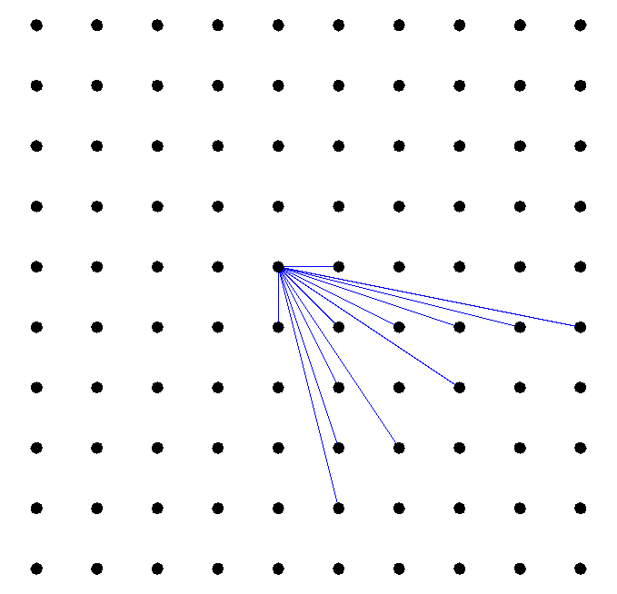
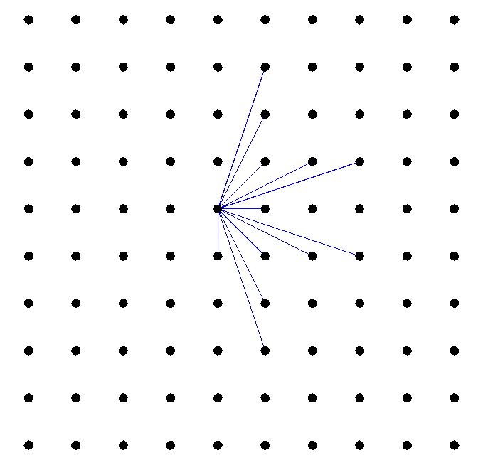
The theory of Finite Ghosts allows one to reduce the number of projections required to , rather than a total , for these limited angle sets by choosing the projections with a desired property, such as the ones with the smallest number of bins. An example of such projection sets are given in Fig. 17.
III-B Results
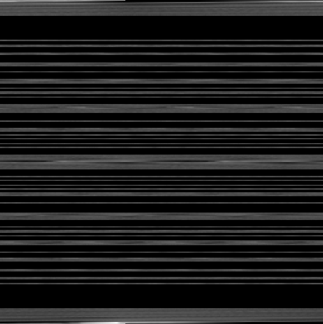
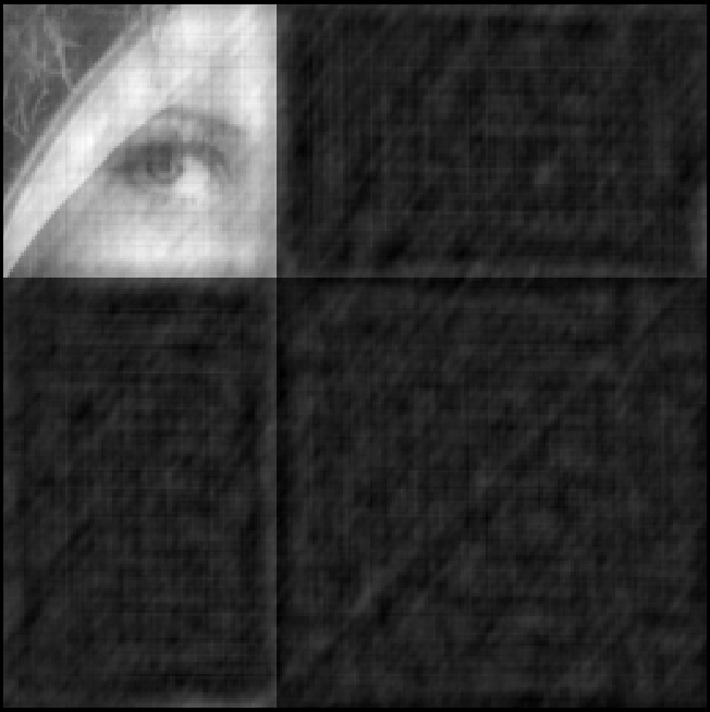
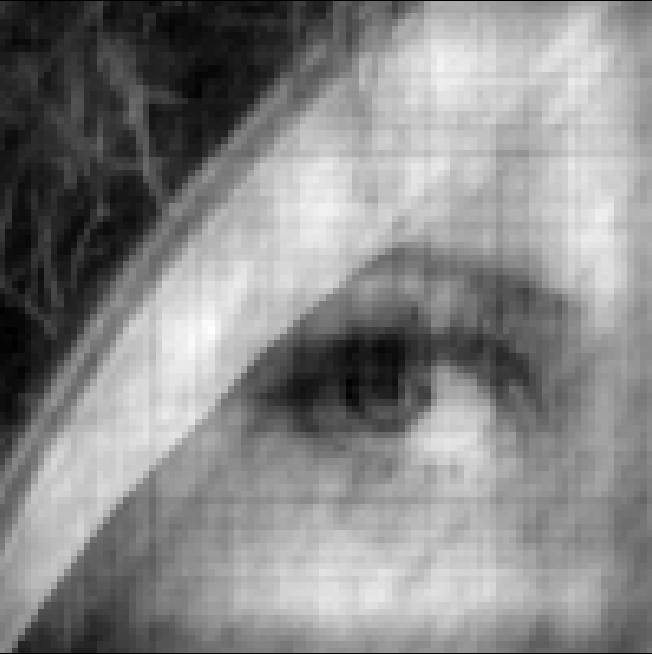
Let us consider a image of Lena and 101 rational angle projections similar to the geometry of Fig. 17(b). Also, for performance, let , so that is a power of two (see A). Therefore, from the 101 projections, there will be 156 Ghosts to remove and also 156 redundant rows in the image, so that the De-Ghost method can be applied.
Fig. 18(a) shows the DRT space resulting from 101 rational projections acquired across the half-plane and mapped via Eq. (18). Fig. 18(b) and (c) show the resulting Ghosts superimposed on the reconstruction due to the missing projections in (a). Fig. 18(d) shows the NTT Ghost eigenvalues that are used to construct the de-convolution Ghost in Fig. 18(e). Fig. 18(f) shows the final result of the De-Ghosting, which is an exact reconstruction.


The computation time was approximately 500 milliseconds on a 1.6 GHz AMD™ Turion™ 64-bit Laptop. This fairs a few orders of magnitude better than the method of Chandra et al. [14], whose computations took in the order of hours to complete.
Further work needs to be done to handle inconsistencies within projections while utilising De-Ghosting. Also, a study of the small variations within the rational angle multiplicity may be important in understanding whether some projections are more important than others.
Conclusion
A new discrete theory of Ghosts was constructed that allowed one to describe the exact effects of missing periodic slices in the Discrete Fourier Transform (DFT). The theory was used to construct new Ghost convolution and de-convolution methods, which can be utilised in recovering missing slices in the DFT (see Figs 8 to 14 and Props 1 to 4). The methods required the use of the Number Theoretic Transform and the Number-Theoretic Radon Transform of Chandra [20] to avoid numerical overflow and other loss of precision problems. This De-Ghost method was then used to solve the discrete inverse problem of reconstructing from limited rational angle projections (see Figs 17 and 18). This solution has a computational complexity of with and results in an exact reconstruction. A brief study of the limited angle set was also made (see Graphs in Fig. 16).
Acknowledgements
S. Chandra would like to thank the Faculty of Science, Monash University for a Ph.D scholarship and a publications award. N. Normand would like to thank the Australian Research Council for his International Fellowship (ARC LX 0989907).
Appendix A Fast Prime-Length Number Theoretic Transforms
For a prime-length , the NTT can be computed by first selecting the modulus as . This allows the power of in Eq. (16) to be a multiple of . For example, the modulus for the prime-length is 607 with . Then Rader’s [38] can be used to compute its fast form.
Rader [38] constructed a Fast DFT algorithm for prime-length DFTs by turning them into cyclic convolutions of composite lengths. This is achieved by permuting the input vector so that the Transform matrix becomes a circulant matrix . The algorithm is computed by handling the DC term separately and then applying the following four steps:
-
1.
Compute the primitive root for the length .
-
2.
Determine the new order of the elements of the input vector , where is given by .
-
3.
Determine the unique row of , the circulant form of . This row is given by .
-
4.
If is not highly composite, determine a power of two . Create a new sequence of this length and pad it with zeros between the first and second elements of the vector. Create of length by repeating the sequence of .
An example of the circulant form , as a sub-matrix, is given in Eq. (30) for and .
| (30) |
The zeros in the above matrices are present because the DC term is computed separately and the first element of the input vector is added to the result after the convolution. The rest of the transform is completed as the following:
- 1.
-
2.
Multiply the eigenvalues to determine the eigenvalues of the convolution.
-
3.
Inverse NTT the convolution eigenvalues to determine the convolution.
-
4.
Normalise the convolution by using the multiplicative inverse so that .
-
5.
Add the first element of to each coefficient of the transform result.
-
6.
Compute the DC term by summing all terms of the input vector and placing this as the coefficient of the transformed result .
-
7.
Extract the rest of the coefficients of for of the prime-length transform elements by using from the normalised convolution.
-
8.
Normalise the result by p if desired using multiplicative inverse so that .
The implementation of this transform can be found in the Finite Transform Library (FTL) library [40].
References
- [1] A. C. Kak, M. Slaney, Principles of Computerized Tomographic Imaging, Society of Industrial and Applied Mathematics, 2001.
- [2] J. W. Cooley, J. W. Tukey, An Algorithm for the Machine Calculation of Complex Fourier Series, Mathematics of Computation 19 (90) (1965) 297–301. doi:10.2307/2003354.
- [3] B. F. Logan, The uncertainty principle in reconstructing functions from projections, Duke Mathematical Journal 42 (4) (1975) 661–706.
- [4] K. T. Smith, D. C. Solmon, S. L. Wagner, Practical and mathematical aspects of the problem of reconstructing objects from radiographs, Bulletin of the American Mathematical Society 83 (6) (1977) 1227–1270.
- [5] D. Gottleib, B. Gustafsson, P. Forssen, On the direct Fourier method for computer tomography, Medical Imaging, IEEE Transactions on 19 (3) (2000) 223–232. doi:10.1109/42.845180.
- [6] J. Waldén, Analysis of the direct Fourier method for computer tomography, Medical Imaging, IEEE Transactions on 19 (3) (2000) 211–222. doi:10.1109/42.845179.
- [7] R. N. Bracewell, J. A. Roberts, Aerial Smoothing in Radio Astronomy, Australian Journal of Physics 7 (1954) 615–640.
- [8] M. Katz, Questions of Uniqueness and Resolution in Reconstruction from Projections, Lecture Notes in Biomathematics, Springer-Verlag, 1977.
- [9] A. K. Louis, Ghosts in tomography - the null space of the Radon transform, Mathematical Methods in the Applied Sciences 3 (1981) 1–10. doi:10.1002/mma.1670030102.
- [10] E. Candès, J. Romberg, T. Tao, Robust uncertainty principles: exact signal reconstruction from highly incomplete frequency information, Information Theory, IEEE Transactions on 52 (2) (2006) 489–509. doi:10.1109/TIT.2005.862083.
- [11] G. T. Herman, A. Kuba, Discrete tomography: foundations, algorithms, and applications, Birkhäuser, 1999.
- [12] N. Normand, I. D. Svalbe, B. Parrein, A. M. Kingston, Erasure coding with the finite Radon transform, in: IEEE Wireless Communications & Networking Conference, Sydney, 2010.
- [13] N. Normand, J.-P. Guédon, O. Philippe, D. Barba, Controlled redundancy for image coding and high-speed transmission, Proc. of the SPIE - The International Society for Optical Engineering 2727 (1996) 1070–1081.
- [14] S. S. Chandra, I. Svalbe, J.-P. Guédon, An exact, non-iterative Mojette inversion technique utilising ghosts, in: Lecture Notes in Computer Science (LNCS), Vol. 4992, Springer Berlin / Heidelberg, 2008, pp. 401–412.
- [15] S. S. Chandra, I. Svalbe, A method for removing cyclic artefacts in discrete tomography using Latin squares, 19th International Conference on Pattern Recognition (2008) 1–4doi:10.1109/ICPR.2008.4761615.
- [16] A. Grigoryan, Method of paired transforms for reconstruction of images from projections: discrete model, Image Processing, IEEE Transactions on 12 (9) (2003) 985–994. doi:10.1109/TIP.2003.816017.
- [17] T. Hsung, D. Lun, W.-C. Siu, The discrete periodic Radon transform, Signal Processing, IEEE Transactions on 44 (10) (1996) 2651–2657. doi:10.1109/78.539055.
- [18] S. S. Chandra, N. Normand, A. Kingston, J.-P. Guédon, I. Svalbe, Fast Mojette Transform for Discrete Tomography, Elsevier Signal Processing Submitted June (in Review), Available on arXiv.org, arXiv:1006.1965v1 [physics.med-ph].
- [19] S. S. Chandra, I. Svalbe, A Fast Number Theoretic Finite Radon Transform, Proceedings of the Digital Image Computing Techniques and Applications Melbourne. doi:10.1109/DICTA.2009.67.
- [20] S. S. Chandra, Exact image representation via a Number-Theoretic Radon Transform, IET Computer Vision In Peer Review, submitted April.
- [21] P. J. Davis, Circulant Matrices, John Wiley & Sons, 1979.
- [22] A. Grigoryan, New algorithms for calculating the discrete Fourier transforms, J. Vichislit. Matem. i Mat. Fiziki 25 (9) (1986) 1407–1412.
- [23] E. D. Bolker, The Finite Radon Transform, Contemporary Mathematics (American Mathematical Society) 63 (1987) 27–49.
- [24] I. Gertner, A new efficient algorithm to compute the two-dimensional discrete Fourier transform, Acoustics, Speech and Signal Processing, IEEE Transactions on 36 (7) (1988) 1036–1050. doi:10.1109/29.1627.
- [25] J. A. Fill, The Radon Transform on , SIAM Journal on Discrete Mathematics 2 (2) (1989) 262–283. doi:10.1137/0402023.
- [26] F. Matúš, J. Flusser, Image Representation via a Finite Radon Transform, Pattern Analysis and Machine Intelligence, IEEE Transactions on 15 (10) (1993) 996–1006. doi:10.1109/34.254058.
- [27] M. Do, M. Vetterli, The Finite Ridgelet Transform for image representation, Image Processing, IEEE Transactions on 12 (1) (2003) 16–28. doi:10.1109/TIP.2002.806252.
- [28] P. Soille, Morphological Image Analysis, 2nd Edition, Springer-Verlag, 2003.
- [29] J. M. Pollard, The Fast Fourier Transform in a Finite Field, Mathematics of Computation 25 (114) (1971) 365–374.
- [30] H. J. Nussbaumer, Overflow detection in the computation of convolutions by some number theoretic transforms, Acoustics, Speech and Signal Processing, IEEE Transactions on 26 (1) (1978) 108–109.
- [31] S. S. Chandra, Circulant Theory of the Radon Transform, Ph.D. thesis, School of Physics, Monash University (2010).
- [32] I. Svalbe, N. Normand, N. Nazareth, S. Chandra, On constructing minimal ghosts, APRS Conference, DICTA 2010 Accepted for presentation (2010) 1–3 December.
- [33] N. Normand, A. Kingston, P. Évenou, A geometry driven reconstruction algorithm for the Mojette transform, in: Lecture Notes in Computer Science (LNCS), Vol. 4245, Springer Berlin / Heidelberg, 2006, pp. 122–133.
- [34] I. Svalbe, Exact, scaled image rotation using the Finite Radon Transform, Pattern Recognition Letters In Press. doi:10.1016/j.patrec.2010.06.015.
- [35] I. Svalbe, A. Kingston, On correcting the unevenness of angle distributions arising from integer ratios lying in restricted portions of the Farey plane, Combinatorial Image Analysis. 10th International Workshop, IWCIA 2004. Proceedings (LNCS) 3322 (2004) 110–121.
- [36] J. Franel, Les suites de farey et le probléme des nombres premiers, Gottinger Nachr (1924) 191 201.
- [37] E. Landau, Bemerkungen zu der vorstehenden abhandlung von herrn franel, Göttinger Nachr (1924) 202–206.
- [38] C. M. Rader, Discrete Fourier transforms when the number of data samples is prime, Proceedings of the IEEE 56 (6) (1968) 1107–1108.
- [39] R. Agarwal, C. Burrus, Fast convolution using Fermat number transforms with applications to digital filtering, Acoustics, Speech and Signal Processing, IEEE Transactions on 22 (2) (1974) 87–97.
-
[40]
S. S. Chandra, The Finite
Transform Library (FTL) featuring the NTTW library, C/C++ Library
(Open Source under GPL v3) 1.0, Monash University, Australia, Available at
SourceForge.net (2009).
URL http://finitetransform.sourceforge.net