Modification of the Radiation of a Luminescent dye embedded in a finite one-dimensional Photonic Crystal
Abstract
A numerical modeling of the radiation emitted from a Luminescent dye embedded in a finite one-dimensional photonic crystal is presented. The Photonic Band Structure and the Photonic Density of States are derived using classical electromagnetic approach, and the Finite Difference Time-Domain formalism is used to calculate the electromagnetic field distribution. It is found that the periodic modulation provides an effective way to control the Spontaneous Emission under certain circumstances. We find the conditions where a large amount of light can be enhanced on the vicinity of a photonic band edge due to the presence of a high density of states. This phenomena opens the possibility to design new Lasers sources.
pacs:
Valid PACS appear hereIt is a long known fact that the Spontaneous Emission (SE) is not an immutable property of the source but can be altered by the environment in which the atom is situated PhysRev.69.37. The SE in a periodic medium such as a Photonic Crystal (PC) leads to many effects not present on unbounded media PhysRevA.53.2799. In particular, the modification of the radiation of a Luminescent dye embedded in a PC has been verified in many experiments.polman:1; 802983; 802996 This phenomenon has considerable consequences in both, Science and Technology ISI:000279963000001. In Science, because SE is a Quantum phenomenon effect that can be now study not only in relation to the existence of Photonic Band Gaps (PBG) -frequency ranges in which no propagating modes exist- but also within the interaction of more sophisticated phenomenas such as nonlinearities PhysRevLett.58.2059; kita:161108, cavity interactions 1367-2630-12-5-053005, etc. For Technology, because a monochromatic enhancement of the emitted light opens the possibility to design new Laser sources zhao:063103.
The SE have been explained by Classical and Quantum Electrodynamic approaches. PhysRevA.53.2799. The Classical Electrodynamics approach study the SE in terms of the deformation of the radiation field of a dipole due to the multiple interferences of a periodic infinite media. PhysRevE.72.056609. The Quantum Electrodynamics describes the SE as a formalism based on the restriction of discrete electromagnetic field values when modeling it, and at first-order perturbation theory the emission rate can be calculated using Fermi’s golden rule PhysRevA.41.2668. In both approximations the formulation is based on the unrealistic consideration of an infinite crystal. A practical realization of SE on PC is inevitably of finite size, however. On the other hand, the consideration of an dipole as the source of radiation is also unrealistic. Dipolar radiation produces radiation with an intrinsic spatial distribution that does not occur on Luminescence experiments.PhysRevE.68.036608 The luminescent dye as a source of electromagnetic field is more likely to a Gaussian source with a central field frequency than the radiation field of a dipole.PhysRevE.72.017601 One has to note that that all kind of approximations, Classical or from Quantum theory have to establish its connection with the experimental conditions. In this case, the more suitable experiment to understand the Luminescence in presence of PBG materials is to study the SE modification of a Gaussian source immersed in a finite PC.
The PBG materials are periodic structures which do not allow propagation of photons over a finite band of frequencies PhysRevLett.58.2059. A one-dimensional (1D) PBG structure is the simplest PC and usually is called Bragg Reflector when restricted to a quarter-wave stack.Garmire:03 1D-PBG structures have interesting effects as anomalous group velocity SV_21_18 and dispersion RMF_54_95, existence of giant PBG JEMWA_24_351; PIER_111_105 and the tunable control of the band gap edges PhysRevB.72.035336; manzanares-martinez:101110.
The control of fluorescence have been predicted on several PBG PhysRevA.65.043808. In the present study, we investigate the change on the emitted power spectra due to the placement of a Luminescent dye within a finite 1D-PC. We have recently considered this problem theoretically to determine the degree of tuning of lasing due to the variation of the ambient condition in a liquid crystal based PC JEMWA_24_1867. The enhancement and suppression of the spontaneous emission have also been predicted and experimentally verified in higher dimensional PBG structures ursaki:1001; gaponik:1029.
In this work, we perform numerical modeling by using the Finite Difference Time-Domain method (FDTD) which is a methodology closer to the experimental conditions than the analytical formulations PhysRevA.41.2668; PhysRevE.72.056609. We solve numerically the Maxwell equations using FDTD simulations performed by Meep, a freely available software package.meep This approach is flexible and also opens the possibility to account of defects or surface states PhysRevB.66.113101.
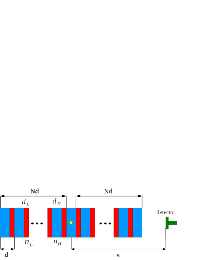
The geometry of the problem is shown in Fig. 1. A Gaussian source is embedded in a finite multilayer composed by alternative layers of high () and low () refractive indices illustrated in blue and red, respectively. The thickness of the slabs of high and low refractive indices are and . The period of the structure of the unit cell is . The layers stacks above and below the source have an identical number of periods. The total thickness of the structure is . In the direction of the periodicity a detector is placed a distance from the source.
The dispersion relation of an infinite 1D-PC is obtained using a well known formula Yariv:77
| (1) |
where is the Bloch wave vector, and and are the wave vectors for the high and low dielectric media, respectively. It is expected that the radiation of the Luminescent dye embedded in the 1D-PC can be related to the Density of States (DOS) which is defined as . is obtained by differentiating the dispersion relation in the form PhysRevA.46.612
| (2) |
The DOS is the number of allowed states and is obtained taking the relation between the number of modes available for photons within the frequency .
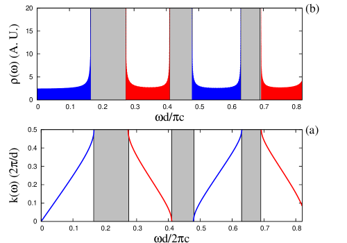
A particular case of the relation dispersion and DOS is shown in Fig. 2 in panels (a) and (b), respectively. We take the values of the indices as and . The width of the layers are and . We observe in panel (a) the existence of four bands and three PBG. It has been reported by Joannopoulous et al. that the bands can be distinguished by where the power of the modes lies PC_Joannopoulous. The energy of the bands can be concentrate in the high index media or in the low index media. For this reason we refer to ”high dielectric band” and ”low dielectric bands”. A similar situation exist in electronic band structure of semiconductors where are defined the ”conduction” and ”valence” bands PhysRevLett.67.3380. We present in blue color the first and the third bands which are related to electromagnetic modes located in the the high index media. In the same manner, the second and the fourth bands are related to a electromagnetic mode located in the low index media. In panel (b) we present the DOS for each band that is obtained from the derivative of the relation dispersion using eq. (2). We observe an high value of the DOS at all the band edges. For clarity, we present in gray color all the PBG regions.
The SE a Luminescent dye located in the center of the finite 1D-PC is modeled as a Gaussian source for the electric field () in the form PhysRevE.72.017601
| (3) |
where and are the central frecuency and width of the pulse, respectively.
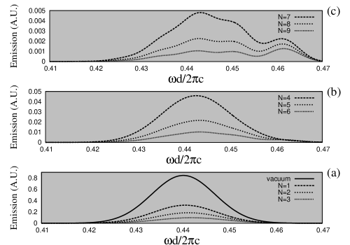
The SE of a Gaussian source embedded in a Finite 1D-PC are displayed in Fig. 3. We consider that the source have a central frequency of and , respectively. In panel (a) we present as a reference the case of the emission in the vacuum with a solid line. We also present the cases of . In panels (b) and (c) we present the emission for and . We observe that as we increases the number of layers, the SE decreases. This is the expected results because the source is emitting in the PBG.
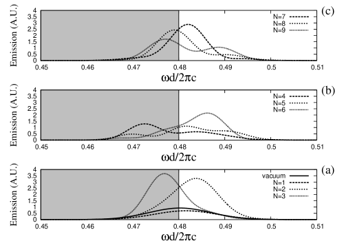
In Fig. 4 we present the cases of the SE at the high energy limit of the band gap. We take a central frequency and pulse width of and , respectively. We observe in panel (a) that the SE for the case of the vacuum and is almost similar, but it exist a dramatic enhancement of the radiation for . This is result of a redistribution of the electromagnetic radiation induced by the existence of allowed Bloch modes. This preferential distribution of the electromagnetic field in the periodicity direction is similar in panels (b)and (c).
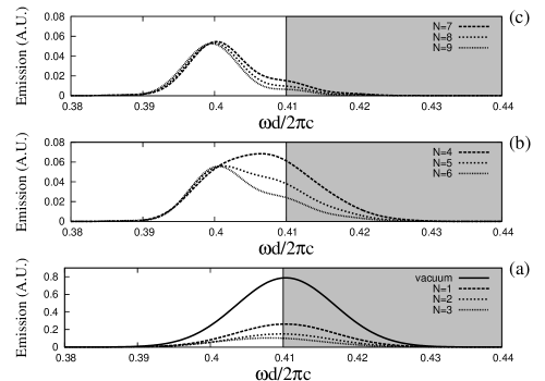
The SE emission at the low energy limit of the band gap is presented in Fig. 5. Here we consider the values and ,respectively. In difference to the case of the high energy limit, here we do not observe an enhancement of the radiation measured by the detector, as it could be expected by the presence of the band gap edge. We observe in panel (a) a decreasing in the radiation. In panels (b) and (c) we observe a kind of stabilization of the radiated power.
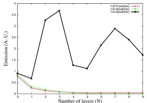
A global vision of the emitted radiation for the tree cases can be observed in Fig. 6. For the cases of the emission at the middle of the PBG () and at the lower band edge (), we observe an important decreasing of the emission. In contrast, at the upper PBG () we observe a high enhancement of the radiation. However, it is strange the low coupling of the electromagnetic field at the low energy limit of the band gap. Why the electromagnetic field is not coupled with this band?
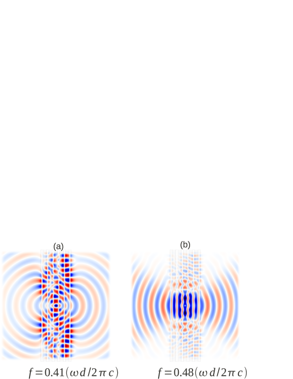
In order to explain this difference, we show in Fig. 7 the electromagnetic field produced at the low () and high () band edges in panels (a) and (b), respectively. We observe that in panel (a) exist a complicate mode, where a destructive interference exist that does not allow the excitation of the low index mode. In contrast, in panel (b) we observe that the high index mode is excited. The reason of this difference is that the source of electromagnetic field is placed at the high index material.
In conclusion, we have presented a numerical modeling of the emission of a Luminescent dye embedded in a finite 1D-PC. The treatment allows us to understand that is possible the enhancement of the radiation at the high energy limit of the band gap. We have also demonstrated that the DOS can not be directly related to an enhancement of the emitted power because it is necessary to take into account the conditions of coupling between the radiation of the source to the allowed Bloch modes at the band edge.
I Acknowledges
PCG thanks the Optical Academy of the Department for Physics Research of the Sonora University for a temporary contract as Research Associate.