A New Noncoherent Decoder for Wireless Network Coding
Abstract
This work deals with the decoding aspect of wireless network coding in the canonical two-way relay
channel where two senders exchange messages via a common relay and they receive the mixture of two
messages. One of the recent works on wireless network coding was well explained by Katti
et al. in SIGCOMM’07. In this work, we analyze the issue with one of their decoders when
minimum-shift keying (MSK) is employed as the modulation format, and propose a new noncoherent
decoder in the presence of two interfering signals.
Index terms: network coding, wireless networks, cooperative transmission, relay network.
I Introduction
Before the benefits of coding for networking were recognized, wireless networks were designed to protect packets from interference. Interference was considered a factor which has only negative effects on network systems. However, network coding [1] in the wireless context, termed analog network coding (ANC) [2] or physical-layer network coding (PNC) [3], breaks this concept. Rather, intended interference is encouraged at the relays for high throughput. The main idea of network coding is that information, not packets, is the factor to be sent to a destination. It means that although packets may collide, there is no problem if the information, which each destination wants to receive, can be obtained. For this reason, network throughput can be increased by sending collided messages instead of transmitting messages separately.
This work deals with ANC introduced by Katti et al. [2]. In ANC, analog signals, which are generally represented as complex numbers, are mixed at the router instead of bits. By combining two analog signals simultaneously at the relay located in the middle of two senders, the interfered signal is forwarded to two transmitters. Two noncoherent decoders were proposed in [2]. In one of them the amplitude may be estimated directly from a signal clear of interference: we refer to it as the direct method. The other decoder estimates amplitudes from interfered signals: we refer to it as the joint method. The former decoder is noisier than the latter. However, we believe the joint method was not used when it came to implementation; rather, they obtained amplitudes from the free interference part [4].
In this paper, we first analyze the issue of the joint method. It turns out that the joint method has difficulty in estimating the amplitudes when minimum-shift keying (MSK) was employed as the modulation format. We then propose a new method of joint estimation of the signal amplitudes. Other parts of our decoder are the same as [2], and our decoder has almost the same error performance as the direct method.
Several improved algorithms avoiding coherent demodulation have been introduced. A decoder for frequency-shift keying (FSK) systems is introduced in [5] which requires a larger signal-to-noise ration (SNR) for the same throughput compared with the counterpart. The noncoherent decoders in [6, 7] assumed the knowledge of average received energies or the statistics of channel attenuation. This work, however, makes no such assumptions; instead, it obtains received energy from the interference signal.
II Illustrating example and system model
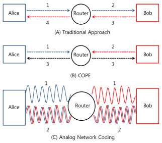
Consider the canonical 2-way relay network which is well known as Alice-Bob topology and only one packet is allowed to be sent at once. When Alice and Bob want to exchange a pair of packets through a relay as Fig. 1 shows, total 4 time slots are used for the traditional approach. Alice sends a message to the router and the router forwards it to Bob. The process of Bob is also similar to Alice’s process. By digital network coding [8], total time slots can be reduced to 3. Alice sends a packet and Bob sends a packet sequentially then the router XORs the two packets and forwards it to both destinations. By XORing with their own packet, Alice and Bob can obtain the packet which they want to receive. Interestingly, total time slot can be reduced to 2 by ANC [2]. Two senders transmit the packets simultaneously. If Alice and Bob can decode what they want to receive from the collided packet, the throughput can be increased.
ANC proposed in [2] uses the MSK modulation. In order to understand how ANC works, a brief instruction about the modulation and the form of the signal at both sender and receiver side will be given.
II-A The transmitter side
In the baseband equivalent model, a wireless signal is represented as a complex number which has a phase and an amplitude and is a discrete-time function. In this sense, the transmitted signal from the sender takes the form
where the subscript means sender side. We need to map “0” and “1” to two different forms of complex functions.
The MSK modulation uses a phase difference between consecutive complex samples to distinguish bits. When the next bit is “1” then gives a phase difference comparing with the previous one while a phase difference of represents “0”.
II-B The receiver side
What we are interested in is how the received signal looks like under the condition which the channel is quasi-static flat-fading. An amplitude and a phase in the transmitted signal are different from those of the received signal due to channel attenuation and a phase shift. When the transmitted signal is , we can represent the received signal as
where is channel attenuation and is a phase shift which varies according to the distance between the sender and the receiver.
Although there is a fading, the decoding for the MSK is simple. When we map the received complex samples back into the bit stream in MSK, the phase difference between consecutive complex samples decides whether the bit is “0” or “1”. The amplitude for the MSK is constant so consecutive complex samples look like and . In the noiseless case, simply we can know the phase difference between consecutive samples by
For that reason, if the angle of is then we map it to “1” and to “0”. However, in practice, the angle of complex number is not exactly or since there are channel noise and estimation errors. Therefore, if the phase difference is greater than 0 then it is mapped to “1” and if the phase difference is negative then it denotes “0”.
III Analysis of Existing Decoder
The received signal at a destination is the sum of Alice and Bob’s signals after amplifying by the router. However, the interfered signal is not the exactly same as the sum of two signals which Alice and Bob sent. The reason is that two transmitted signals experience the channel from each sender to the router and the channel from the router to the corresponding receiver. As a result, the signal that they receive is [2]:
where and refer to the phase of the signal transmitted by Alice and Bob, respectively, whereas and are the amplitudes.
The simple decoding is that Alice estimates the channel parameters , and then creates the version of her own signal and subtract it from the received signal. The remainder is which Alice can decode by the standard MSK demodulation. However, this technique suffers a few drawbacks. It incurs overhead, especially when the channel is time varying; also, estimating phase shift is not simple and requires accurate coherent phase tracking.
In [2], there is a two-step process introduced to calculate phase differences when two signals interfere. In order to make it simple, let the representation of the received signal be :
| (1) |
where , and .
III-A Possible phases
It is not straightforward for Alice to tell the exact values of and just by
analyzing the interfered signal. However, once she knows the amplitudes, and , then she can calculate
possible values of and by the following lemma proved in [9, 10].
LEMMA 1. If is a complex number satisfying (1), then the pair takes one of the following two pairs [2].
| (2) |
| (3) |
where , and is the angle of the complex number.
For each solution to , there is a unique solution for . For instance, if , then . Accordingly, the lemma gives two pair of solutions.
III-B Existing method to estimate amplitude A and B
In order to obtain possible phase pairs using the Lemma 1, two equations were introduced in [2].
The energy of the interfered signal is
| (4) |
where is the expectation. If the input bits are random, will be 0. For this reason, the input bits were XORed with a pseudo-random sequence before the modulation and then XORed again at the receiver to get original bits in [2]. Therefore, the first equation can be reduced to
| (5) |
Alice can estimate by observing the average energy in the received signal. The second equation comes from the variance of the received signal. Alice can calculate the following quantity [2]:
| (6) |
The value for was shown to be [2]
| (7) |
From the two equations, Alice can estimate two amplitudes.
However, we realize that, in the case of MSK modulation, the value for cannot be reduced to (7). The reason is as follows.
The value means the average energy calculated from the received complex samples that is greater than mean value. By (4), we can rewrite as
If one took the average of a cosine over its positive lobes, would be reduced as . But this is not true in the case of MSK modulation because the phases can only take discrete values.
Let be the initial angle between two vectors. There are 4 possible pairs for the next interfered sample. If the next bit for Alice and Bob is the same like 1 and 1 or 0 and 0, the phase for the two vectors will shift to the same way, or . It means that does not change when the next bits for two signals are the same. If Alice’s next bit is 1 and Bob’s next bit is 0 then will change to . when Alice’s next bit is 0 and Bob’s next bit is 1 then will change to . That is what we can make all the possible angles in the next interfered sample. However the values for and are the same (i.e., ). Hence, there are only two possibilities for the value of a cosine, or . Therefore, if is positive, ; if is negative, . This pattern is repeated during the same packet. That is, there is a fixed value
| (8) |
and therefore
| (9) |
throughout the same packet and it will not be changed until the next packet. Therefore, in general (7) does not hold within a given packet for MSK modulation111One might wonder if (7) could hold true by averaging over many packets (such that the angle will be truely random on ). However, this does not work since the amplitudes will also change from packet to packet due to fading..
Moreover, even if we assume that (7) were right, there is still an ambiguity which amplitude is for Alice. This is because (5) and (7) are completely symmetric with respect to and . Without extra information we cannot distinguish which amplitude is for Alice. If we apply the wrong amplitude to Alice, it will cause a problem.
Consider the equations (2) and (3), which are used to obtain possible phases. If we exchange and , the equation for is changed to the equation for . That is, if we apply wrong amplitude to Alice, it will cause a problem where Alice would align her known phase difference with the phase difference for Bob. Therefore, Alice has to distinguish the amplitude for her signal.
For these reasons, we need a new method to estimate the amplitudes222When it was presented at the SIGCOMM’07 conference, the joint method was not mentioned [4]..
III-C Estimating phase differences
Once Alice get two possible pairs of phases, she needs to pick right pair of phases. In [2], the way to choose right phase difference was well explained. When the two solution pairs are represented as and , Alice has the following four possible phase difference pairs [2].
| (10) |
Alice knows the phase difference of her signal and thus she uses it to pick up the right phase difference pair. Alice compares the phase difference of her signal, with the four possible phase differences using the next following equation to pick up the correct [2]:
| (11) |
Alice can determine the correct by choosing the smallest error from (11) then she finds the unique .
IV The new method to estimate amplitudes
The key point for estimating amplitudes from the interfered signal is to find the factor which changes according to the amplitudes. The answer lies in transformation of the structure in the interfered signal when angle between two signals changes from the constructive form to the destructive form or vice versa. The transformation occurs when the next bits for Alice and Bob’ signals are different. The transformation between two interfered signals contains the information about two amplitudes.
Consider Fig. 2. denotes the first vector for Alice and the second while and mean Bob’s vectors. Assume that the next bit for Alice is 1 and the next bit for Bob is 0 so that the form changes from constructive to destructive. When we look at the two groups of vectors in detail, we can find the two parallelograms which are and . In Fig. 3, the two parallelograms are described in more details; so from now we will explain the new method based on Fig. 3. If we know and , then we can calculate the length of which is the amplitude for Alice signal.

As Fig. 3 shows, and . From the received signal, we can get the angle difference between and which is . It means that we can get by .
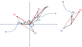
Since the diagonals of a parallelogram bisect each other, . In the same way . Now the amplitude of Alice signal is . In addition, if we represent it just using the information of the received complex samples then it can be rewritten as
| (12) |
In the same way, the amplitude for Bob’s signal is
| (13) |
The derivation is similar in other cases (e.g., the next bit for Alice is 0 and the next bit for Bob is 1). To summarize, and take values in one of the following two pairs
| (14) | |||||
| (15) |
Now, the problem is to choose which amplitude is for Alice. Since the probability that the values for A and B are the same is extremely low, Alice can obtain her amplitude if she knows whether her amplitude is greater than Bob’s one. By a known pilot bit sequence from the interference-free part, which is added at the beginning and the end of each packet to distinguish whose packet it is, Alice can align her signal with received signal through matching a known bit sequence. As a result, she knows what is the next bit for her packet.
The transformation of structure in interfered samples occurs when the next bits for Alice and Bob are different. We use that information to choose the right amplitude. Mainly there are two cases.
(1) The next bit for Alice signal is 1. If the amplitude of Alice’s signal is greater than that of Bob’s signal, the angle difference between and varies from 0 to ; otherwise it varies from to .
The reason is that the diagonal of a parallelogram is closer to the line which is greater than the other. In that sense, if the two next vectors do not cross each other when they change from the previous vectors like Fig. 2(a), the range of the angle between and is from to . If additionally the amplitude of Alice’s signal is greater than that of Bob’s signal, then the angle varies from to ; otherwise varies from to .
If the next vectors for Alice and Bob signals cross each other like Fig. 2(b), then the angle varies from 0 to degree when the amplitude of Alice’s signal is greater than Bob’s one. If the amplitude of Alice signal is less than Bob’s one, then the angle varies from to 0.
| Case | ||
|---|---|---|
| No crossing | ||
| Crossing |
Table I shows the examples for the four cases where crossing means that the vectors for A and B cross each other when their phases are moved according to the next bits. Fig. 2 in our paper shows that (a) is the no-crossing example and (b) is the crossing one.
(2) The next bit for Alice signal is 0. Similarly, when the amplitude of Alice’s signal is greater than that of Bob’s signal, the angle between and is in range from to ; otherwise it is from 0 to .
In this way, we can get values for and . If we take many transformation samples and average
and , the averaged amplitudes will be more accurate.
Now, a practical issue is how Alice detects the transformation of the interfered signal. When the transformation occurs, the energy of received signal changes from to , or vice versa, where is measured one (6). Namely, the energy difference is . Our detecting algorithm declares occurrence of the transformation of the structure when the energy difference between the previous and the current signals is greater than . Since there is some noise, the variance does not change exactly . Therefore, is a relevant threshold but the other threshold can be applied with regard to the SNR.
V Simulation Results
We have simulated it using Matlab which is commonly used for simulation in variety areas. Although Matlab is not enough to obtain a correct benefit of ANC, it can at least show whether the new approach to estimate amplitudes from the interfered signal works properly.
In this simulation, we have assumed some points. First, the interference detector described in [2] determines the interference starting point without error. Second, the first bit of 64bit length known pilot sequence, which is added for practical issue [2], is a fixed bit. Since this models flat-fading quasi-static channels, there is high probability to make a wrong decision for the first bit. Last, in [2], they have already provided that the average overlap between Alice’s packet and Bob’s packet is 80%. We just use it because it is difficult to set the size of the time slot used for random delay. In a similar sense, we have not added the header, which includes destination information.
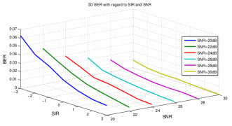
We have simulated ANC with the new method in the SNR region of dB, which is a typical range for 802.11 [11, 12]. We analyse the relationship between SNR, signal-to-interference ratio (SIR) and bit error rate (BER) at the same time for ANC. The simulation was implemented in the SNR range of from 20dB to 30dB and the SIR range of from -3dB to 3dB. The SIR is defined as,
This result in Fig. 4 shows that ANC works well even though two transmission powers are different. However, the best approach would be to use the equal transmission power for Alice and Bob’s signals. The reason is that when the SIR is 3dB so that Alice can decode received signal with the BER of around 1% which is easy to correct, Bob will face the BER of approximate 6% which is relatively high.
The result is not much different from the original result in [2]. The original result has provided that the average BER is approximate 4% and the BER varies from around 4.5% to below 1% dependent on SIR from -3dB to 3dB.
VI Concluding remarks
We have proposed a new noncoherent decoder for ANC which jointly estimates the two amplitudes from interfered MSK signals. It is of interest to extend the idea to other modulation formats and network topologies.
References
- [1] R. Ahlswede, N. Cai, S.-Y. R. Li, and R. W. Yeung, “Network information flow,” IEEE Transactions on Information Theory, vol. 46, no. 4, pp. 1204–1216, July 2000.
- [2] S. Katti, S. Gollakota, and D. Katabi, “Embracing wireless interference: Analog network coding,” SIGCOMM, Aug. 2007.
- [3] S. Zhang, S.-C. Liew, and P. P. Lam, “Physical layer network coding,” SIGCOMM, 2006.
- [4] SIGCOMM 2007, “Live broadcast and archives,” http://www.soi.wide.ad.jp/project/sigcomm2007/.
- [5] J. H. Sorensen, R. Krigslund, P. Popovski, T. K. Akino, and T. Larsen, “Physical layer network coding for FSK systems,” IEEE Communications Letters, vol. 13, no. 8, pp. 597–599, 2009.
- [6] M. C. Valenti, D. Torrieri, and T. Ferrett, “Noncoherent physicla-layer network coding using binary CPFSK modulation,” IEEE Military Communications Conference, 2009.
- [7] T. Cui, F. Gao, and C. Tellambura, “Differential modulation for two-way wireless communications: A perspective of differential network coding at the physical layer,” IEEE Transactions On Communications, vol. 57, no. 10, pp. 2977–2987, 2009.
- [8] S. Katti, H. Rahul, W. Hu, D. Katabi, M. Medard, and J. Crowcroft, “XORs in the air: Practical wireless network coding,” SIGCOMM, Sept. 2006.
- [9] S. Katti, Network Coded Wireless Architecture, Ph.D. thesis, Massachusetts Institute of Technology, 2008.
- [10] J. Hamkins, “An analytic technique to separate cochannel FM signals,” IEEE Transactions on Communications, vol. 48, no. 11, pp. 2980–2989, 2000.
- [11] J. Geier, “SNR cutoff recommendations,” http://www.wifiplanet.com/tutorials/article.php/3468771, 2005.
- [12] M. Souryal, L. Klein-Berndt, L. Miller, and N. Moayeri, “Link assessment in an indoor 802.11 network,” Proc. IEEE WCNC, 2006.