Effect of the reference electrode size on the ionization instability in the plasma sheath of a small positively biased electrode
Abstract
It is well known that additional ionization in the vicinity of a positively biased electrode immersed into a weakly ionized plasma is responsible for a hysteresis in the electrode current-voltage characteristics and the current self-oscillations rise. Here we show both experimentally and theoretically that under certain conditions these phenomena cannot be correctly interpreted once considered separately from the reference electrode current-voltage characteristics. It is shown that small electrodes can be separated into three groups according to the relation between the electrode and the reference electrode areas. Each group is characterized by its own dependence of the collected current on the bias voltage.
I Introduction
Phenomena related with a biased electrode (Langmuir probe) imbedded into a plasma have been studied beginning from the rise of plasma physics and are still in progress. The aim of the current investigation is the determination of the link between the measured current-voltage (C-V) electrode characteristics and the plasma parameters. For this purpose it is desirable to minimize the disturbances of the actual plasma parameters introduced by the probe.
However, there is a number of processes in the surrounding plasma caused by the probe presence that affect significantly the probe C-V characteristics. The probe C-V characteristics can be multi-valued and demonstrate a hysteresis-like behavior. Moreover, the current collected by the probe produces a set of instabilities (sheath-plasma instability Stenzel1 , ionization induced instabilities Klinger ; Stenzel2 , etc). As a result, the self-oscillations of the collected current rise even when the probe potential is kept constant.
There are several papers where the physical processes responsible for the excitation of the probe current oscillations are studied. However, the role of a mandatory element – the reference electrode for the probe – that closes the current circuit through the plasma, has to our knowledge not been adequately explored. In this paper the results of a detailed experimental investigation of the C-V characteristics of a positively charged probe are presented. Various probes have been studied whose area is small enough compared with the ion-collected electrode area (the reference electrode area) :
| (1) |
where and are the electron and ion masses, respectively. It will be shown that probes, whose areas meet the condition (1), can be separated into three groups: large, intermediate, and small probes. Each group is characterized by its own regime of interaction with the plasma. Affiliation with one group or another is determined by the relation between the C-V characteristics of the probe and the reference electrode which are connected in series via the plasma.
This paper is organized as follows. In section II, the experimental setup is described. The experimental results are presented in section III. A simple qualitative theoretical model and comparison with the experimental results are presented in section IV. The paper main results are summarized and discussed in section V.
II Experimental setup
The experiments were mainly performed in a stainless steel vacuum chamber, having an inner diameter of 30 cm and a height of 8 cm (Fig. 1a). This chamber was equipped with two insulated tungsten filaments, one of them had 0.3 mm diameter and the other one – 0.1 mm. Both of them could be heated separately. The first one could be moved just when the chamber was open and the other one could be moved inside the chamber during experiments. The chamber was also equipped with a large surface probe, having an area , with a comparatively small () movable single probe and with a special holder for replaceable platinum probes of various lengths (1 – 25) mm and diameters (0.05 – 5) mm. The first (thicker) filament was used as a hot cathode. It was heated when a voltage pulse of 0.2 s duration was applied per each 5 s. To obtain a hot-cathode discharge and a plasma we applied a dc voltage either between the cathode and the grounded vacuum chamber or between the cathode and the large surface probe. In the latter case the discharge circuit was floating. The plasma density and the electron temperature were derived from the C-V characteristics of the above-mentioned probes. To verify these measurements we could also use the movable probe as a resonance probe r1 . To measure the plasma potential, the thin filament was used as a hot probe. To heat it, another dc source was used. To bias the small platinum probe we used either a dc power supply or a pulsed saw-tooth or rectangular voltage with pulse duration (150 – 200) s (see Fig. 1a). Just a positive bias was used. The pulsed regime was used either to obtain its C-V characteristics in one “shot” or to prevent probe overheating if the collected current was too high. A thin glass plate of 3 cm diameter (not shown in Fig. 1a) could be placed between the hot cathode and the small positively biased probe to prevent direct current of the emitted electrons to this probe. A strong permanent magnet could be placed in various positions in the vicinity of the small probe in such a way that a magnetic field of (100 – 600) Gauss could be achieved there (see Fig. 1b). Also a set of spirals having a diameter of (5 – 20) mm and a 25 mm length could be placed around this probe (Fig. 1b). These spirals could also be biased either positively or negatively with respect to the probe. Some verifying measurements with just a hot cathode and a small probe could be carried out in a big vacuum chamber having a 66 cm diameter and a 100 cm length.
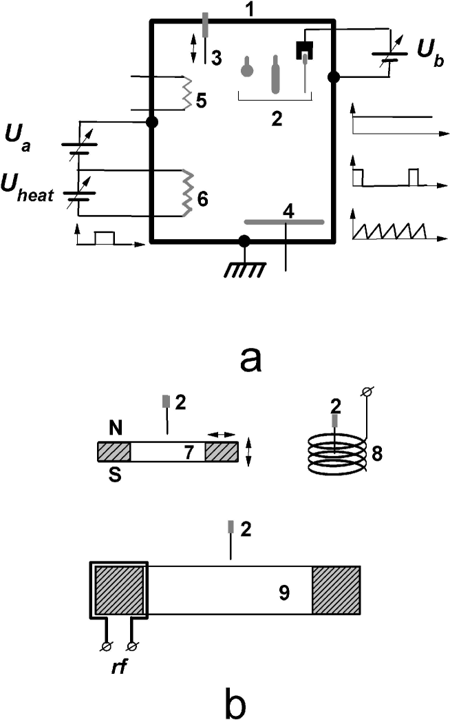
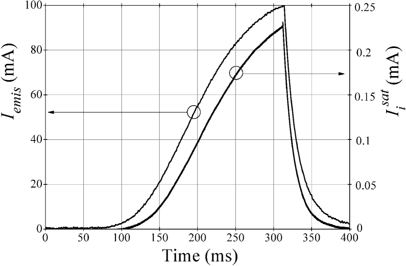
In our experiments we used either Ar at a pressure (0.5 – 5) mTorr or Xe at a pressure (0.1 – 1) mTorr. Typically we applied an anode voltage V in order to make sure that we work in a regime with the thermal limitation of the emitted current. This is reasonable in order to eliminate dependence of the plasma density on . Indeed in the range V, variations of the emitted current did not exceed 10%. On the other hand it was certain that in measurements with a large positive bias on the small probe the value of could be reduced to zero (the cathode directly connected to the chamber). In the investigated pressure range the plasma density was found to be directly proportional to the pressure and the emitted current . The waveform of the emitted current along with the ion saturation current , collected by the large surface probe, are shown in Fig. 2. The duration of the growth ( s) was long enough to consider a steady state plasma at any moment. In our experiments a 100 mA emission current corresponded to , mTorr and eV with Xe gas. For the measurements the discrepancy between the probe characteristics method and the resonance probe method did not exceed 15%. The fraction of fast electrons having energy never exceeded (1 – 2)%. They appeared as a step in the ion part of the probe characteristics r2 . The emitted current as well as the probe current were measured with small current-view resistors. In order to study the influence of the ionization level there was a possibility to insert inside the vacuum chamber a single-core ferromagnetic inductively coupled (FIC) plasma source, driven by a powerful pulsed rf oscillator r3 (see Fig. 1b). With this source the plasma density increased a few hundred times (at the same pressure) and the ionization rate could reach a value of (20 – 30)%.
III Experimental results
When the positive bias applied to any of the replaceable probes (Fig. 1a) was relatively low ( V for Xe and V for Ar) the various C-V characteristics obtained with our set of probes, along with the measured potential fall between the plasma and the probe, have already been described and explained long ago (see e.g. Ref. 7 and references therein). At a higher bias a significant deviation could appear with various combinations of the gas pressure and probe sizes. Note, that at each “shot” the plasma density increases from a very low value, when the Debye length is large and the plasma sheaths near walls and electrodes could be comparable to the chamber sizes, to a value , when becomes small compared to the smallest probes we used.
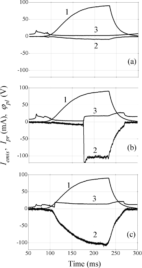
Large probe. — Thus, with the largest probe we used ( mm) and at a fixed pressure, say mTorr of Xe, the same probe characteristics could be also kept for V just with one exception. Namely at very low plasma densities some irregular oscillations appeared in the probe current (see Fig. 3a). For higher the behavior of and the potential fall between the probe and the plasma during the pulse are very similar to the previous case when was low (Fig. 3b). The maximal electron probe-collected current , saturated at high , was equal to the sum of the emitted current and the total ion saturation current to the vacuum chamber walls (Fig. 3c). The total ion saturation current to the walls was derived as the geometrical ratio of the surface probe area () and the total area of the metal vacuum chamber () multiplied by the ion saturation current to this probe (Fig. 2). In the case of the floating discharge circuit, i.e. when was applied to the large surface probe instead of the chamber wall, was simply subtracted from this sum. It should be noted that at the densities when the irregularities of appear, the measurements showed that the thickness of the plasma sheath near the surfaces become comparable to the chamber size r5 . In our case it corresponds to , mA for Xe, and mA for Ar. The pressures were 0.3 mTorr and 1 mTorr for Xe and Ar respectively. Reducing drastically – in one order of magnitude – the pressure at the same pulse of (at the same ) it was possible to obtain these irregularities during the whole pulse of . Again, if the discharge circuit was floating, the maximal amplitude of the probe current irregular perturbations became smaller at the corresponding value. While these perturbations appeared in the electron probe current , no visible changes were seen neither in the emitted current (see Fig. 3) nor in the ion saturation current collected by a movable or surface probe. The latter means that the plasma density kept constant.
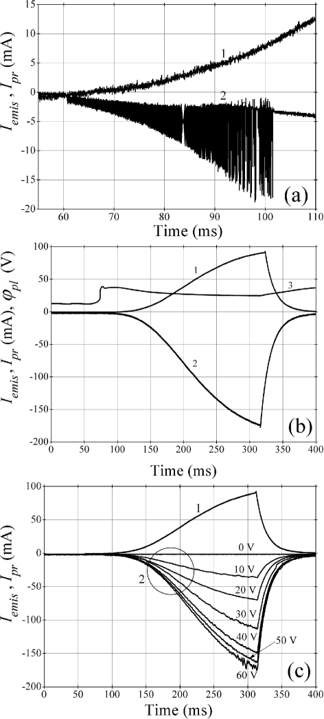
Intermediate probe. — A very different behavior of could be observed when the probe sizes were reduced to (0.6 – 1.2) mm. At very low pressures ( mTorr) the same irregular oscillations could still be seen. In the pressure range (0.1 – 0.8) mTorr for Xe, when the probe bias exceeds 25 V, but still below a certain threshold, the probe C-V characteristics appeared as a prolongation of those for the lower voltage. They could be described by the theories mentioned above r4 ; Mott . On the other hand, when the bias voltage reached a certain value, a single, few or many current spikes appeared in the probe current . After adding further (2 – 4) V, periodic spikes filled the whole plasma pulse, i.e. in the wide range of there appeared a probe-current instability. The corresponding is recognized as the threshold . Namely at V and at mTorr of Xe in the density range of the periodic spikes in the probe current are shown in Fig. 4a,c. Their period and duration kept approximately constant in the mentioned above density range and weakly depended on the bias voltage . The waveform of in combination with the potential fall between the plasma and the wall at the same , but at a bit higher V, are shown in Fig. 4b. It is interesting to note, that these periodic spike oscillations, as a rule, started from a small but finite value of , the stage with irregular oscillations was usually skipped. On the other hand, in the narrow and unstable ranges of the bias and pressure it was possible to obtain irregular oscillations at low which were switched to regular ones at higher .
These spikes were quite narrow compared to their period (see Fig. 4c). Typically the spike duration was for Ar and for Xe while the spike period was and , respectively. It should be noted that, as seen in Fig. 4c, the spikes of correspond to the minimal potential fall between the plasma and the probe: , i.e. and are in opposite phase. Also, as seen in Fig. 4d, there is a hysteresis in the probe C-V characteristics when this instability exists.
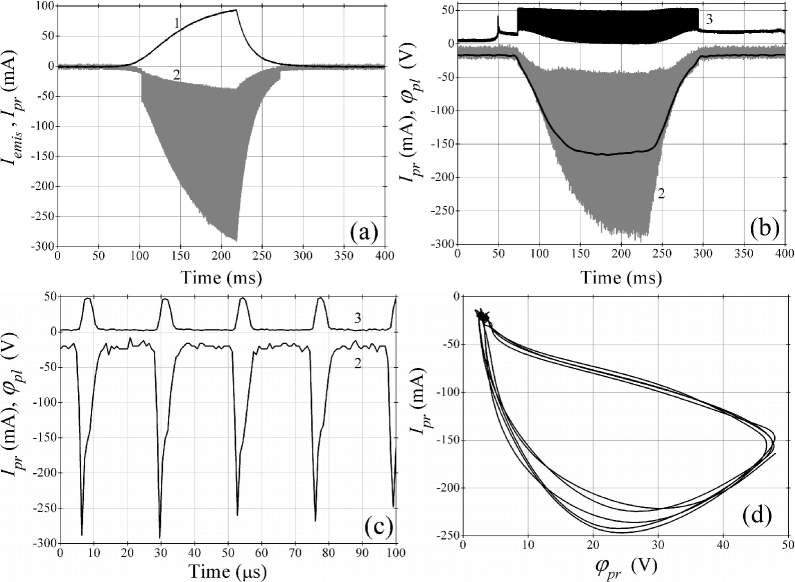
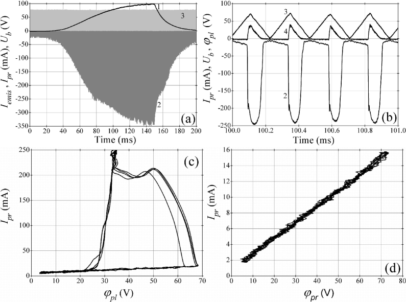
The threshold bias definitely decreased with the increase of the pressure : for Xe V at mTorr, V at mTorr and V at mTorr. A very similar tendency was obtained with Ar. At fixed pressure the spikes amplitude increased monotonically with and eventually reached its maximum which is equal to the total ion saturation current at the chamber wall. The average value of usually did not exceed 30% of the spike amplitude (see Fig. 4b). The minimal value of (see Fig. 4c) usually corresponded to the undisturbed (with no spikes) probe current, mentioned above r4 ; Mott . A further increase of the probe bias led to qualitative changes of the probe current waveform (see Fig. 5): the spikes minima increase, the spikes amplitudes decrease, and a visible modulation appears in the ion saturation current collected by the surface probe (Fig. 5), i.e. there appears a modulation of the plasma density in the whole plasma volume.

The above probe current instability could be “killed” by an external magnetic field of (600 – 800) Gauss. Such a magnetic field was obtained with a permanent magnet (Fig. 1b), placed in the probe vicinity. In this case the ion gyrofrequency crudely corresponded to the oscillation frequency with no magnetic field: 35 kHz vs (30 – 40) kHz (Xe). Another way to stop this instability was to put a thin spiral around the probe (Fig. 1b). When the spiral radius was less than (5 – 7) mm, it surely stopped the instability independently whether the spiral was floated, grounded or biased up to V. If the spiral radius exceeded (10 – 12) mm, no influence was seen. It means that the processes, determining the instability, were concentrated in the probe vicinity. Note, that the ion gyroradius cm corresponds to the ion energy eV, which is about , where is the potential fall between the probe and the plasma corresponding to the moment when is maximal. On the other hand, the existence of this instability was definitely restricted by the ion current collected by the opposite, ion collecting electrode, i.e. by the external circuit. In the case of a small ion collecting area a big fraction of the probe bias is applied to the plasma sheath near this electrode. Indeed when this electrode was too small, no instability appeared. This was directly confirmed when the ion collecting electrode we used was either the large surface probe () or the insulated metal chamber cap (). In this case the hot-cathode discharge circuit (i.e. the plasma creating circuit) and the probe current circuit were separated and the probe circuit was floating.
It is interesting to note that a similar instability may appear not only in four- or three-electrode system, but also in two-electrode system. Thus, the same hot cathode and the same probe were placed in the large vacuum chamber (66 cm diameter and 100 cm length). The cathode was directly connected to the chamber (actually ) and the probe was biased positively. This scheme is very similar to the one used more than two decades ago in experiments described by StenzelStenzel1 ; r6 where, we believe, similar probe-current spikes were noticed and later were recognized and studied Stenzel2 . In our two-electrode experiments, when exceeded a certain threshold , the periodic spikes appeared not only in the probe current but also in the emitted current (Fig. 6). This is contrary to the three- or four-electrode system, where kept constant. To obtain these oscillations the required was approximately the same as in the case described in Refs. 1,10 and it was higher than in the case of three- or four- electrode system. Again, if the chamber (which is a big ion collector) was disconnected from the hot filament (cathode), no oscillation appeared in the probe circuit.

Small probe. — Further decreasing of the probe sizes again led to a drastic change of the probe characteristics. Thus, when the probe diameter was below 0.1 mm (with the same length of 2 mm), we could not find any self-consistent oscillations of the probe current . This was correct in the whole investigated ranges of pressure and probe bias for both sort of gases we used. On the other hand, above a certain bias voltage the probe current jumped from its low value to a higher one. It happened almost independently of (see Fig. 7a). The jump amplitude exceeds one order of magnitude. The threshold bias voltage , when the jump occurs, was close to the threshold bias , corresponding to the probe current instability occurrence in the described above experiments with the larger probe. Obviously, this was correct just for the same pressure , sort of gas etc.
With further increasing well above , the probe current tended to saturate in the manner shown in Fig. 3c. Actually it also was limited by the total ion saturation current to the chamber wall. The threshold voltage also decreased with the gas pressure rising up: at mTorr of Xe, V, and at mTorr, V. For Ar it was found that V at mTorr and V at mTorr. Unfortunately it was impossible to carry out these measurements in a wide range of pressures because a high at low as well as a high at modest could cause parasite sparking which, in turn, immediately led to the probe evaporation. The “switching” time of the probe current jumps was for Xe (Fig. 7b) and for Ar. These values exceeded by (3 – 4) times the spike duration when the probe current instability occurred.
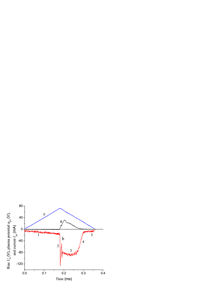
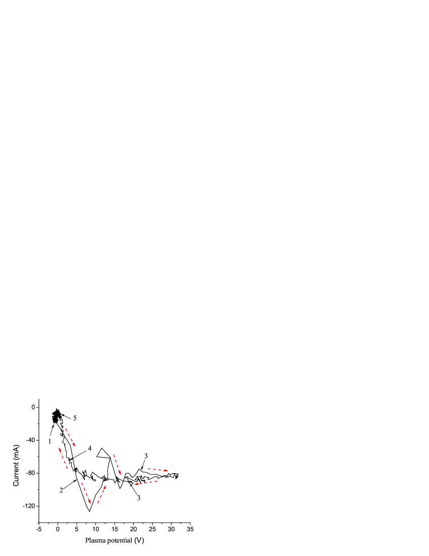
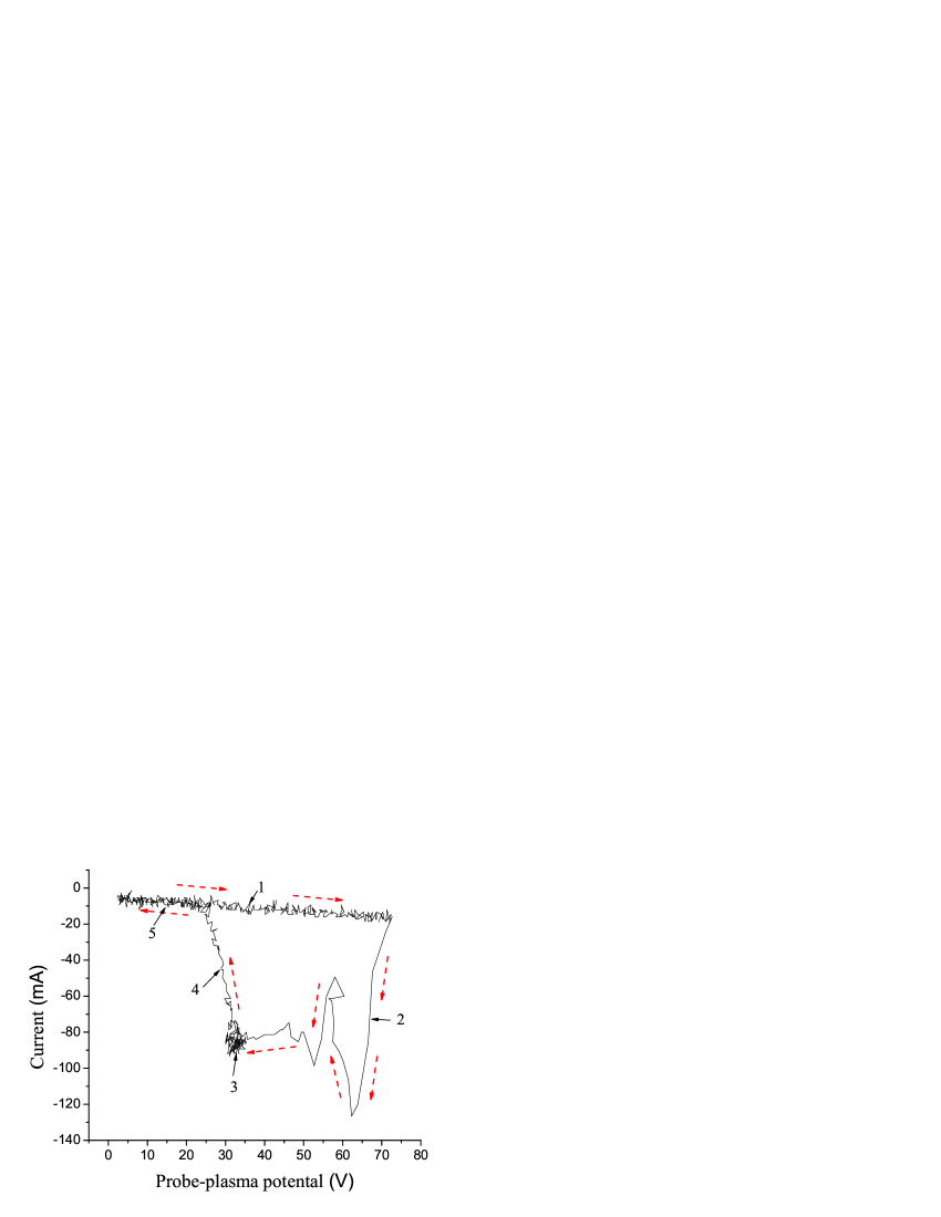
To study the C-V characteristics of such a thin probe we applied a periodic saw-tooth voltage instead of the dc (see Fig. 8). The saw-tooth duration was chosen as . On the one hand this is much longer compared to the switching time, on the other hand this is much shorter compared to the plasma pulse. The latter means that during the plasma may be recognized as stationary. As it is clearly seen in Fig. 8b, the current jump starts at a substantially higher bias compared to the bias when the current falls down. It indicates the existence of hysteresis in the probe C-V characteristics (see Fig. 8c). A very similar hysteresis loop could be seen in a wide range of plasma densities during the plasma pulse. When the pressure was a bit reduced in order to bring this bias amplitude below , no hysteresis was seen and the probe characteristics appeared as an almost straight line (see Fig. 8d), which is in a good agreement with the known theories for small probes r4 ; Mott .
To complete this study we checked the qualitative influence of the ionization level on the probe characteristics. Namely we placed in the vacuum chamber the powerful pulsed single-core FIC plasma source r3 (see Fig. 1b). It could work in the same pressure range and in our experiments we achieved ionization level %. The plasma density grew up to during a pulse. To prevent the probe damage, we biased the probe with a single variable positive voltage pulse with pulse duration of . Typical waveforms of the probe current and plasma potential are shown in Fig. 9. In the investigated range of the electron probe current could reach a few Amperes but the probe characteristics were smooth with no hysteresis, no instability of the probe current was seen and the potential fall between the plasma and wall was always low.

IV Theoretical model and analysis of the experimental data
The experimental data show that the peculiarities of the probe C-V characteristics (instability, hysteresis) are the same either in three or four electrodes schemes. It means that the discharge circuit can be eliminated from the consideration.
A positively biased probe collects electron current from the surrounding plasma. The equivalent ion current is collected by a reference electrode (the chamber wall in the experiments). The current loops through an external circuit which maintains the voltage between the electrodes. The probe and the reference electrode (thereafter cathode) currents depend on the voltage between them and the plasma: and , where , , and are the probe, plasma, and cathode potentials, respectively (thereafter . Thus, taking into account that , the plasma potential is determined by the condition:
| (2) |
In other words, the plasma potential and, consequently, the probe current are determined by both the probe and cathode C-V characteristics.
It is clear now that the dependence , which we measure in our experiments, is close to the probe characteristics when the plasma potential is small, . This is possible when the ion-collecting area (cathode area) is large enough compared with the probe area and Eq. (1) is satisfied.
When the bias voltage is large, , the effective collecting area around the small probe can exceed the probe geometric area and the condition in Eq. (1) should be written as follows:
| (3) |
When the voltage exceeds the ionization potential of the neutral gas, the ionization in the space-charge sheath around the probe can change drastically the collected current even if the electron impact ionization mean free path is large compared with the sheath thickness (see, e.g., Refs. 11-13). The probe C-V characteristics becomes three-valued with unstable middle branch and demonstrates hysteresis under a gradual increase and a subsequent decrease of the probe potential Ionita . The collected current on the stable upper and lower branches of the hysteresis loop can differ by more than an order of magnitude Klinger ; Strat .
When the probe and the cathode C-V characteristics are known, the plasma potential that satisfies Eq. (2) can be found graphically as it is depicted in Fig. 10.
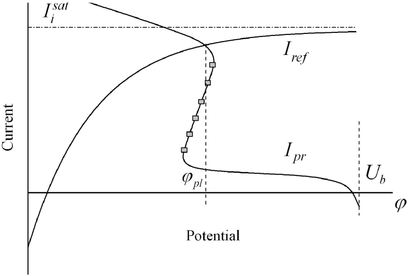
The cathode C-V characteristics is shown as a function of the potential , , whereas the probe characteristics is shown as a function of , . The intersection of these two curves defines the plasma potential and the circuit current . Under the increase/decrease of the bias voltage , the probe C-V characteristics curve is shifted right/left along the horizontal axis as a whole.
It is important to bear in mind that the probe characteristics shape depends on the probe dimension and form. Further we will consider small probes whose radii are comparable with the plasma Debye length. Such probes are characterized by the absence of a saturation current Mott . The characteristic values of the current which are inherent in the dependence (characteristic scale along the vertical axis in Fig. 10) increase/decrease monotonically with the increase/decrease of the probe radius.
Now, using this graphical representation, one can explain the experimental results described above. It is convenient to group the results in accordance with the probe radius: large, intermediate, and small probes.
Large probe. — When the probe radius is so large that the collected current exceeds the cathode saturation current even on the lower branch of the probe C-V characteristics, the intersection has the form depicted in Fig. 11. Independently of the bias voltage, the cathode characteristics intercepts only the lower stable branch of the probe characteristics.
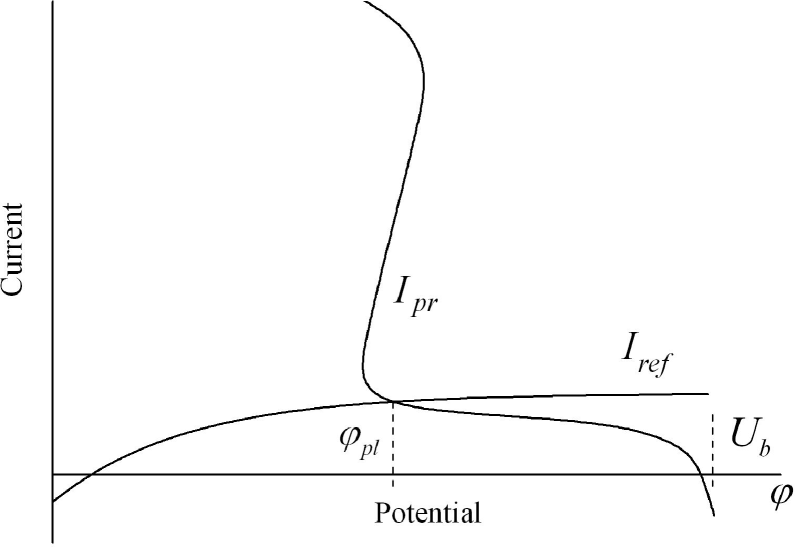
The experiments with the 5mm radius probe are related to this case (see Fig. 3).
Intermediate probe. — Under the probe radius decrease its C-V characteristics “shrinks” along the vertical axis. The possible types of the intersections between the probe and cathode characteristics are shown in Fig. 12.
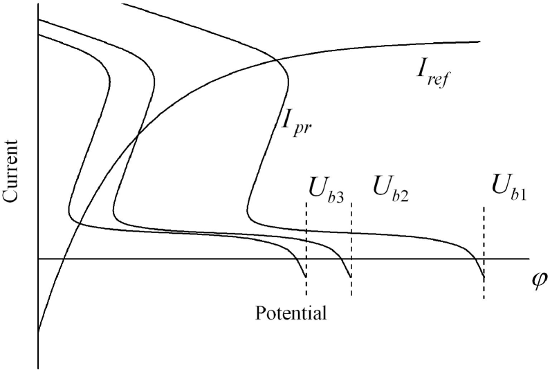
The distinctive property of the intermediate probe is the following: there is a range of bias voltage values when the cathode characteristics intercepts only the unstable branch of the probe characteristics (curve , bias voltage in Fig. 12). It means that there are no stable solutions of Eq. (2) and self-oscillations of the current in the circuit appear when the bias voltage lies in the above-mentioned range. Note that jumps from the lower to the upper branch and backwards occur in different points of the probe C-V characteristics. Therefore, the dependence should demonstrate the hysteresis-like behavior.
The experiments with 0.6-1.2 mm radius probes demonstrate these peculiarities of the intermediate probe characteristics (see Fig. 4).
Small probe. — If the probe radius is so small that the collecting current is small compared with the ion saturation current for all voltages in the range of interest, the intersection between the C-V curves in Fig. 10 is located near the cathode floating potential (potential that corresponds to zero current). The intersection types for various bias voltages are shown in Fig. 13.
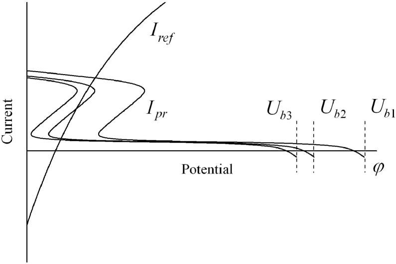
Depending on the bias voltage, the cathode C-V characteristics intercepts either the lower branch of the probe characteristics (curve , bias voltage in Fig. 13), or three branches (curve , bias voltage ), or the upper branch (curve , bias voltage ). It is important to note that independently of the bias voltage the cathode characteristics always intercepts the stable branches (upper and lower branches, the intermediate branch is always unstable) of the probe characteristics. In this case there are stable solutions (either one or two) of Eq. (2) for all values of the bias potential. The C-V characteristics demonstrates hysteresis under a gradual increase and a subsequent decrease of the potential .
This qualitative analysis explains the experimental results related to the small (less than 0.1 mm diameter) probe presented in Figs. 14, 15, and 16.
The current circuit contains two elements: the plasma-probe sheath and the plasma-cathode sheath. The first one is characterized by a multi-valued C-V characteristics , whereas the C-V characteristics of the second one is a single-valued function . It means that under a gradual increase and a subsequent decrease of the potential , the dependence should be a single-valued function, despite the fact that the dependence demonstrates hysteresis. This conclusion is confirmed by the experimental data shown in Figs. 15 and 16. Relatively small deviations from the single-valued dependence (small hysteresis loops) reflect transient processes of the plasma-cathode sheath reconstruction caused by fast variations of the plasma potential under the “jumps” between the lower and upper branches of the probe C-V characteristics r2 ; Bliokh .
The key element in the qualitative analysis above is the additional ionization inside the current-collecting sheath around the probe. Additional ions can essentially increase the sheath radius if the number of ions in the sheath is comparable with the number of electrons . Assuming that the ionization take place in all the sheath volume, it is possible to make the following rough estimate of . Any electron entering the sheath produces ions, where is the gas density, is the ionization cross section, and is the sheath radius. Thus, , where is the characteristic residence time of the particle in the sheath, and is the characteristic velocity of the particle. Because electrons and ions are accelerated by the same potential drop, , where is the ion mass. Thus,
| (4) |
Under typical experimental conditions (, , ) the number of ions in the sheath is comparable with the number of electrons , , when the sheath radius is of the order of 1cm. This estimation is in a good agreement with the experimental data. Indeed, approximately the same radius cm of the probe collecting area may be obtained directly from the amplitude of the probe current spikes (Fig. 4 – Fig. 8). This is correct in a wide range of plasma densities [emission currents mA]. Experiments with various spirals placed around the probe showed also that the spiral did not disturb the current-collecting area when the spiral radius exceeds 1 cm.
The above estimation of the number of ions in the sheath supposes implicitly that the neutral gas density is large enough so as to provide creation of this amount of ions. However, it does not always happen. In the vicinity of a small probe the electron density exceeds many times the plasma density due to the geometric focusing of the collected particles. The ionization rate in this region can be so large that the ionization degree would reach 100% during the ion residence time or even faster. In this case the number of ions is always smaller than the number of electrons in the sheath and the probe C-V characteristics is single-valued.
Let us estimate the sheath region where the ionization degree is small, and the condition
| (5) |
is satisfied. The ions production rate in a layer of radius is described by the following equation:
| (6) |
where and are the collected electrons density and velocity, respectively. During the ion residence time the ionization degree reaches the value:
| (7) |
Here the particles flux conservation law is used.
When the condition (5) is satisfied, the ionization degree is small, and in a sheath region of radius
| (8) |
It follows from Eq. (8) that the region, where the neutral gas density cannot provide production of the required amount of ions, occupies a considerable part of the sheath volume when the plasma density is large enough, all other factors being the same.
In the set of experiments where plasma is created by discharge with a hot cathode the ratio is small and the probe C-V characteristics is multi-valued. In contrast, in the experiments with the FIC plasma source this ratio is large, , and hence the probe current is stable and self-oscillations are not observed despite that the potential fall between the probe and the plasma could significantly exceed the ionization potential.
V Summary
The characteristics of small positively biased electrodes (probes) immersed into a plasma have been studied. These probes were much smaller than the reference electrode size divided by the square root of the ion/electron mass ratio. The electron current branch of the C-V characteristics of such probes is widely used to measure the local plasma parameters. Additional ionization of neutral gas by electrons accelerated in the space-charge sheath around the probe could significantly expand the sheath thickness. However, we were focused on the case, when the sheath thickness still remains small compared to the whole plasma and reference electrode sizes. It should be emphasized that in our experiments this additional ionization inside the sheath does not change the plasma parameters in the whole volume. When the probe dimension is large compared to the sheath thickness, the sheath expansion does not affect the current collected by the probe from the plasma. On the other hand, near a very small probe the sheath expansion induced by the ionization leads to considerable increase of the collected current.
The probe current loop is closed through the ion-collecting electrode (cathode) having its own C-V characteristics. The potential fall between the cathode and the plasma should rise to support the increasing current. The plasma potential growth changes the potential drop between the probe and the plasma, and the probe current should be changed in accordance with the probe C-V characteristics. Thus, the current is determined by the relation between the probe and the reference electrode C-V characteristics.
It has been shown both experimentally and theoretically that these small probes can be separated into three groups according to the probe dimensions. Every group is characterized by its particular dependence of the collected current on the bias voltage. The current collected by the “large” probes increases monotonically and continuously with the voltage growth. The probes with an “intermediate” size are characterized by excitation of strong periodic spike-like oscillations under a constant bias voltage. The current collected by the “small” probes is stable, but changes stepwise under certain bias voltage values and demonstrates hysteresis under a gradual increase and a subsequent decrease of the bias voltage. Both oscillations and current steps are caused by additional ionization in the probe vicinity. Note, that the same probe can be treated as either large, intermediate, or small depending on the value of the reference electrode area. Ignoring the possibility of probe-current instability, neither the plasma density nor the electron temperature could be measured correctly by this probe even if the oscillations are filtered out, averaged etc. In the case of stepwise jumps of the probe current the upper current level does not reflect directly the plasma parameters in the place where the probe is located.
In conclusion, we have demonstrated that under certain conditions, phenomena related with Langmuir probes cannot be correctly interpreted once considered separately from the reference electrode characteristics.
References
- (1) R.L. Stenzel, Phys. Fluids B 1, 2273 (1989).
- (2) T.Klinger, F. Greiner, A. Rohde, and A. Piel, Phys. Plasmas 2, 1822 (1995).
- (3) R.L. Stenzel, C. Ionita, and R. Schrittweiser, Plasma Sources Sci. Technol. 17, 035006 (2008).
- (4) V.E. Golant, Sverkhvysokochastotnye metody issledovaniya plasmy (Nauka, Moscow, 1968) chap. 8, p. 217 (in Russian).
- (5) Y.P. Bliokh, Yu.L. Brodsky, Kh.B. Chashka, J. Felsteiner, and Ya.Z. Slutsker, J. Appl. Phys. 103, 053303 (2008).
- (6) Y.P. Bliokh, J. Felsteiner, Ya.Z. Slutsker, and P.M. Vaisberg, Appl. Phys. Lett. 85, 1484 (2004); Y.P. Bliokh, Yu.L. Brodsky, Kh.B. Chashka, J. Felsteiner, and Ya.Z. Slutsker, J. Appl. Phys. 107, 015009 (2010).
- (7) F.F. Chen, in Plasma Diagnostics Techniques, Eds. R.H. Huddlestone and S.L. Leonard (Academic, NY, 1965), chap. 4.
- (8) H.M. Mott-Smith and I. Langmuir, Phys. Rev. 28, 727 (1926); I.B. Bernstein and I.N. Rabinowitz, Phys. Fluids 2, 112 (1959); F. Chen, J. Nucl. Energy, Part C 7, 47 (1965); J.E. Allen, Phys. Scr. 45, 497 (1992).
- (9) S. Chiriac, D.G. Dimitriu, and M. Saduloviciu, Phys. Plasmas 14, 072309 (2007).
- (10) R.L. Stenzel, Phys. Rev. Lett. 60, 704 (1988).
- (11) D.L. Cook and I. Katz, J. Spacecraft 25, 132 (1987).
- (12) C. Ionita, D.-G. Dimitriu, and R.W. Schrittweiser, Int. J. Mass Spectrom. 233, 343 (2004).
- (13) L. Conde, C. Ferro Fontan, and J. Lambas, Phys. Plasmas 13, 113504 (2006).
- (14) M. Strat, G. Strat, and S. Gurliu, Phys. Plasmas 10, 3592 (2003).
- (15) Y.P. Bliokh, J. Felsteiner, Ya.Z. Slutsker, and P.M. Vaisberg, Phys. Plasmas 9, 3311 (2002).