Effect of carrier doping on the formation and collapse of magnetic polarons in lightly hole-doped La1-xSrxCoO3
Abstract
We investigate the doping dependence of the nanoscale electronic and magnetic inhomogeneities in the hole-doping range of cobalt based perovskites, La1-xSrxCoO3. Using single crystal inelastic neutron scattering and magnetization measurements we show that the lightly doped system exhibits magneto-electronic phase separation in form of spin-state polarons. Higher hole doping leads to a decay of spin-state polarons in favor of larger-scale magnetic clusters, due to competing ferromagnetic correlations of Co3+ ions which are formed by neighboring polarons. The present data give evidence for two regimes of magneto-electronic phase separation in this system: (i) , dominated by ferromagnetic intrapolaron interactions, and (ii) , dominated by Co3+-Co3+ intracluster interactions. Our conclusions are in good agreement with a recently proposed model of the phase separation in cobalt perovskites [He et al., Europhys. Lett. 87, 27006 (2009)].
pacs:
75.47.Lx, 36.40.Cg, 78.70.Nx, 75.30.CrI INTRODUCTION
It is generally accepted that the development of a magnetoelectronic phase separation (MEPS) in hole-doped perovskite cobaltites La1-xSrxCoO3 plays a crucial role for their magnetic and transport properties. As found by various experimental techniques, such as nuclear magnetic resonance,Kuhns et al. (2003); Hoch et al. (2004); Podlesnyak et al. (2008) small-angle scattering,Wu et al. (2005) diffraction,Caciuffo et al. (1999) inelastic neutron scattering (INS),Phelan et al. (2006a, b); Podlesnyak et al. (2008) transmission electron microscopy,Caciuffo et al. (1999) extended x-ray absorption fine structure (EXAFS) measurements,Sundaram et al. (2009) magnetometryGiblin et al. (2006, 2009) and heat capacity measurements,He et al. (2009a, b) the phase separation leads to the formation of ferromagnetic (FM) clusters in a nonferromagnetic matrix upon carrier injections. Recent theoretical efforts,Dagotto (2003); Kugel et al. (2008); Sboychakov et al. (2009); Suzuki et al. (2009) mainly based on the early ”ferrons” ideas of Nagaev,Nagaev (1967); Nagaev and Podel shchikov (1996); Nagaev (2002) contributed to considerable progress in the understanding of the origin of electronic phase separation in a wide doping range. The consensus is that the low temperature phase diagram starts from a nonmagnetic state at , and upon doping includes two large regions of spin-cluster glass (SG) and ferromagnetic (FM) states with a metal-insulator transition (MIT) at .Wu et al. (2005); Phelan et al. (2006b); Itoh et al. (1994); Señarís-Rodríguez and Goodenough (1995); He et al. (2007) The nonmagnetic ground state of the parent compound, LaCoO3, corresponds to a low-spin (LS) state of Co3+ ions (, ).eae (a) Due to subtle balance between the intra-atomic (Hund’s) exchange interaction and the crystal-field splitting , the first excited state is located at about 10 meV (0.5-0.7 % of )eae (b) above the LS state.Podlesnyak et al. (2006); Haverkort et al. (2006); He et al. (2009c) The closeness in energy of these states makes LaCoO3 a well-known spin-state transition model system. The SG state is characterized by a hole-poor nonferromagnetic matrix with embedded hole-rich FM droplets.Wu et al. (2005) The nonferromagnetic spin correlations in the matrix,Phelan et al. (2009) FM intracluster correlationsCaciuffo et al. (1999) and magnetic interactions between the matrix and FM clustersGiblin et al. (2006); Phelan et al. (2006a) give rise to the inhomogeneous magnetic nature of La1-xSrxCoO3.
In a recent comprehensive study He et al. suggested that MEPS occurs only in a well-defined doping range, .He et al. (2009a, b) They showed that the phase separation is controlled solely by the site occupation randomness introduced by the doping, and is not electronically driven.He et al. (2009b) At increasing the clusters eventually reach the percolation limit leading first to short-range magnetic order at , and then long-range FM order at .Wu et al. (2005); Phelan et al. (2006b) At the system becomes a ferromagnetic metal, although FM and non-FM clusters coexist well above the MIT in a composition range often characterized as cluster-glass (CG) region.Itoh et al. (1994); Wu and Leighton (2003); Kuhns et al. (2003) Results obtained by polarized neutron inelastic scattering in ferromagnetic La0.82Sr0.18CoO3 suggest that low-energy spin excitations can be described in terms of a simple localized Heisenberg ferromagnet.Ewings et al. (2010)
Much less is known about the development of the MEPS around the low limit of . Different experimental techniques proved that the system is phase separated below this limit as well.Podlesnyak et al. (2008); Yamaguchi et al. (1996); Giblin et al. (2006); Smith et al. (2008) Recently, we elucidated the mechanism of how already the light hole doping dramatically affects magnetic properties of LaCoO3,Podlesnyak et al. (2008) an effect first discovered by Yamaguchi et al. Yamaguchi et al. (1996) Our analysis revealed that the charges introduced by substitution of Sr2+ for La3+ do not remain localized at the Co4+ sites. Instead, each hole is extended over the neighboring Co3+ ions, transforming them to a higher spin state and thereby forming a magnetic spin-state polaron. Important questions remain: How do the polarons behave with increasing Sr content across the low limit proposed for the ”true” magnetoelectronic phase separation border? What is the characteristic distinction between these, both magnetically inhomogeneous, states?
In this work, combining single crystal INS with magnetization data of La1-xSrxCoO3, we present a detailed study of the doping dependence of the magneto-electronic phase separation through the critical limit . We give unambiguous evidence that at low doping, , the nanoscale MEPS is stabilized in the form of heptamer FM spin-state polarons in a non-FM matrix. We also show that further hole doping above the critical limit leads to a decay of spin-state polarons mainly due to FM exchange of neighboring Co3+ ions of different polarons at the expense of AFM interpolaron interactions. In turn, this results in the appearance of hole-rich FM clusters in significant size and density, stabilizing the CG region.
II EXPERIMENTAL
II.1 Sample preparation
Starting powders for single crystal growth of La1-xSrxCoO3, were synthesized by a solid state reaction using La2O3, SrCO3 and Co3O4 of a minimum purity of 99.99%. Stoichiometric amounts of the oxides and carbonates were ground thoroughly and fired at temperatures from 850 to 1200∘C several times. The complementary powders of LaCoO3, Ca, Y, were prepared as well using appropriate carbonate and oxide (CaCO3, Y2O3). About g of each polycrystalline sample was prepared, and therefore the absolute mass of the dopant could be weighed with sufficient accuracy. The phase purity of the synthesized compounds was verified by means of powder x-ray diffraction. Single crystals were grown using an Optical Floating Zone Furnace.
Particular attention was paid to the oxygen stoichiometry of the samples and the homogeneity of the Sr doping along the length of the as-grown crystals. The oxygen content of polycrystalline and single crystal samples was determined by thermogravimetric hydrogen reduction.Conder et al. (2005) The oxygen nonstoichiometry, which can produce effects similar to Sr doping, was found to be less than 0.01. The small concentration of the doping element made it difficult to control the distribution of strontium along the grown crystals with laboratory techniques such as x-ray diffraction or energy dispersive x-ray analysis alone. It is known that the low temperature magnetic susceptibility for lightly doped samples is remarkably increased with such light doping.Yamaguchi et al. (1996) Therefore, we compared the temperature dependent magnetization of small crystal pieces taken from different places of the as-grown crystals. The results of the magnetization measurements obtained for all the crystal pieces and also for starting powder were identical (within each strontium concentration) and consistent with previously published data, where available.Yamaguchi et al. (1996) This proved that (i) the strontium distribution was homogeneous throughout the sample volume and (ii) the actual dopant concentration was close to the nominal value.
II.2 Instrumentation
INS experiments on single crystal samples of La1-xSrxCoO3 were performed at the Cold Neutron Chopper Spectrometer (CNCS) at the Spallation Neutron Source in Oak Ridge,CNC at the backscattering spectrometer IRIS at the ISIS neutron scattering facility, and at the time-of-flight spectrometer FOCUS at the Swiss spallation neutron source SINQ at PSI.Janssen et al. (1997) For the CNCS measurements the single crystal () was mounted in the (H,H,L) scattering plane (throughout the paper we use the pseudocubic notation with the scattering wave vector , given in reciprocal lattice units (r.l.u.)). The measurements were done at temperatures from 1.5 to 40 K with an incident neutron energy meV. At this energy the instrumental elastic energy resolution, full width at half maximum, was 70 eV. The data at FOCUS () were collected in the (H,K,0) scattering plane using an incident neutron energy meV, giving an elastic resolution of 150 eV. The IRIS experiment (samples with Sr concentration and in the (H,H,L) scattering plane) used the pyrolitic graphite (004) reflection to select a fixed final energy meV resulting in a resolution of eV at the elastic position. The data were corrected for detector efficiency using a vanadium standard. The program MSLICE ported in the DAVE software package was used for data visualization and analysis.Msl Magnetization measurements were performed using a SQUID MPMS magnetometer.
III RESULTS AND DISCUSSION
III.1 Inelastic Neutron Scattering
III.1.1 La1-xSrxCoO3, ; the case of weakly interacting spin-state polarons
No magnetic excitations have been found for temperatures K in the parent compound LaCoO3.Podlesnyak et al. (2006) An inelastic peak at meV was found at intermediate temperatures starting from K. This excitation is due to a thermally excited HS magnetic state of Co3+ ions in the non-disturbed LaCoO3 matrix, as was discussed in our previous work.Podlesnyak et al. (2006) Earlier INS experiments on lightly hole-doped polycrystalline La1-xSrxCoO3 () provided evidence for the existence of octahedrally shaped polarons which consist of a central Co4+ ion in LS state configuration, , surrounded by six Co3+ ions along the three cube axes in intermediate spin state with spin .Podlesnyak et al. (2008) This conclusion was largely based on the dependence of the magnetic peak intensity observed for a polycrystalline sample of La0.998Sr0.002CoO3 at energy transfer meV and also on the Zeeman splitting of this peak in magnetic field, see Fig. 1 in Ref. Podlesnyak et al., 2008. This peak in the INS spectrum corresponds to the transition between the ground state levels of the Co heptamer split by a weak trigonal crystal field. The details of the nature of this magnetic excitation will be discussed in the Appendix. The neutron cross section for polycrystalline samples can be written down as a superposition of damped sine functions:
| (1) |
where is the magnetic form factor, the modulus of the scattering vector, and denotes the position vector of the th Co ion. Although the data displayed in Ref. Podlesnyak et al., 2008 are best described by a Co heptamer (n=7), other types of magnetic clusters cannot be excluded unambiguously. In particular, the dependencies of the magnetic intensities for the heptamer and octamer (n=8) clusters are rather similar. The values of the saturated magnetic moments, for n=7 and for n=8, are also too close to be distinguished by magnetization measurements. However, a clear-cut discrimination is possible by studying single crystals. In this case the neutron cross section has the form
| (2) |
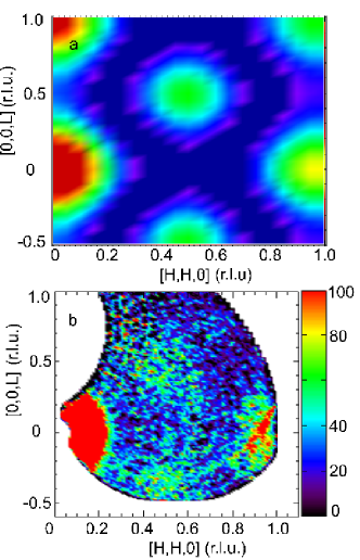
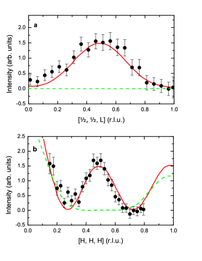
Eq. 2 gives rise to well defined intensity minima and maxima for different scattering vectors (see Fig. 1 a), which are characteristic of the geometry of the magnetic cluster, contrary to Eq. 1 where this information is smeared out due to the powder average in space. For instance, Eq. 2 predicts intensity at for a heptamer, in strong contrast to the octamer where zero intensity is expected at the same position. In order to verify the model, we mapped out the distribution of the intensity of the magnetic excitation at meV within the (H,H,L) plane at K. We found that the measured integrated intensity of the magnetic inelastic peak shows clear oscillatory behavior with a maximum intensity at (see Fig. 1 b) in full agreement with the calculated intensity for Co heptamers, Fig. 1 a. This is also exemplified in Figs. 2 a,b for measurements with the scattering vector along principal symmetry directions. In all cases the fit to the heptamer configuration is rather good, whereas the octamer magnetic cluster model cannot satisfactorily fit the data along the = [H,H,H] and [,,L] directions.
Similar results were also obtained for other single crystal samples in this study with , and . In all cases at low temperatures we observe intense resolution limited inelastic peaks at meV. An additional INS peak at meV, due to the undoped LaCoO3 matrix, appears in the measurements at elevated temperatures, K. The positions of the peaks do not depend on doping. The excitations are dispersionless, indicating that intercluster interactions are weak and can be neglected. Therefore, we conclude that in the light hole doping regime, , a magnetoelectronic phase separation in the form of weakly interacting 7-site spin-state polarons in the nonmagnetic matrix is realized.
III.1.2 La1-xSrxCoO3, ; decay of the spin-state polarons
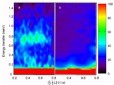
The situation becomes more complicated if interpolaron interactions or/and interactions between individual magnetic cobalt ions exist (either IS Co3+ or LS Co4+) which belong to neighboring polarons. In order to explore the behavior of the magnetic excitations at doping level above suggested as a lower limit of MEPS,He et al. (2009a) we measured INS spectra of two samples and . Although the quantitative comparison of INS peak intensities from the data obtained at different spectrometers is difficult, the qualitative tendency is obvious. We found that the peak at meV, which was the main magnetic feature of the system with , is considerably suppressed at and totally disappears at . Our INS measurements provided no evidence for any dispersion of the 0.75 meV excitation, thus ruling out intercluster interactions as the origin of cluster-glass state. Fig. 3 shows the observed inelastic intensity around obtained from La1-xSrxCoO3, and 0.1. The comparison suggests that the isolated spin-state polarons decay rapidly with hole-doping and can be hardly detected at .
Note, that the high temperature INS peak at meV remains constant at increasing and then vanishes completely for . Here we would like to refine the corresponding part of La1-xSrxCoO3 phase diagram. The recently proposed magnetic phase diagramWu and Leighton (2003); He et al. (2007) includes one more region in addition to the SG and CG-FM states.Itoh et al. (1994) This is the spin-state transition (SST) region at the very left side, , of the diagram. is proposed to rapidly fall down from K to . This is in contrast to the phase diagram proposed in Ref. Señarís-Rodríguez and Goodenough, 1995, where K remains roughly constant for . The of the thermally induced spin-state transition (or rather crossover) is determined by energy gap from the LS ground state to a first excited magnetic state of Co3+ ions in a nondisturbed LaCoO3 matrix. The energy gap in undoped parent compound LaCoO3 was determined by means of inelastic neutron scattering and turns out to be meV.Podlesnyak et al. (2006) It follows from our current INS measurements that this LS HS energy gap and hence does not depend on Sr-doping. This is indeed quite natural: it is not plausible that the doping on the level of several spins per thousand nonmagnetic ions would collapse the magnetic state of an entire system. Therefore, we conclude that K in the main part of this region, and rather rapidly vanishes at , when polarons start to strongly overlap.
The data obtained from La1-xSrxCoO3, also reveal the clear presence of elastic diffuse scattering around the ferromagnetic (0,0,1) wave vector, which was not observed at . To confirm the magnetic origin of the diffuse intensities we mapped out the elastic scattering at two temperatures 1.5 and 100 K. Fig. 4 shows a difference in the intensities obtained at temperatures 1.5 and 100 K, . The elastic scattering, indicative of static FM correlations, has a highly anisotropic shape. The diffuse intensity extends along the (1,1,1) direction all the way to (,,,). Note, that similar elastic diffuse scattering was reported by Phelan et al. Phelan et al. (2006a, 2009) Their spin-polarized measurements also proved that the observed intensities are dominantly magnetic in nature.Phelan et al. (2009) Moreover, they reveal static incommensurate magnetic correlations not observed in our measurements. These results are indicative of coexisting and competing FM and AFM correlations. For the hole-doping concentration the FM interactions become static, suggesting that relatively large FM clusters are formed at the expense of spin-state polarons.

III.2 Magnetization
Substitution of La3+ with Sr2+ provides hole doping and creates a mixed Co3+-Co4+ system. However, the Sr2+ ion has a bigger ionic radius (1.18 Å and 1.032 Å, for Sr2+ and La3+, respectively), that can also locally distort the crystal structure. Therefore, the Sr2+ substitution leads not only to the hole injection, but may also change in doped clusters. In order to understand the role of local structure distortions in the observed magnetic effects we measured the dc magnetic susceptibility of LaCoO3 doped with Sr2+, Ca2+ and Y3+.
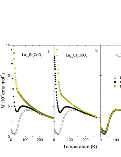
Yttrium is an isovalent ion to lanthanum, however, with a much smaller ionic radius (0.90 Å). One can expect that distortions due to Y3+ doping would be even larger compared to strontium substitution. On the other hand, Ca2+ has an ionic radius of 1.00 Å, close to La3+. The magnetic susceptibility curves show a pronounced doping effect in case of Sr and Ca doping (Fig. 5 a,b). The susceptibility exhibits a strong increase at low temperatures compare to parent compound LaCoO3. At increasing temperature the susceptibility goes through the broad maximum at K indicating thermal activation of Co3+ HS state ions. On the other hand, in case of Y3+ doping very little changes of the magnetic susceptibility were observed compared to the undoped LaCoO3 (Fig. 5 c). This is unambiguous evidence that the substitution of La3+ for Sr2+ provides mainly holes to the system without creation of a sizable crystal field distortion in the doped clusters. The hole doping is the main origin for the observed low temperature magnetic anomalies. This is unambiguous evidence that the substitution of La3+ by Sr2+ acts mainly by providing holes to the system, and not by a crystal field distortion in the doped clusters. Thus the hole doping is the main origin for the observed low temperature magnetic anomalies.
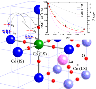
The low temperature field dependence of the magnetization per doped hole, (or, in other words, per Co4+) for different doping concentrations is shown in Fig. 6. It is worth to mention that Co4+ is expected to be in LS state (), thus the expected magnetic moment is . In order to estimate an effective magnetic moment we fitted measured magnetization with a combination of the conventional Brillouin function B and a field-linear term, , .Yamaguchi et al. (1996) The resulting values are shown as full dots in the inset of Fig. 7. For the lowest doping the magnetization curves correspond to the saturation moment /hole, which is much higher than one can expect from single Co4+ or Co3+ in any spin state. This result combined with the INS data for the lightly doped cobaltites fully supports our spin-state polaron model. Each injected hole triggers off neighboring Co3+ to the IS magnetic state creating a magnetic cluster with . A reasonable mechanism for such a resonant state with a hole ”dressed” by the magnetic cloud was proposed by Louca and Sarrao.Louca and Sarrao (2003) Fig. 7 represents a schematic view of such a spin-state polaron. Neighboring LS Co4+ and IS Co3+ ions share an electron by swapping configuration that would be energetically favorable for hopping. The electrons, in turn, couple ferromagnetically via double exchange interaction thus forming a giant magnetic moment.
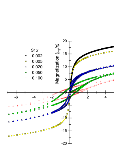
Surprisingly, the magnetization curves tend to saturate at lower values upon hole doping indicating a rapid reduction of the magnetic moment per hole. For low (well below the percolation threshold) it is natural to expect that the phase-separated system would consist of almost noninteracting spin-state polarons with giant magnetic moment, separated by the nonmagnetic LaCoO3 matrix. The value of the moment should remain roughly constant since the number of polarons is proportional to till such polarons start to overlap. However, as one can see in Fig. 6 and in inset of Fig. 7, rapidly drops down to /hole, the values which are characteristic of the magnetic moment of a single cobalt ion. This result provides further evidence that the spin-state polarons collapse as is increased.
The paramagnetic Curie temperature is another value to elucidate interspin interactions. The value of is an arithmetic average of the interspin coupling constants ,
| (3) |
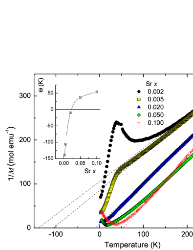
where the sum is over all interacting spins (see, for instance, Ref. Czachor, 1995). That is, in case of several subsystems with competing magnetic interactions in a phase separated compound the value provides an indicator of their relative strength. The temperature dependence of the inverse magnetic susceptibility was measured in field T on heating from low temperatures after zero field cooling (Fig. 8). Although the spin-state crossover makes a fit to the Curie law difficult at low temperatures, we were able to estimate the paramagnetic Curie temperature by fitting the range K. As shown in the inset of the Fig. 8, quickly increases from negative to positive values with increasing , crossing zero at about . This suggests that the strength of competing FM-AFM contributions to strongly depends on doping level and FM-AFM correlations become comparable around the MEPS low limit, .
As we already mentioned in the introduction, three different types of magnetic interactions compete in lightly hole-doped La1-xSrxCoO3: 1) intrapolaron interactions between IS Co3+ and HS Co4+; 2) interpolaron interactions as well as polaron - undoped matrix interactions at elevated temperatures; and 3) interactions between individual Co spins from different spin-state polarons (for low ) or magnetic clusters (for higher ). Intrapolaron interactions are ferromagnetic via double exchange interaction and cause of the giant moment. The negative values of in the lightly doped system as well as neutron scattering dataPhelan et al. (2006b, 2009) indicate that thermally-excited magnetic (HS/IS) states interactions are mainly AFM. The hysteresis loops which are observed in La1-xSrxCoO3 for emphasize that the FM interactions become prominent starting from these elevated . Note, that coexisting and competing FM and AFM correlations in hole-doped cobaltites were proved by various different techniques, such as neutron scattering,Phelan et al. (2006b, 2009) specific heat,He et al. (2009a, b) magnetic susceptibility,Androulakis et al. (2001) NMR,Kuhns et al. (2003) and SR.Giblin et al. (2006)
It is apparent that the interactions between individual cobalt ions from neighboring polarons is negligible in the system with low . They become more and more important with increased doping. As a consequence of the statistical clustering of Co4+, the number of isolated polarons rapidly decreases in favor of interacting ones. To estimate how such Co-Co interactions are related to the magnetic properties of La1-xSrxCoO3, we apply a simple geometrical consideration. Since the spin-state polaron has octahedral shape (see Fig. 7), it can be considered as isolated when for the given central Co4+ ion all neighbors from the first to the fourth shell are in the Co3+ state. Otherwise, two polarons share a common IS Co3+. This gives us six nearest neighbors along the edge, plus twelve ions along the face diagonal, plus eight along the body diagonal and six more along the edge at two unit cells distance - altogether 32 ”blocked” sites. For any given Co4+ ion the probability to find all neighbors in Co3+ is (Co4+-Co. As one can see from the inset in Fig. 7 the value of the magnetic moment as a function of is indeed best scaled with the curve which takes into account all neighbors from the first to the fourth shell. This suggests that the FM interactions between neighboring IS Co3+-Co3+ out of different polarons overcome the AFM correlations of polarons themselves when the interpolaron distance is reduced to the order of two unit cells. Since the Co3+ ions that are situated between two Co4+ polaron centers experience both FM intra- and AFM interpolaron interactions they turn out to be frustrated. The decay of polarons on further increasing gives rise to the larger-scale clusters with competitive FM-AFM interactions (i.e. cluster-glass state), which is confirmed by the decrease of the magnetic moment with simultaneous increasing of hysteresis loop. Note, that the clear deviation of the from the calculated curve above the critical doping can be also explained by the growing magnetic contribution from the larger-scale clusters.
Our findings are in good agreement with conclusions of He et al. He et al. (2009b, a). They argued that the phase separation i) is restricted to a well-defined doping range, , and ii) is driven solely by inevitable local compositional randomness at nanoscopic length scale. Combining these ideas with the present neutron scattering and magnetization data, we can suggest that the hole concentration is a crossover from polaron type of magneto-electronic inhomogeneity to a state with ferromagnetic spin clusters which are formed at the expense of spin-state polarons.
IV CONCLUSIONS
We have performed a comprehensive study of inelastic neutron scattering and magnetization in La1-xSrxCoO3 single crystals, . We conclude that the magnetoelectric phase separation for the lightly hole-doped cobaltites, , has the form of the seven-site octahedral spin-state polaron and thus is an electronically driven process as opposed to the doping-driven phase separation at . We confirm that FM-AFM frustrated interactions coexist over wide composition range. The agreement between experiment and our simple statistical calculations implies that with increasing the strong ferromagnetic correlations are associated with Co-Co rather than interpolaron interactions. According to our inelastic neutron scattering measurements the low spin – high spin energy gap of Co3+ matrix, and hence , remains roughly constant with Sr-doping up to .
*
Appendix A
Considering only nearest-neighbor coupling , the Heisenberg exchange Hamiltonian is given by , where and . The total spin is . The heptamer states are therefore defined by the wave functions with and . With this choice of spin quantum numbers, the Hamiltonian is diagonal; thus, the energy eigenvalues can readily be derived, . The Co-Co coupling is ferromagnetic via the double exchange mechanism.Louca and Sarrao (2003) The ground state of the Co heptamer is therefore the state with maximum spin quantum numbers, namely with energy . The first-excited state is then with , i.e., it is separated from the ground state by the energy . The exchange coupling of Co3+ oxides is of the order of 20 meV, thus, the first-excited heptamer state lies far above the energy window covered by the present experiments. LaCoO3 crystallizes in the rhombohedral space group . Therefore, the ground state is split by the trigonal ligand field into seven doublets . Thus we identify the peak observed at 0.75 meV with the lowest transition . In fact, the observed temperature dependence of its intensity supports this interpretation.Podlesnyak et al. (2007)
Acknowledgements.
The authors thank N. Baranov for fruitful discussions. This work is partly based on experiments performed at the Swiss spallation neutron source SINQ, Paul Scherrer Institute, Switzerland and ISIS facility, UK. This research at Oak Ridge National Laboratory s Spallation Neutron Source was sponsored by the Scientific User Facilities Division, Office of Basic Energy Sciences, U. S. Department of Energy. Research at ORNL is partly sponsored by the Materials Sciences and Engineering Division, Office of Basic Energy Sciences, US Department of Energy. ORNL is managed by UT-Battelle, LLC, under contract DE-AC05-00OR22725 for the U.S. Department of Energy. The authors are grateful for the local support staff at SNS, ISIS and PSI. The work of E.P. was partly supported by the NCCR program MaNEP.References
- Kuhns et al. (2003) P. L. Kuhns, M. J. R. Hoch, W. G. Moulton, A. P. Reyes, J. Wu, and C. Leighton, Phys. Rev. Lett. 91, 127202 (2003).
- Hoch et al. (2004) M. J. R. Hoch, P. L. Kuhns, W. G. Moulton, A. P. Reyes, J. Wu, and C. Leighton, Phys. Rev. B 69, 014425 (2004).
- Podlesnyak et al. (2008) A. Podlesnyak, M. Russina, A. Furrer, A. Alfonsov, E. Vavilova, V. Kataev, B. Büchner, T. Strässle, E. Pomjakushina, K. Conder, et al., Phys. Rev. Lett. 101, 247603 (2008).
- Wu et al. (2005) J. Wu, J. W. Lynn, C. J. Glinka, J. Burley, H. Zheng, J. F. Mitchell, and C. Leighton, Phys. Rev. Lett. 94, 037201 (2005).
- Caciuffo et al. (1999) R. Caciuffo, D. Rinaldi, G. Barucca, J. Mira, J. Rivas, M. A. Señarís-Rodríguez, P. G. Radaelli, D. Fiorani, and J. B. Goodenough, Phys. Rev. B 59, 1068 (1999).
- Phelan et al. (2006a) D. Phelan, D. Louca, K. Kamazawa, S.-H. Lee, S. N. Ancona, S. Rosenkranz, Y. Motome, M. F. Hundley, J. F. Mitchell, , et al., Phys. Rev. Lett. 97, 235501 (2006a).
- Phelan et al. (2006b) D. Phelan, D. Louca, S. Rosenkranz, S.-H. Lee, Y. Qiu, P. J. Chupas, R. Osborn, H. Zheng, J. F. Mitchell, J. R. D. Copley, et al., Phys. Rev. Lett. 96, 027201 (2006b).
- Sundaram et al. (2009) N. Sundaram, Y. Jiang, I. E. Anderson, D. P. Belanger, C. H. Booth, F. Bridges, J. F. Mitchell, T. Proffen, and H. Zheng, Phys. Rev. Lett. 102, 026401 (2009).
- Giblin et al. (2006) S. R. Giblin, I. Terry, D. Prabhakaran, A. T. Boothroyd, J. Wu, and C. Leighton, Phys. Rev. B 74, 104411 (2006).
- Giblin et al. (2009) S. R. Giblin, D. Prabhakaran, A. T. Boothroyd, and C. Leighton, Phys. Rev. B 79, 174410 (2009).
- He et al. (2009a) C. He, S. Eisenberg, C. Jan, H. Zheng, J. F. Mitchell, and C. Leighton, Phys. Rev. B 80, 214411 (2009a).
- He et al. (2009b) C. He, S. El-Khatib, J. Wu, J. W. Lynn, H. Zheng, J. F. Mitchell, and C. Leighton, Europhys. Lett. 87, 27006 (2009b).
- Dagotto (2003) E. Dagotto, Nanoscale phase separation and colossal magnetoresistance: the physics of manganites and related compounds (Springer-Verlag, Berlin, 2003).
- Kugel et al. (2008) K. I. Kugel, A. L. Rakhmanov, A. O. Sboychakov, and D. I. Khomskii, Phys. Rev. B 78, 155113 (2008).
- Sboychakov et al. (2009) A. O. Sboychakov, K. I. Kugel, A. L. Rakhmanov, and D. I. Khomskii, Phys. Rev. B 80, 024423 (2009).
- Suzuki et al. (2009) R. Suzuki, T. Watanabe, and S. Ishihara, Phys. Rev. B 80, 054410 (2009).
- Nagaev (1967) E. L. Nagaev, JETP Letters 6, 18 (1967).
- Nagaev and Podel shchikov (1996) E. L. Nagaev and A. I. Podel shchikov, J. Phys.: Condens. Matter 8, 5611 (1996).
- Nagaev (2002) E. Nagaev, Colossal magnetoresistance and phase separation in magnetic semiconductors (Imperial College Press, London, 2002).
- Itoh et al. (1994) M. Itoh, I. Natori, S. Kubota, and K. Motoya, J. Phys. Soc. Jpn. 63, 1486 (1994).
- Señarís-Rodríguez and Goodenough (1995) M. A. Señarís-Rodríguez and J. B. Goodenough, J. Solid State Chem. 116, 224 (1995).
- He et al. (2007) C. He, M. A. Torija, J. Wu, J. W. Lynn, H. Zheng, J. F. Mitchell, and C. Leighton, Phys. Rev. B 76, 014401 (2007).
- eae (a) Currently, there are hot debates concerning the magnetic properties of this ”nonmagnetic” low-temperature state (see, for instance, Ref. Yamaguchi et al., 1996).
- eae (b) The value of 10 meV was obtained from INS measurements and includes lattice relaxations Kyômen et al. (2005). Without these relaxations an energy difference of at least 50 meV between the LS and the HS was obtained from the cluster calculations Haverkort et al. (2006). Also note that the nature of the first excited state is still a matter of controversy which is out of the scope of this paper though (for details, see Ref. Podlesnyak et al., 2006 and references herein).
- Podlesnyak et al. (2006) A. Podlesnyak, S. Streule, J. Mesot, M. Medarde, E. Pomjakushina, K. Conder, A. Tanaka, M. W. Haverkort, and D. I. Khomskii, Phys. Rev. Lett. 97, 247208 (2006).
- Haverkort et al. (2006) M. W. Haverkort, Z. Hu, J. C. Cezar, T. Burnus, H. Hartmann, M. Reuther, C. Zobel, T. Lorenz, A. Tanaka, N. B. Brookes, et al., Phys. Rev. Lett. 97, 176405 (2006).
- He et al. (2009c) C. He, H. Zheng, J. F. Mitchell, M. L. Foo, R. J. Cava, and C. Leighton, Appl. Phys. Lett. 94, 102514 (2009c).
- Phelan et al. (2009) D. Phelan, D. Louca, S. Ancona, S. Rosenkranz, H. Zheng, and J. F. Mitchell, Phys. Rev. B 79, 094420 (2009).
- Wu and Leighton (2003) J. Wu and C. Leighton, Phys. Rev. B 67, 174408 (2003).
- Ewings et al. (2010) R. A. Ewings, P. G. Freeman, M. Enderle, J. Kulda, D. Prabhakaran, and A. T. Boothroyd, Phys. Rev. B 82, 144401 (2010).
- Yamaguchi et al. (1996) S. Yamaguchi, Y. Okimoto, H. Taniguchi, and Y. Tokura, Phys. Rev. B 53, R2926 (1996).
- Smith et al. (2008) R. X. Smith, M. J. R. Hoch, P. L. Kuhns, W. G. Moulton, A. P. Reyes, G. S. Boebinger, J. Mitchell, and C. Leighton, Phys. Rev. B 78, 092201 (2008).
- Conder et al. (2005) K. Conder, E. Pomjakushina, A. Soldatov, and E. Mitberg, Mat. Res. Bull. 40, 257 (2005).
- (34) G. Ehlers, A. A. Podlesnyak, J. L. Niedziela, E. B. Iverson, P. E. Sokol, to be published in Nucl. Instr. and Meth. A.
- Janssen et al. (1997) S. Janssen, J. Mesot, L. Holitzner, A. Furrer, and R. Hempelmann, Physica B 234-236, 1174 (1997).
- (36) http://www.ncnr.nist.gov/dave.
- Louca and Sarrao (2003) D. Louca and J. L. Sarrao, Phys. Rev. Lett. 91, 155501 (2003).
- Czachor (1995) A. Czachor, J. Magn. Magn. Mater. 139, 355 (1995).
- Androulakis et al. (2001) J. Androulakis, N. Katsarakis, and J. Giapintzakis, Phys. Rev. B 64, 174401 (2001).
- Podlesnyak et al. (2007) A. Podlesnyak, K. Conder, E. Pomjakushina, A. Mirmelstein, P. Allenspach, and D. Khomskii, J.Magn.Magn.Mater. 310, 1552 (2007).
- Kyômen et al. (2005) T. Kyômen, Y. Asaka, and M. Itoh, Phys. Rev. B 71, 024418 (2005).