Robustness of the magnetoresistance of nanoparticle arrays
Abstract
Recent work has found that the interplay between spin accumulation and Coulomb blockade in nanoparticle arrays results in peaky I-V and tunneling magnetoresistance (TMR) curves and in huge values of the TMR. We analyze how these effects are influenced by a polarization asymmetry of the electrodes, the dimensionality of the array, the temperature, resistance or charge disorder and long-range interactions. We show that the magnitude and voltage dependence of the TMR does not change with the dimensionality of the array or the presence of junction resistance disorder. A different polarization in the electrodes modifies the peak shape in the I-V and TMR curves but not their order of magnitude. Increasing the temperature or length of the interaction reduces to some extent the size of the peaks, being the reduction due to long-range interactions smaller in longer arrays. Charge disorder should be avoided to observe large TMR values.
I Introduction
A large amount of effort has been devolted to understanding and controlling the interplay between the electronic current and magnetismreviewawschalom ; reviewjohnson ; reviewfert ; spintronics . Such an interplay is specially interesting in the presence of charging effectscb . At low temperatures and voltages, the transport through a small metallic island is blocked due to the cost in energy to add an electron to the island. At zero temperature to allow current flow a minimum voltage, the threshold voltage has to be applied to the electrodes. When the island is placed in between two ferromagnetic electrodes and the spin relaxation time is large, spin accumulation can appear at the island, i.e. a spin splitting of the chemical potential is createdjohnsonprl . Such spin accumulation is a non-equilibrium process which appears at finite voltages induced by the current flow. The spin accumulation happens to equalize the spin dependent tunneling rates to enter and exit the nanoparticle.
When the polarization of source and drain electrodes is the same spin accumulation appears for antiparallel (AP) arrangement of the electrode magnetization, but not for parallel (P) orientation and induces a voltage dependent TMRjulliere ; ono97 , defined as
| (1) |
When the spin polarization of the electrodes is different spin accumulation also appears for P magnetizations and modifies the value of the magnetoresistance. With increasing temperature charging effects are reduced and the I-V curves and TMR evolve towards the non-interacting values. The specific device configuration determines the transport characteristics and even regions with weak negative differential conductance or oscillations in the TMR can be foundbarnas98 ; maekawa98 ; barnasepl ; brataas99 ; imamura99 ; yakushiji2005 ; weymann2005 .
Charging effects are known to be enhanced in nanoparticle arrayscb ; likharev89 ; middleton93 ; nosotrosprb08 . The threshold voltage increases, being proportional to the number of islands when interactions are restricted to charges in the same conductor or when there is charge disordermiddleton93 ; nosotrosprb08 . For onsite interactions all the voltage drop happens at the contact junctions, between islands and electrodes. The large threshold voltage is a consequence of the charge gradient which has to be created at the inner junctions, between the nanoparticles, to allow current. Accumulation of charges is the only way to create a potential drop at these junctions in clean arrays. Increasing the bias voltage does not influence this potential drop if the charge state does not change. This changes for long-range interactions. In this case there are junction dependent voltage dropsnosotrosprb08 . On the other hand charge disorder induces voltage independent potential steps at the tunnel junctions and modifies the threshold voltage.
Recently we showed that when a nanoparticle array is placed between two ferromagnetic electrodes, the interplay between charging effects and spin accumulation has a dramatic effect in the current and TMRnosotroshuge10 . Non-homogeneous spin accumulation appears for P orientation of the electrodes. The inhomogeneity of the spin potential favors a reduction of the threshold voltage thanks to the spin-dependent potential drops created at the inner junctions. Because of the relation between spin accumulation and current, large oscillations appear in the I-V curves. The spin accumulation decreases when a new conduction channel is openbarnasepl producing a reduction in the current with increasing voltage, and oscillations appearnosotroshuge10 . The anomalous behavior is found below the non-magnetic threshold voltage. Spin accumulation is also present for AP arrangement of the magnetizations, but it is fairly homogeneous, so the threshold voltage and the overall I-V curves do not change much when compared with the non-magnetic results. The different threshold voltage for P and AP configurations results in huge values of the TMR, which are strongly voltage-dependent. A different behavior in P and AP configurations is also observed in the relative polarization of the current . When the polarization of source and drain electrodes is equal, the current is not spin polarized for AP arrangement as it also happens in the single particle case. On the contrary for P configuration the spin polarization of the current presents clear oscillations which correlate with the ones found in the currentnosotroshuge10 .
The fact that these huge values of the TMR are associated with the (in absence of spin-accumulation) vanishing differences in energies for tunneling through the inner junctions suggests that this effect could be extremely sensitive to modifications of the array characteristics, such as length of the interaction, presence of disorder, asymmetry in the electrodes polarization, among others or to external parameters such as temperature. In this paper we analyze such sensitivity. We have found that the magnitude and voltage dependence of the TMR do not change with the dimensionality of the array or the presence of junction resistance disorder. Polarization asymmetry modifies the peak shape in the I-V and TMR curves but not their order of magnitude. The size of the peaks is reduced to some extent with increasing the temperature or length of the interaction but the effect of long-range interactions is reduced in long arrays. On the other hand charge disorder is harmful and should be avoided in order to observe these effects.
II The system
We consider an array of metallic nanoparticles placed in between two ferromagnetic electrodes. Here the word nanoparticle, also called island, refers to confined metallic regions separated from each other and from the electrodes by tunnel junctions, not necessarily sphere like metallic particles. They can be nanostructures created by other methods such as lithography or epitaxy, for example.
Due to confinement to add an electron to the system costs a charging energy . We restrict ourselves to the classical Coulomb blockade regime with with the level spacing, the temperature and the Boltzmann constant. The arrays are one-dimensional (1D) and contain nanoparticles, see sketch at the top of Fig. 1, except in section IV where the effect of the dimensionality is studied. In this section two-dimensional (2D) arrays with particles have rows containing each of them nanoparticles, see sketch in Fig. 3.
The tunnel resistances which separate the nanoparticles from other nanoparticles are for both spin orientations through all the paper, except in section VI where they are allowed to vary randomly between two values to analyze the effect of resistance disorder in the TMR. In equilibrium the nanoparticles are non magnetic but the source and drain electrodes are ferromagnetic with spin polarization and . The polarization of the electrodes enters via the tunneling resistance which depends on spin. At the contact junctions between the array and the electrodes with the spin index. Plus (minor) signs are assigned to majority (minority) spin carriers and to source and drain electrodes. Here is to be substituted by the assigned resistance value if disorder is included. We consider , except in section III where the effect of the polarization asymmetry of the electrodes is studied.
Transport is treated at the sequential tunneling level with tunneling ratesnoteseq
| (2) |
where the electronic charge has been taken equal to unity. is the change in energy of electrons with spin due to the tunneling process and can be written as
| (3) |
where indices and label the two conductors involved in the tunneling. and refer to the potential at the conductor from which the electron leaves and at which the electron arrives, respectively. is the cost in energy to transfer an electron between and assuming that the array is clean, at zero potential, uncharged and in equilibrium and equals
| (4) |
For the islands , the unit of energy, while at the electrodes and is neglected in the discussion. is the matrix which describes the interaction between electrons. The diagonal elements . In Eq. (4) measures the attraction of the electron and hole created in the conductors due to the tunneling process and is finite only when the range of the interaction does not vanish, long-range limit. Below we concentrate in the short-range interaction limit in which interactions between electrons are restricted to those charges placed in the same conductor. In sec VIII we use to analyze how long-range interactions influence the TMR. An exponential decay is a good approximation when the islands are capacitively coupled to the neighboring ones or for screened interactions. Similar approximations have been frequently used in studies of nanoparticle arrayscb ; middleton93 ; melsen97 . Here can be understood as an effective interaction or screening length and is measured in units of the nanoparticles center-to-center distance.
At the source and drain electrode the potential are and respectively. The potential at the islands can be decomposed in different contributions
| (5) |
Here with the number of excess electrons with spin at island . Spin accumulation at the islands is defined as and it can be finite under a non-equilibrium current. The charge contribution to the potential depends on the total excess charges as
| (6) |
is essentially plus a small modification due to the proximity of the electrodes at a fixed potentialnosotrosprb08 . In the short-range limit . is the polarization potential at the island, induced by the electrodes at finite bias. In the short-range case it vanishes. This means that there is no polarization potential drop at the junctions situated between two islands; the polarization potential drop is only finite at the contact junctions between an island and an electrode. In the presence of long-range interactions is proportional to the bias voltage. For exponentially decaying interactions . The polarization potential drop at the inner junction increases with increasing the length of the interactionsnosotrosprb08 . The last term in Eq. (5) is a contribution associated to the presence of random charges in the substrate or array surroundings. It is finite at the islands in charge disordered arrays (sec. VII) and zero in clean arrays, even when there is resistance disorder. If interactions between the charges are short range (), the set of disorder potentials , once the screening of the potential due to the mobile charges is taken into account, is uniformly distributed in the interval . In the presence of long-range interactions the screened disorder is correlatednosotrosprb08 ; eltetoprb05 . Here we only consider the presence of charge disorder in the case of short-range interactions and the first situation applies.
Except otherwise indicated we consider a 1D array with short-range interactions, homogeneous resistances, absence of charge disorder and take , and with the energies given in units of . The value of does not influence the results as soon as .
The current is calculated by means of a Monte Carlo simulation described elsewherenosotrosprb08 ; likharev89 ; nosotroshuge10 . Simulations become increasingly costly with increasing temperature. When discussing the effect of temperature we restrict ourselves to small arrays and temperatures smaller than .
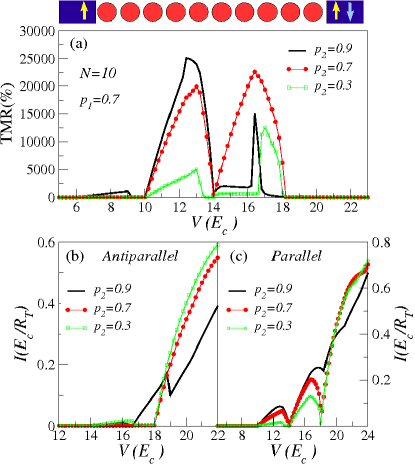
III Electrode polarization asymmetry
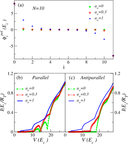
In the case of a single island the polarization asymmetry () induces spin accumulation for P orientation, which is absent if . While the dependence of the TMR on voltage does not change much qualitatively, its magnitude depends on the values of and , saturating at high voltages to . In arrays, to have different spin polarization in the electrodes breaks inversion symmetry and is expected to modify the spin potential profile created along the array. In particular, it can create a spin potential gradient not only when the electrodes polarizations are parallel, but also when they are antiparallel. The presence of such a gradient could modify notably the I-V curves of the AP configuration, allowing current flow below the metallic threshold and reducing the magnetoresistance in the voltage regime, where the peaks are observed.
Fig. 1(a) shows that the peaks in the TMR below the non-magnetic threshold ( for ) do not disappear when spin asymmetry is present. However, their shape is strongly modified. The values of the TMR have the same order of magnitude as observed when . Whether they are larger or smaller depends in a complicated way on the polarizations and on the voltage. Below and for fixed the current found for parallel arrangement increases with increasing without altering much the shape of the I-V curve, see Fig. 1 (c). With AP orientation peaks are observed in the I-V only when , see Fig. 1(b). Their shape is more irregular and their height notably reduced as compared to those found for P-orientation. The change in the shape of the TMR curve is mostly due to the change in the current for AP arrangement.
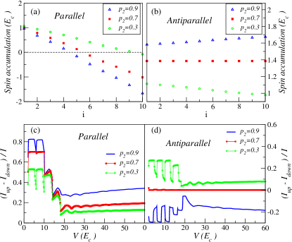
The differences in the current when compared with the case originate in the different spin gradient created through the array by the spin accumulation. The change in spin accumulation between the first and last island of the array is much larger when the electrode magnetizations are P than when they are AP, as shown in Fig. 2 (a) and (b). For P-orientation when the sign of the spin accumulation changes at the center of the array. With spin asymmetry this change of sign can happen or not and if it does, the change of sign will not happen at the array center in a generic case. For P arrangement and spin asymmetry the sign of the spin gradient does not depend on the asymmetry, but it is controlled by the orientation of the electrode magnetization. With AP orientation the spin accumulation can increase or decrease along the array depending on being larger or smaller than . At least for the cases that we have analyzed we have never found a change of sign in the spin accumulation.
The polarization asymmetry also modifies how much spin polarized it is the current. As it also happens in the single island case, the current in the AP-arrangement can be spin polarized only if , with the polarization sign depending on being smaller or larger than , see Fig. 2(d). For P-orientation it depends on the values of the electrode polarizations but does not change sign, as seen in Fig. 2(c). At high voltages the spin polarization saturates to
| (7) |
with upper and lower signs corresponding to P and AP configurations respectively.
IV Dimensionality of the array
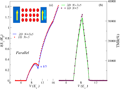
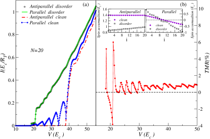
As shown in nosotroshuge10 to increase the length of a one-dimensional array placed between ferromagnetic electrodes from to or larger has an enormous impact on the I-V curves and on the TMR. Thus it is sensible to ask what does it happens if we increase the width of the array to become two-dimensional. For simplicity we assume an square-lattice array, see inset in Fig. 3. The current through metallic two-dimensional clean arrays (no charge disorder) is reasonably well described by assuming that the different rows conduct in parallelnosotros2D10 . If this is true also in the presence of spin accumulation no much change would be expected in the magnetoresistance because the current for both P and AP would be given by that of a one dimensional array multiplied by the number of rows. The validity of this approximation is confirmed in Fig. 3 where the TMR and the I-V curve for parallel arrangement for a 1D N=5 array and for a 2D one (three rows of 5-particles length) are compared. The agreement between the I-V curves is very good, once the 2D-array I-V has been divided by the number of rows. Minor differences are found around the metallic threshold ( for ). As expected the TMR of the 2D arrays follows very well the one of the 1D array. A small difference is only seen at the top of the peak. The TMR is more sensitive to small changes in the current of the AP-configuration (not shown), as this one is much smaller and enters into the denominator.
V Temperature
The high values of the TMR at the peaks are expected to be quite sensitive to temperature. These values are associated with the small current which flows through the array below the non-magnetic threshold when the magnetizations are AP. Such a current extrapolates to zero at zero temperatures. Such vanishing current at low temperatures is associated with tunneling processes at the inner junctions with vanishing cost in energy. Increasing the temperature allows the tunneling event to happen. From Eq. 2 the tunneling rate of processes with zero energy cost increases linearly with the temperature. On a first approximation the current for AP orientation is expected to increases linearly with the temperature, while the current through an array with P magnetizations will be much less sensitive because the tunneling processes at the inner junctions have a finite energy gain provided by the spin potential gradient. Such dependencies would result in a TMR inversely proportional to the temperature. Confirmation of this dependence and on the different effect of the temperature for P and AP orientations is seen in Fig. 4.
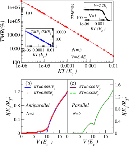
Note that the strong dependence of the TMR on the temperature is not a simple consequence of the weakening of Coulomb blockade. As shown in the top inset of Fig. 4 (a) the temperature dependence of the TMR corresponding to the single island case is much weaker at , because the tunneling processes involved are thermally activated, contrary to the zero energy cost relevant at the inner junctions of a long array with AP orientation. The different temperature dependence of the TMR for a single island and a long array is emphasized in the lower inset of the same figure.
VI Resistance disorder
The strong exponential dependence of the tunneling probability on the tunneling junction width makes that small differences on the distance between the nanoparticles result in large differences between the junction resistances. As a consequence resistance disorder is expected to play an important role in many devices based on nanoparticle arrays. In this section we show that the appearance of peaks in the I-V curves and the large values of the TMR are robust against resistance disorder.
Fig. 5 (a) shows the I-V curves for P and AP configurantions corresponding to an array with resistance disorder, being the junction resistances randomly assigned and varying between . Due to the different effect of the change in resistances for different voltages, these I-V curves are not compared with those found in clean arrays. Qualitatively, the main features displayed are the same in both cases. The I-V curve corresponding to AP arrangement shows a threshold voltage equal to the one found with non-magnetic electrodes, while the one for P-orientation is reduced. Peaks in the current are found at low voltages, below , the non-magnetic threshold, when the electrode magnetizations are parallel.
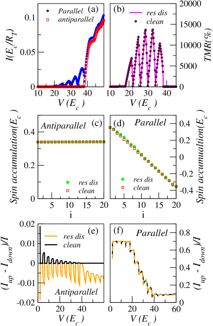
The TMR corresponding to these I-V curves is shown in Fig. 5 (b) where it is compared with the one found in the absence of resistance disorder. In the peaky region of voltages no differences are found between the TMR of both systems. The high values of the magnetoresistance are extremely robust against resistance disorder. As could be expected from the shape of the I-V curves in Fig. 5 (a) the spin accumulation, shown in Fig. 5 (c) and (d) is quite homogeneous through an array with AP orientation and decreases from left to right with P-orientation. As it happened when all the resistances are equal it changes sign at the center of the array, see Fig. 5 (d). For the voltages shown the spin accumulation differs very little when compared to the disorder free case. Interestingly, and opposite to what happened in uniform arrays, in the AP configuration, at high voltages an spin gradient is formed through the array what produces slight differences between the TMR of clean and disordered arrays at these voltages, not shown.
The spin polarization of the current is shown in Figs. 5 (e) and (f) for both magnetic orientations. In the P-arrangement it equals the one found when there is no resistance disorder. The situation changes with AP orientation. At high voltages a finite spin polarization is found in the disordered case, while it vanishes in the disorder-free array. The sign and dependence on voltage change for different realizations of the resistance disorder. The finite spin polarization found at low voltages is consequence of the finite temperature which allows a small current flow below the zero temperature threshold.
VII Charge disorder
Besides resistance disorder, charge disorder can be important in the devices. This type of disorder is unavoidable in many systems and specially important in self-assembled nanoparticle arrays. It arises as a consequence of nearby charge impurities which create random potentials in the nanoparticles. These random potentials can be described in terms of random background charges spread in the interval in each nanoparticle.
Charge disorder has a strong impact on the I-V curves of nanoparticle arrays even when the electrodes are non-magnetic. It modifies the threshold voltage, which now depends on the particular disorder configuration. In the limit of short range interactions discussed here, the threshold voltage, on average, is reduced to the half of the value found in a clean-array. Only half of the junctions (upward steps in potential) prevent the flow of charge. The voltages at which steps are found in the Coulomb staircase regime are also disorder dependent.
Fig. 6 (a) compares the I-V curves of clean and disordered arrays when the electrodes are magnetic and their polarizations are parallel or antiparallel. The I-V curves of the disordered arrays strongly differ when compared with the clean case. Most significatively, the strong dependence of the current on the magnetic orientation of the electrodes has disappeared. This is clearly seen in Fig. 6 (b) which shows a very small magnetoresistance. This figure is to be compared with Fig. 5 (b). Random charge disorder has reduced the TMR up to four orders of magnitude.
The large values of TMR found in clean arrays are a consequence of the spin potential gradient generated in the array present (absent) when the electrodes magnetizations are parallel (antiparallel). This potential gradient allows current to flow through the inner junctions. In the absence of such gradient, at zero temperature, the current vanishes at low voltages because, while tunneling does not cost energy it also does not gain it. The suppression of the TMR is not due to a reduction of the spin gradient. With charge disorder spin gradients are present, being even larger than in the clean case, see insets in Fig. 6 (b). They are finite, but much smaller with antiparallel configuration. However, contrary to the clean case, with disorder, tunneling through the junctions which prevent current (upward steps) costs energy. The change in potential due to spin accumulation is too small to overcome such energy cost or to modify significatively the tunneling rates through the junctions with downward steps in disorder potential.
VIII Long-range interactions
So far we have studied onsite interactions in which the interactions between the electrons are limited to those charges placed in the same conductor. This case is special because all the voltage drop happens at the contact junction. There is no polarization potential at the islands. This makes that at zero temperature and below the threshold corresponding to non-magnetic electrodes the current is maintained only by the spin accumulation. The potential drop at the inner junctions increases with increasing range of the interactions, as can be observed in Fig. 7 (a), where an exponentially decaying interaction, typical of capacitively coupled islands has been used. can be understood as a screening length.
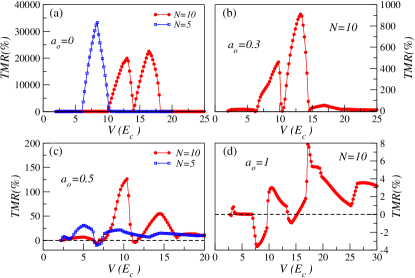
For finite range of the interactions and in the absence of charge disorder, once a charge has entered the array it is able to flow, even in the absence of charge gradient. The threshold voltage is strongly reduced and given by the voltage which allows an electron to enter the array or a hole to leave itnosotrosprb08 ; melsen97 . The role played by the spin accumulation on the transport is expected to decrease if the interactions are long range. The I-V curves corresponding to P and AP orientation, are shown in Fig. 7 (b) and (c) for the values of used in (a). The threshold voltage is similar for P and AP configurations, even if at voltages close to threshold the current is still highly suppressed, specially for the smaller values of . The potential drop at the junctions, and correspondingly the I-V curves shape are influenced both by the long-range of the interactions which affects the step width and height and by the spin accumulation responsible of the oscillations. For small oscillations in the current are observed when the electrode magnetizations are parallel, but they disappear for large .
The effect of increasing the range of the interaction on the TMR is plotted in Fig. 8. As expected the amplitude of the oscillations in the TMR is clearly reduced as increases. Note the different scale of the TMR axis in the plots. For and the TMR almost vanishes. On the other hand, as seen in Fig. 8 (c) the reduction of the TMR for a given interaction length depends strongly on the array length. As longer it is the array the reduction in the magnitude of the oscillations is weaker. This dependence appears because given an interaction length the polarization potential drops at the junctions between particles is larger for smaller .
IX Summary and Discussion
In summary, we have seen that the oscillations in the TMR and in the I-V curves are robust to most of the modifications that can appear in an experiment, when compared to the ideal case studied in nosotroshuge10 . In particular if source and drain have different spin polarizations the magnitude of the oscillations does not change much. The main effect induced by the polarization symmetry is a change in the peak shape and the appearance of peaks when the magnetizations are antiparallel. To go from a 1D to a 2D-square lattice array does not affect the TMR to a first approximation, while the current is increased following the number of rows in the 2D array. A similar situation is found in arrays with resistance disorder.
The amplitude of the oscillations and the TMR decreases with temperature so, the temperature should be kept as small as possible in an experiment as compared to the charging energy. Both large and small values of are convenient.
In many arrays the long-range part of the interaction is screened by mobile charges in neigbour conductors. If this does not happen the TMR can be suppressed with respect to the onsite interactions case. This effect is less important in long arrays. Thus, if the length of the interaction has to be taken into account the oscillations and large values of the TMR will be better observed in long arrays.
The most harmful effect is charge disorder. In some systems like self-assembled arrays this kind of disorder seems unavoidable because of charges quenched on the substracted. However, in other devices like epitaxially grown pillars the disorder will be probably less important, what makes them a better candidate to observe these effects.
We thank M.A. Garcia for useful discussions. Funding from Ministerio de Ciencia e Innovación through Grants No. FIS2008-00124/FIS, FPI fellowship and from Consejería de Educación de la Comunidad Autónoma de Madrid and CSIC through Grants No. CCG08-CSIC/ESP3518, PIE-200960I033 is acknowledged.
References
- (1) S.A. Wolf, D.D. Awschalom, R.A. Buhrman, J.M. Daughton, S. von Molnár, M.L. Roukes, A.Y. Chtchelkanova and D.M. Treger. Science 294, 1488 (2001).
- (2) M. Johnson. J. Phys. Chem. B 109, 14278 (2005).
- (3) C. Chappert, A. Fert, A. Van Dau and F. Nguyen. Nat. mat. 6, 813 (2007).
- (4) S. Bandyopadhyay and M. Cahay, Introduction to Spintronics, ed. CRC Press, New York (2008).
- (5) Single Charge Tunneling, NATO Advanced Studies Institute, Series B: Physics, edited by H. Grabert and M. H. Devoret (Plenum, New York) (1992).
- (6) M. Johnson and R.H. Silsbee, Phys. Rev. Lett. 55, 1790 (1985).
- (7) M. Julliére. Phys. Lett. A, 54, 225 (1975).
- (8) K. Ono, H. Shimada and Y. Ootuka. J. Phys. Soc. Jpn. 66, 1261 (1997).
- (9) J. Barnás and A. Fert, Phys. Rev. Lett. 80, 1058 (1998).
- (10) S. Takahashi and S. Maekawa, Phys. Rev. Lett. 80, 1758 (1998).
- (11) J. Barnás and A. Fert. Europhys. Lett. 44, 85 (1998).
- (12) A. Brataas, Y. V. Nazarov, J. Inoue and G.E.W. Bauer, Phys. Rev. B 59, 93 (1999).
- (13) H. Imamura, S. Takahashi and S. Maekawa, Phys. Rev. B 59, 6017 (1999).
- (14) K. Yakushiji, F. Ernult, H. Imamura, K. Yamane, S. Mitani, K. Takanashi, S. Takahashi, S. Maekawa and H. Fujimori. Nat. Mat. 4, 57 (2005).
- (15) I. Weymann, J. König, J. Martinek, J. Barnás and G. Schön. Phys. Rev. B 72, 115334 (2005).
- (16) N.S. Bakhalov, G.S. Kazacha, K.K. Likharev and S.I. Serdyukova. Sov. Phys. JETP, 68, 581 (1989).
- (17) E. Bascones, V. Estévez, J.A. Trinidad, and A.H. MacDonald, Phys. Rev. B 77, 245422 (2008).
- (18) A.A. Middleton and N.S. Wingreen. Phys. Rev. Lett. 71, 3198 (1993).
- (19) V. Estévez and E. Bascones, arXiv:1010.1141v1, Phys. Rev. B Rapid Comm., in press .
- (20) To use this function a broadening of the energy levels of order is assumed.
- (21) J.A. Melsen, U. Hanke, H.O. Müller, and K.A. Chao, Phys. Rev. B 55, 10638 (1997).
- (22) K. Elteto, E. G. Antonyan, T. T. Nguyen, and H. M. Jaeger, Phys. Rev. B 71, 064206 (2005).
- (23) V. Estévez and E. Bascones, arXiv:1011.0605v1.