Structural and magnetic properties of Co2MnSi thin films
Abstract
Co2MnSi (CMS) films of different thicknesses (20, 50 and 100 nm) were grown by radio frequency (RF) sputtering on a-plane sapphire substrates. Our X-rays diffraction study shows that, in all the samples, the cubic CSM axis is normal to the substrate and that there exist well defined preferential in-plane orientations. Static and dynamic magnetic properties were investigated using vibrating sample magnetometry (VSM) and micro-strip line ferromagnetic resonance (MS-FMR), respectively. From the resonance measurements versus the direction and the amplitude of an applied magnetic field we derive most of the magnetic parameters: magnetization, gyromagnetic factor, exchange stiffness coefficient and magnetic anisotropy terms. The in-plane anisotropy can be described as resulting from the superposition of two terms showing a two-fold and a four-fold symmetry without necessarily identical principal axes. The observed behavior of the hysteresis loops is in agreement with this complex form of the in-plane anisotropy
pacs:
76.50.+g, 78.35.+c, 75.30.Gw, 75.40.GbI Introduction
The strong spin polarization at the Fermi level of full Heusler alloys and their high Curie temperature make of them potential candidates for applications. Thus, these materials have been very recently inserted in spintronics devices films made of Co2MnSi full Heusler, which has a Curie temperature of 985 K [1,2], in order to be used in magnetic tunnel junctions (MTJs) containing one or two Co2MnSi electrodes and different barriers [3-8]. Heusler alloys were used as MTJ electrodes with an amorphous Al-oxide barrier [9-12] allowing for a tunnel magnetoresistance (TMR) ratio of at 2 K in a Co2MnSi/Al-O/CoFe structure [6]. A large TMR ratio, up to at 2 K and of at room temperature, was obtained with Co2MnSi used in TMJs with MgO barriers [13].
Despite this intense research activity on Heusler alloys, which is mainly focused on the way to improve the tunnel magnetoresistance, the static and dynamic magnetic properties of such alloys remain less explored [14-17]. The dynamics of these materials within the 1-10 GHz frequency range, which determines the high-speed response, is a key for their future technologic applications, especially in view of increasing data rates in magnetic storage devices. Moreover, the exchange stiffness constant which describes the strength of the exchange interaction inside Co2MnSi films is an important parameter from both fundamental and application points of view. Therefore, the aim of this paper is to investigate the static and dynamic magnetic properties of Co2MnSi thin films and their relations with their structure.
The paper is organized as follows: in section II we briefly present the preparation of the samples and their structural properties investigated by X-rays diffraction (XRD). Section III exposes their main static magnetic characteristics derived from our vibrating sample magnetometry (VSM) measurements. Section IV presents and discusses our dynamic measurements performed with the help of micro-strip ferromagnetic resonance (MS-FMR). In section V, conclusions are drawn.
II Sample preparation and structural properties
The Co2MnSi thin films (20, 50 and 100 nm in thickness) were
deposited on a-plane sapphire substrate by UHV-magnetron rf-sputtering
using pure Ar at a pressure of mbar as sputter gas.
The base pressure of the sputtering system was mbar,
the sputtering rate was 0.03 nm.s-1 for Co2MnSi and 0.025
nm.s-1 for the previously deposited vanadium seed underlayer.
During the deposition the temperature of the substrates was kept constant
at C. Heusler alloy targets with a diameter
of 10 cm were cut from single phase, stoichiometric ingots prepared
by high frequency melting of the components in high purity graphite
crucibles. The Al2O3 sapphire a-plane substrate was, as
mentioned above, preliminarily covered with a 5 nm thick vanadium-seed-layer
in order to induce a high quality growth of the Heusler compound.
After cooling them down to room temperature all the films were subsequently
covered by a 5 nm thick gold layer protecting them against oxidation.
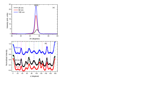
XRD measurements were performed using a Four-Circle diffractometer in Bragg-Brentano geometry in order to obtain patterns and -scans, operating at 40 kV and 40 mA, and using a Cu X-rays source ( nm). In all the films, the pattern (Figure 1a) indicates that a -type cubic axis is normal to the sample plane. The Co2MnSi deduced cubic lattice constant (e.g.: Å for the 100 nm thich sample) is in good agreement with the previously published value (5.654 Å) [2]. The samples behave as fiber textures containing well defined zones showing significantly higher intensities, as shown in Figure 1b, which represents -scans at (here, is the declination angle between the scattering vector and the direction normal to the film, is the rotational angle around this direction). The regions related to the observed maxima correspond to orientation variants which can be grouped into four families. Two of them were observed in a previous study [18, 19] concerning thin films of a neighboring Heusler compound, Co2MnGe, prepared using an identical protocol: in the first one the threefold or axis is oriented along the c rhombohedral direction of the sapphire substrate, thus defining two kinds of distinct domains respectively characterized by their [001] axis inclined at or at with respect to this orientation. The second family is rotated by from the first one and also contains two variants. In addition, we observe a third family consisting in domains with their axis along c and a fourth one with their axis normal to c. This distribution into 6 kinds of domains does not appreciably vary from sample to sample, as shown on Figure 1b. This difference in the structure between the Co2MnSi and Co2MnGe films probably arises from the variation of the lattice mismatch.
III Magnetic properties
III.1 Static magnetic measurements
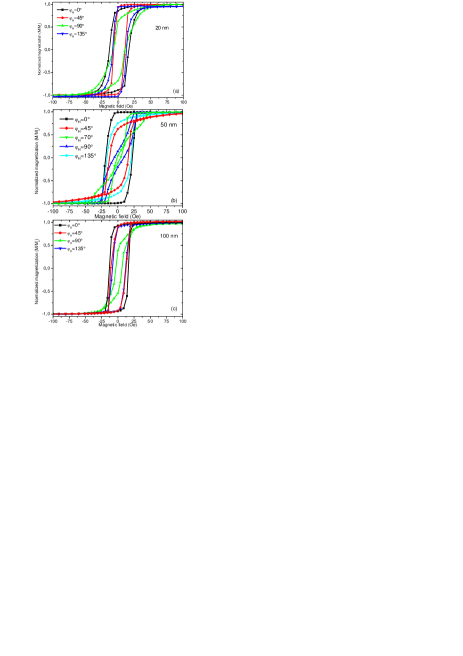
For all the samples the hysteresis curves were studied at room temperature
with an in-plane magnetic field applied along various orientations,
as shown in Figure 2 ( is the angle between and
the -axis of the substrate). The variations of the reduced remanent
magnetization () as function of are also
depicted in Figure 4, in view of comparison with other results discussed
in the next section. For any given direction of the applied field
the shape of the hysteresis loop is sample dependent, suggesting significant
differences in the amplitudes and in the principal directions describing
the in-plane anisotropy. Let us briefly discuss the case of the 50
nm film: as shown on Figure 2b, when lies along c ()
a typical easy axis square-shaped loop is observed, with a full normalized
remanence () and a coercive field of 20 Oe. As
increases decreases and the hysteresis
curve tends to transform into a hard axis loop. When
reaches its shape becomes more complicated: it consists
into three smaller loops. A further increase of jH restores an almost
rectangular shape. Notice the observed difference between orthogonal
directions ( vs
or: vs ) which
prevents a simple interpretation based on a four-fold in-plane anisotropy.
Our data qualitatively agree with a description of the in-plane anisotropy
in terms of an addition of four-fold and two-fold contributions with
slightly misaligned easy axes.
Figures 2a and 2c show a series of hysteresis loops related to the other films: here again, they qualitatively agree with the above description, but with different relative contributions and orientations of the two-fold and of the four-fold anisotropy terms. At evidence, a quantitative estimation of the pertinent in-plane anisotropy terms monitoring the dynamic properties presented in the next section cannot be derived assuming hysteresis behaviour based on the coherent rotation model. However, as discussed in the following, this model provides a satisfactory account of the angular variation of .
| (nm) | (µerg.cm-1) | (kOe) | (Oe) | (Oe) | (deg.) | (deg.) | |||||
| 20 | 11 | 20 | 72 | 0 | 45 | ||||||
| 50 | 2.87 | 11.35 | 26 | 88 | -13 | 0 | |||||
| 100 | 2.56 | 11.6 | 16 | 48 | 0 | 45 | |||||
III.2 Dynamic magnetic properties
The dynamic magnetic properties were scrutinized using with the help of a previously described MS-FMR [18, 19] setup. The resonance frequencies are obtained from a fit assuming a lorentzian derivative shape of the recorded spectra. As in ref. [18], we assume a magnetic energy density which, in addition to Zeeman, demagnetizing and exchange terms, is characterized by the following anisotropy contribution:
(1)
In the above expression, and
respectively represent the out-of-plane and the in-plane (referring
to the -axis of the substrate) angles defining the direction of
the magnetization ; and stand
for the angles of the uniaxial axis and of the easy fourfold axis,
respectively, with this -axis. With these definitions
and are necessarily positive. As in ref. [18], it is
convenient to introduce the effective magnetization ,
the uniaxial in-plane anisotropy field
and the fourfold in-plane anisotropy field .
For an in-plane applied magnetic field , the studied model provides the following expression of the frequencies of the experimentally observable magnetic modes:
For normal to the sample plane, large magnetic fields are applied (enough to allow for ) and thus the magnetic in-plane anisotropies can be neglected. Therefore, the frequency linearly varies versus H as:
(3)
In the above expressions the gyromagnetic factor is related to the effective Lande factor g through: s-1.Oe-1. The uniform mode corresponds to . The other modes to be considered (perpendicular standing spin waves: PSSW) are connected to integer values of : their frequencies depend upon the exchange stiffness constant and upon the film thickness .
For all the films the magnetic parameters at room temperature were derived from MS-FMR measurements.
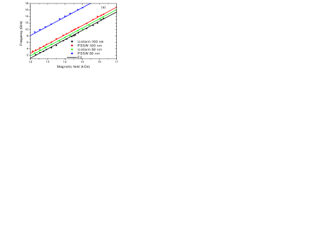
III.2.1 Gyromagnetic g-factor and spin wave stiffness
In perpendicular configuration the MS-FMR technique allows for deriving the values of and of from the variation of the resonance frequency versus the magnitude of the applied field using equation (3). The MS-FMR field-dependences of the resonance frequencies of the uniform and of the PSSW modes are shown on Figure 3 for the 50 nm and the 100 nm thick samples. The frequencies vary linearly with . The PSSW mode shows a frequency higher than the uniform one, by an amount independent of , as expected from the studied model. The derived value of is independent of the sample: . It is in good agreement with previous determinations [15]. The effective demagnetizing field slightly increases versus the sample thickness but remains close to the saturation magnetization (12200 Oe) given by Hamrle et al. [20]: it is reported in Table I. The best fits for the observed PSSW are obtained using erg.cm-1 and erg.cm-1 for the 50 nm and the 100 nm thick films respectively, in good agreement with the result published by Hamrle et al.( erg.cm-1) [20].
III.2.2 In-plane anisotropies
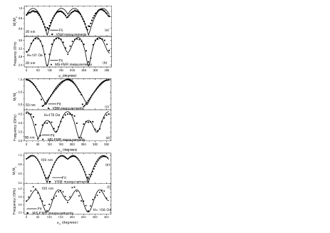
Figures 4b, 4d and 4f illustrate the experimental in-plane angular dependence of the frequency of the uniform mode in the 20, 50 and 100 nm thick films, compared to the obtained fits using equation (2). For all the samples, the obtained values of the magnetic parameters corresponding to the best fits are reported in Table I.
In all the investigated films the c-axis of the substrate coincides with a principal direction of the four-fold magnetic anisotropy: it defines a hard axis () except, surprisingly, in the 50 nm sample for which it defines an easy axis (). The directions of the principal axes of the two-fold anisotropy are sample dependent. The observed variations of the in-plane magnetic anisotropy are not clearly related either to the thickness or to the crystallographic texture (which does not significantly change). During the preparation of the films uncontrolled parameters presumably induce different stress conditions giving rise to changes in the magnetic anisotropy. Finally, it is interesting to notice that the set of in-plane magnetic anisotropy parameters deduced from the in-plane angular dependence of the magnetic resonance for the 20 nm, 50 nm and 100 nm thick samples allows for a good fit of the angular variation of the normalized static remanence calculated with the help of the coherent rotation model, as shown in Figures 4. This variation only depends on , and .
It results from the present study and from our previous ones [18, 19] that the growth of Heusler thin films on sapphire substrates is complex and depends on the conditions of the sample preparation. Therefore the magnetic properties cannot be tuned rigorously.
IV Conclusion
Co2MnSi films of thicknesses varying from 20, 50 and 100 nm were prepared by sputtering on a -plane sapphire substrate. They show practically identical crystallographic textures, as revealed by our X-rays diffraction studies, with a cubic axis normal to the film plane and with a well defined manifold of in-plane orientations referring to the -axis of the substrate. The micro-strip ferromagnetic resonance gives access to effective g factors which do not differ from each other and to effective demagnetizing fields which are close to the magnetization at saturation and which slightly increase with the sample thickness. In addition, this technique allowed us for evaluating the exchange stiffness constant which, as expected, was found not to significantly depend on the studied sample. The in-plane anisotropy was investigated through the study of the dependence of the resonance frequency versus the orientation of an in-plane applied magnetic field: it presents two contributions, showing a four-fold and a two-fold axial symmetry, respectively. A principal four-fold axis parallel to is always found, but it can be the easy or the hard axis. Depending on the studied film the two-fold axes can be misaligned with the four-fold ones. The angular dependence of the remanent normalized magnetization, studied by VSM and analyzed within the frame of a coherent rotation model, is in agreement with these conclusions. The general magnetic behavior is similar to the previously published one observed in Heusler Co2MnGe films [18, 19]. Apparently, there is no simple relation between the observed dispersion of the in-plane anisotropy parameters and the thickness or the crystallographic texture of the samples.
References
- (1) [1] R. J. Soulen Jr., J. M. Byers, M. S. Osofsky, B. Nadgorny, T. Ambrose, S. F. Cheng, P. R. Broussard, C. T. Tanaks, J. Nowak, J. S. Moodera, A. Barry, and J. M. D. Coey, Science 282, 85 (1998).
- (2) [2] P. J. Webster, J. Phys. Chem. Solids 32, 1221 (1971)
- (3) [3] J. Schmalhorst, S. Kämmerer, M. Sacher, G. Reiss, A. Hütten, and A. Scholl, Phys. Rev. B 70, 024426 (2004).
- (4) [4] Y. Sakuraba, J. Nakata, M. Oogane, H. Kubota, Y. Ando, A. Sakuma, and T. Miyazaki, Japan J. Appl. Phys. 44, L1100 (2005).
- (5) [5] M. Oogane, Y. Sakuraba, J. Nakata, H. Kubota, Y. Ando, A. Sakuma, and T. Miyazaki, J. Phys. D: Appl. Phys. 39, 834 (2006).
- (6) [6] Y. Sakuraba, M. Hattori, M. Oogane, Y. Ando, H. Kato, A. Sakuma, T. Miyazaki, and H. Kubota, Appl. Phys. Lett. 88, 192508 (2006).
- (7) [7] K. Inomata, N. Ikeda, N. Tezuka, R. Goto, S. Sugimoto, M. Wojcik, and E. Jedryka, Sci. Technol. Adv. Mat. 9, 014101 (2008).
- (8) [8] T. Ishikawa, S. Hakamata, K. Matsuda, T. Uemura, and M. Yamamoto, J. Appl. Phys. 103, 07A919 (2008).
- (9) [9] C. T. Tanaka, J. Nowak and J. S. Moodera, J. Appl. Phys. 86, 6239 (1999)
- (10) [10] S. Kämmerer, A. Thomas, A. Hütten and G. Reiss, Appl. Phys. Lett. 85, 79 (2004)
- (11) [11] A. Conca, S. Falk, G. Jakob, M. Jourdan and H. Adrian, J. Magn. Magn. Mater. 290–291, 1127 (2004)
- (12) [12] H. Kubota, J. Nakata, M. Oogane, Y. Ando, A. Sakuma and T. Miyazaki, Japan. J. Appl. Phys. 43 L984 (2004)
- (13) [13] S. Tsunegi, Y. Sakuraba, M. Oogane, K. Takanashi, Y. Ando, Appl. Phys. Lett. 93, 112506 (2008).
- (14) [14] Y. Liu, L. R. Shelford, V. V. Kruglyak, R. J. Hicken, Y. Sakuraba, M. Oogane, and Y. Ando, Phys. Rev. B 81, 094402 (2010)
- (15) [15] B. Rameev, F. Yildiz, S. Kazan, B. Aktas, A. Gupta, L. R. Tagirov, D. Rata, D. Buergler, P. Gruenberg, C. M. Schneider, S. Kämmerer, G. Reiss, and A. Hütten, phys. stat. sol. (a) 203, 1503 (2006)
- (16) [16] R. Yilgin, M. Oogane, Y. Ando, T. Miyazaki, J. Mag. Mag. Mat. 310, 2322 (2007)
- (17) [17] O. Gaier, J. Hamrle, S. J. Hermsdoerfer, H. Schultheiß, B. Hillebrands, Y. Sakuraba, M. Oogane, and Y. Ando, J. Phys. D: Appl. Phys. 43 (2010) 193001
- (18) [18] M. Belmeguenai, F. Zighem, Y. Roussigné, S-M. Chérif, P. Moch, K. Westerholt, G. Woltersdorf, and G. Bayreuther Phys. Rev. B79, 024419 (2009).
- (19) [19] M. Belmeguenai, F. Zighem, T. Chauveau, D. Faurie, Y. Roussigné, S-M. Chérif, P. Moch, K.Westerholt and P. Monod, J. Appl. Phys. 108, 063926 (2010)
- (20) [20] J. Hamrle, O. Gaier, Seong-Gi Min, B. Hillebrands, Y. Sakuraba and Y. Ando, J. Phys. D: Appl. Phys. 42, 084005 (2009)