Low frequency noise characteristics of sub-micron magnetic tunnel junctions
Abstract
We report that low frequency (up to 200 kHz) noise spectra of magnetic tunnel junctions with areas 10-10cm2 at 10 Kelvin deviate significantly from the typical behavior found in large area junctions at room temperature. In most cases, a Lorentzian-like shape with characteristic time between 0.1 and 10 ms is observed, which indicates only a small number of fluctuators contribute to the measured noise. By investigating the dependence of noise on both the magnitude and orientation of an applied magnetic field, we find that magnetization fluctuations in both free and reference layers are the main sources of noise in these devices. At small fields, where the noise from the free layer is dominant, a linear relation between the measured noise and angular magnetoresistance susceptibility can be established.
I INTRODUCTION
Magnetic tunnel junctions (MTJs) are currently used for information readout in disk drives Wood (2009), and for high sensitivity magnetic field sensors Egelhoff et al. (2009), and could be used in future technologies such as spin random access memory Katine and Fullerton (2008). For all these applications, the noise generated at the MTJs is a crucial factor limiting their ultimate performance. Besides the ubiquitous frequency independent thermal and shot noise present in MTJs, frequency dependent noise sources such as charge trapping in the oxide barrier Nowak et al. (1999) and thermally excited magnetization fluctuations and domain wall oscillations Ingvarsson et al. (2000) have been identified. For MTJs with areas larger than a few square microns, these noise sources usually exhibit a frequency dependence due to ensemble averaging of many individual fluctuators Liu and Xiao (2003); Jiang et al. (2004); Ren et al. (2004); Nor et al. (2006); Guo et al. (2009). In that case the magnitude of the noise is related to the resistance susceptibility as predicted by the fluctuation-dissipation theorem which only applies in thermal equilibrium Ingvarsson et al. (2000). However, as the dimensions of MTJs are reduced to the single domain range, the applicability of ensemble averaging and the fluctuation-dissipation relation are both under question.
In this work, we report on measurements of low frequency noise (up to 200 kHz) of single domain MTJs with areas 10-10cm2 at a temperature of 10 Kelvin. Our results show that for MTJs of this size, the dominant source of low frequency noise are magnetization fluctuations of both free and reference layers. For magnetic fields, , well below the pinning field of the reference layer, , noise from the free layer dominates, and a linear relation between noise magnitude and angular magnetoresistance (MR) susceptibility, (the derivative of magnetoresistance with respect to magnetic field orientation ), is observed. As increases and becomes comparable to , noise originating from magnetic fluctuations of the reference and free layer become comparable, and the linear relation between noise and no longer holds.
II EXPERIMENT
We use MTJs with the following stack composition (in ): buffer-layer/PtMn(175)/synthetic-antiferromagnet- pinned-layer (SAF)/MgO(9.5) /Fe(5) /Co60Fe20B(10) / Ru(100)/capping-layer (see Ref. Guan et al. (2009) for fabrication details). Devices are patterned into nanopillars with dimensions 100150 nm, where the easy axis of the free layer is nominally collinear with the pinning direction of the reference layer. The devices are cooled down to 10 K and can be rotated to any angle with respect to an applied in-plane magnetic field. The setup for the noise measurements is shown in the inset to Fig. 1 (a). The system has been calibrated using metal film resistors as sources of thermal noise and we have observed an almost flat spectrum with small roll-off that can be accurately modeled by a stray capacitance of 360 pF due to the cryostat wiring and limited amplifier bandwidth. The resolution of this setup is better than 0.3 nV/Hz1/2 with one minute of averaging. Background measurements at 0 dc current are always subtracted from the raw data. The data presented here is for a single device, but similar results were obtained for two devices.
III RESULTS AND DISCUSSION
III.1 Noise as a function of magnetic field
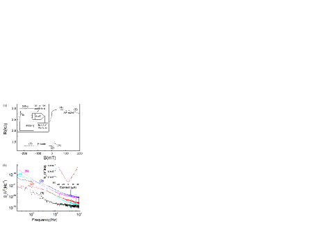
Fig. 1 (a) shows the hysteresis loop along the easy axis using (flowing from the free to the reference layer). Typical spectra at each of the labeled regions of Fig. 1 (a) are shown in Fig. 1 (b). We observe that the spectra do not agree with behavior, but can be described by a Lorentzian behavior with characteristic timescales from 0.1 to 10 ms, indicating that only a small number of fluctuators contribute to the measured noise Dutta et al. (1979). At large negative fields (region 1), where the field is parallel to the magnetic moments of both the free and the reference layers, the spectrum becomes almost flat above 70 kHz. The average noise between 70 and 90 kHz as a function of current is shown in the inset of Fig. 1 (b), and is close to the expected thermal and shot noise given by
| (1) |
where R is the device resistance and is the thermal energy. As B approaches zero, (region 2) and the free layer becomes bistable, the noise gradually increases up to the point where a sudden jump to an intermediate resistance state occurs, accompanied by an order of magnitude increase in noise (region 3). Once the free layer completely switches to the antiparallel (AP) state (region 4), the total noise power decreases and the Lorenzian corner frequency shifts towards lower frequency. At large positive fields (region 5), the resistance decreases since becomes comparable to , and starts to depin the layers within the SAF. The noise shows a more -like behavior, indicating that the decoupling of the SAF layer produces a large number of uncorrelated fluctuations with different energy scales Dutta et al. (1979).
III.2 Noise as a function of magnetic field orientation
By varying the orientation of an in-plane magnetic field that satisfies (where is the free layer anisotropy field) it is possible to smoothly rotate the magnetic moment of the free layer. Fig. 2 (a) shows the measured resistance as a function of (the in-plane angle between and nominal easy axis) for three values of . The solid lines represent fits to the equation Sun and Ralph (2008)
| (2) |
where and are the resistance of the parallel and antiparallel state respectively, and , the angle difference between the free and reference layer magnetic moments, is a function of . The functions and are found by minimizing the energies of the free and reference layers, which in the simplest approximation are given by B.D.Cullity and C.D.Graham (2008)
| (3) | |||
| (4) |
Here, () and () are the magnetization and volume of the free (reference) layer. The best fit with parameters mT and mT accurately describes the device behavior at mT and mT but shows slight disagreement at mT, where the resistance displays sudden changes at particular field orientations, likely indicating that is not large enough to overcome pinning fields from defects.
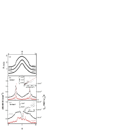
We integrate the noise spectrum over the measured frequency range from 6 Hz to 200 kHz for each . The average noise voltage as a function of field angle for mT ( mT) is shown in Fig. 2 (b) [Fig. 2 (c)]. For mT, is very similar to obtained from Fig. 2 (a). Both curves show minima at =0 and (P and AP states) and maxima close to and . Several spikes that appear in both the noise and also indicate that excess noise is produced at field directions where sudden changes in the magnetic moment orientation occur. It is possible that irregular nanopillar edges, material defects, and grain boundaries provide pinning directions at which the magnetic moment is more difficult to rotate; a larger change in field orientation is required to unpin and rotate the magnetic moment resulting in sudden jumps in resistance. Just before depinning occurs, thermal excitations are able to excite the magnetic moment between the pinned and the “free” orientations, causing enhanced noise with strongly Lorenzian behavior (data not shown here).
From the inset of Fig. 2 (b), a linear relation between and is phenomenologically established as
| (5) |
Here, =3.210-7 Hz-1/2 represents the nonmagnetic background noise, while the calculated thermal and shot noise level is 2.510-7 Hz-1/2 at 5 and temperature of 10 K. The slope k of the fitting line in the inset of Fig. 2 (b) is equal to 1.610-6 rad/Hz1/2. The linear relation established here between and is similar in spirit to the linear relation obtained by Ren Ren et al. (2004) between the magnetic-field noise and .
For larger fields, such as mT, [see Fig. 2 (c)], the noise minima at disappears, the similarity between the noise and becomes less apparent (particularly around ), and the linear relation between noise and does not hold [inset to Fig. 2 (c)]. As discussed in the previous section, when the field opposing the reference layer becomes comparable to , the free layer is no longer the dominant source of noise Ozbay et al. (2009). Although the fluctuations of the reference layer do not cause a clearly observable change in the resistance, they can dominate the spectrum at : whereas the free layer is stabilized by the applied field, larger fields will continue to destabilize the SAF layers, providing additional mechanisms for fluctuations to occur.
IV CONCLUSION
In summary, we have measured low frequency noise of sub-micron MgO-based MTJs at 10 K. In most cases, the noise spectra are Lorentzian in character, indicating that noise is produced by a few magnetic fluctuators which are thermally excited in the free layer magnetic electrode. We experimentally established a linear relation between normalized noise and the angular magnetoresistance susceptibility for , where noise is dominated by magnetization fluctuations of the free layer, and observed that for , destabilization of the reference layer due to SAF layer decoupling leads to a transition from free layer to reference layer dominated noise.
Acknowledgements.
We wish to thank Jonathan Sun (IBM-MagIC MRAM Alliance, IBM T.J. Watson Research Center at Yorktown Heights, NY) for providing us with the devices and for helpful discussions. Part of this work was supported by the Army Research Office (Grant No. W911NF-08-0299).References
- Wood (2009) R. Wood, J. Magn. Magn. Mater. 321, 555 (2009).
- Egelhoff et al. (2009) W. F. Egelhoff Jr., P. W. T. Pong, J. Ungurisb, R. D. McMichael, E. R. Nowak, A. S. Edelsteind, J. E. Burnetted, and G. A. Fischer, Sens. Actuators, A 155, 217 (2009).
- Katine and Fullerton (2008) J. A. Katine and E. E. Fullerton, J. Magn. Magn. Mater. 320, 1217 (2008).
- Nowak et al. (1999) E. R. Nowak, M. B. Weissman, and S. S. P. Parkin, Appl. Phys. Lett. 74, 600 (1999).
- Ingvarsson et al. (2000) S. Ingvarsson, G. Xiao, S. S. P. Parkin, W. J. Gallagher, G. Grinstein, and R. H. Koch, Phys. Rev. Lett. 85, 3289 (2000).
- Liu and Xiao (2003) X. Liu and G. Xiao, J. Appl. Phys. 94, 6218 (2003).
- Jiang et al. (2004) L. Jiang, E. R. Nowak, P. E. Scott, J. Johnson, J. M. Slaughter, J. J. Sun, and R. W. Dave, Phys. Rev. B 69, 054407 (2004).
- Ren et al. (2004) C. Ren, X. Liu, B. D. Schrag, and G. Xiao, Phys. Rev. B 69, 104405 (2004).
- Nor et al. (2006) A. F. M. Nor, T. Kato, S. J. Ahn, T. Daibou, K. Ono, M. Oogane, Y. Ando, and T. Miyazaki, J. Appl. Phys. 99, 08T306 (2006).
- Guo et al. (2009) F. Guo, G. McKusky, and E. D. Dahlberg, Appl. Phys. Lett. 95, 062512 (2009).
- Guan et al. (2009) Y. Guan, D. W. Abraham, M. C. Gaidis, G. Hu, E. J. O’Sullivan, J. J. Nowak, P. L. Trouilloud, D. C. Worledge, and J. Z. Sun, J. Appl. Phys. 105, 07D127 (2009).
- Dutta et al. (1979) P. Dutta, P. Dimon, and P. M. Horn, Phys. Rev. Lett. 43, 646 (1979).
- Sun and Ralph (2008) J. Z. Sun and D. C. Ralph, J. Magn. Magn. Mater. 320, 1227 (2008).
- B.D.Cullity and C.D.Graham (2008) B. D. Cullity and C. D. Graham, Introduction to Magnetic Materials (Wiley-IEEE Press, 2008).
- Ozbay et al. (2009) A. Ozbay, A. Gokce, T. Flanagan, R. A. Stearrett, E. R. Nowak, and C. Nordman, Appl. Phys. Lett. 94, 202506 (2009).