Exciton polarization, fine structure splitting and quantum dot asymmetry under uniaxial stress
Abstract
We derive a general relation between the fine structure splitting (FSS) and the exciton polarization angle of self-assembled quantum dots (QDs) under uniaxial stress. We show that the FSS lower bound under external stress can be predicted by the exciton polarization angle and FSS under zero stress. The critical stress can also be determined by monitoring the change in exciton polarization angle. We confirm the theory by performing atomistic pseudopotential calculations for the InAs/GaAs QDs. The work provides a deep insight into the dots asymmetry and their optical properties, and a useful guide in selecting QDs with smallest FSS which are crucial in entangled photon sources applications.
pacs:
73.21.La, 78.67.Hc, 42.50.-pThe recent successful demonstration Stevenson et al. (2006) of entangled photon emission from a biexciton cascade process Benson et al. (2000) in a single quantum dot (QD) represents a significant advance in solid state quantum information applications. The “on-demand” QD entangled photon source has fundamental advantages over traditional sources using spontaneous parametric down conversion process which are probabilistic Gisin et al. (2002). Furthermore, QD emitters can be driven electrically rather than optically, and therefore have many advantages in device applications Salter et al. (2010). However, it is still a big challenge in the generation of high-quality entangled photon pairs from QDs.
The key issue here is to suppress the fine structure splitting (FSS) [Fig. 1 (a)] of the monoexciton, which arises from the underlying asymmetry of the QDs. There have been many attempts to reduce the FSS in QDs, including thermal annealing Tartakovskii et al. (2004); Stevenson et al. (2006), choosing proper dot matrix materials He et al. (2008), and growing the dots in high symmetry directions Singh and Bester (2009). However, these methods can only reduce the FSS to the level of about 10 eV, which might still be too large to produce high-quality entangled photon pairs. It has been shown that the FSS can be effectively tuned by an external magnetic field Stevenson et al. (2006) and electric field Gerardot et al. (2007); Bennett et al. (2010). Perhaps a more convenient way to tune the FSS in a QD is via uniaxial stresses Seidl et al. (2006). Singh et al Singh and Bester (2010) showed that the FSS can be tuned to zero under uniaxial stress for an ideal QDs with symmetry. However, for a general QD, which has symmetry, there is a lower bound for the FSS when an external stress is applied. It was unclear which or what kind of QDs may have the smallest FSS lower bound under stress. Therefore, it is still an open question in selecting QDs that are suitable for entangled photon emitters.
The purpose of the letter is to establish a general relationship between the asymmetry in QDs, the exciton polarization angle and the FSS under uniaxial stress, therefore provides a useful guide in selecting QDs that have the smallest FSS lower bounds for applications such as entangled photon emitters. We show that QDs in which the exciton has polarization closely aligned along the [110] or [100] directions have the smallest FSS under stress. The critical stress can also be determined by monitoring the change in the exciton polarization angle. The theory is further confirmed through an atomistic empirical pseudopotential calculations for InAs/GaAs QDs.
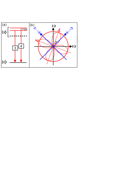
We start from a general understanding of the relation between the QD symmetry and exciton polarization angles shown in Fig. 1(b). An ideal InAs/GaAs QD has symmetry. Without spin-orbit coupling, the two bright exciton states belong to two different irreducible representations and . The polarizations of the two bright states are along the [100] and [010] directions respectively. When the spin-orbital interaction is included, the two bright states belong to irreducible representation Bester et al. (2003), therefore the polarizations of the emission lines should be exactly along the and directions. For a general dot, the symmetry is further lowered to owing to structural imperfections or alloy randomness Mlinar and Zunger (2009), the polarization angle will depart from the and directions, i.e., 0.
When uniaxial stress is applied, the exciton Hamiltonian can be written as,
| (1) |
where is the external stress direction, and is the magnitude of the stress. represent the Hamiltonian of an idea QDs with symmetry, whereas lower the dot symmetry to , due to local structure deformations, alloy distribution Mlinar and Zunger (2009) and interfacial effects Bester and Zunger (2005) etc. is the potential change due to the external stress. We neglect the higher-order terms. This is justified by atomistic pseudopotential calculations, which show that these terms are negligible up to 200 MPa. The eigenvectors of the two bright states of are and , with corresponding eigenvalues and , respectively. The energy levels are schematically shown in Fig. 1(a) in solid lines. The difference is the FSS. The other two states and are optically dark, also shown in Fig. 1(a) in broken lines. In the absence of an in-plane magnetic field, the coupling between the dark states and bright states is negligible. We therefore write the Hamiltonian in the space spanned by the two bright states,
| (2) |
where , . (=3, 4), and . Because the Hamiltonian has a time-reversal symmetry, all parameters can therefore be set to real values for simplicity. Diagonalization of the Hamiltonian yields eigenvalues,
| (3) |
where and . The eigenvectors of the two states are . Since all parameters are real, the two states are linearly polarized foo . We calculate for QDs under uniaxial stress ,
| (4) |
Because is a quadratic function of , the lower bound of FSS and the corresponding critical stress can be calculated analytically,
| (5) |
The polarization angle vs can be calculated from,
| (6) |
Obviously, changes with . At the critical stress , we have , where is the sign of . It is interesting to find that the polarization angle at the critical stress is independent of and , but only on the ratio of . Thus the values of , , and can be uniquely determined using the relationship between and , and the polarization angle at .
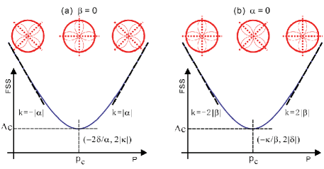
For a dot with symmetry, the external stress along the [110] and [10] directions would not change the symmetry of the dot. For a general dot, the symmetry of the dot is lowered to due to alloy distribution and structural asymmetry Mlinar and Zunger (2009); Bester and Zunger (2005), which change little under external stress. Therefore, for stress along the [110] and [10] directions, we have 0. Another special case arises when stress is applied along the [100] direction, for which we have =0 by symmetry. The results for these two special cases are schematically shown in Fig. 2 (a), (b) respectively. In Fig. 2(a), the change in FSS with is determined by , and the lower bound is determined by at . At , the polarizations are along the [100] or [010] directions whereas far away from , the polarizations are along the [110] or [10] directions. The results for shown in Fig. 2 (b) are totally different. In this case, the change in FSS with is determined by , and the lower bound is at . At , the polarization is along the [110] and [10] directions, whereas far away from , the polarization is rotated into the [100] and [010] directions. Therefore, the polarization angle of the emission lines can be used to determine the critical point in experiments. The above picture is also correct for QDs with symmetry, where , and the results in Fig. 2 (a) are then reduced to the results presented in Ref. [Singh and Bester, 2010].
The theory also provides a simple way to determine the FSS lower bound of a QD before applying the external stress. At , we have and polarization angle . It is easy to show that and . Thus by measuring the polarization angle and FSS at =0, we can uniquely determine the values of 2 and 2 which are the FSS lower bounds for the stress along the [110] ([10]) and [100] directions. For entangled photon source applications, or need to be smaller than 1 eV. Therefore our results provide a useful guide in selecting QDs for entangled photon sources, i.e., one should pick QDs for which the polarization angle is as closely aligned as possible to the [110] or [100] direction.
To confirm the above analysis, we perform numerical calculations of the FSS and polarization angle of InAs/GaAs QDs using an empirical pseudopotential method Wang and Zunger (1999); Williamson et al. (2000). We model the InAs/GaAs QDs by embedding the InAs dots into a 606060 8-atom GaAs supercell. To calculate the exciton energies and their FSS, we first have to obtain the single-particle energy levels and wavefunctions by solving the Schrödinger equation,
| (7) |
where is the total pseudopotential and is the local screened atomic potential at the equilibrium atom position obtained by minimizing the total strain energies under the given stress Singh and Bester (2010) using the valence force field method Keating (1966). is the spin-orbit interaction, and is the piezoelectric potential Bester et al. (2006). The single particle energy levels are calculated using a linear combination of bulk bands method Wang and Zunger (1999). The exciton energies are then calculated via many-particle configuration interaction (CI) method Franceschetti et al. (1999), in which the exciton wavefunctions are expanded in Slater determinants constructed from all confined electron and hole single-particle states.
| QDs | |||||||
| Lens (=0) | [110] | 0.36 | 0 | -8.46 | 0 | 47 | 0 |
| =20, =3.5 | [10] | -0.37 | 0 | -8.55 | 0 | -46 | 0 |
| [100] | 0 | -0.095 | -8.65 | 0 | 0 | 17.3 | |
| Lens () | [110] | 0.14 | 0 | -3.36 | -2.90 | 49 | 5.8 |
| =25, =3.5 | [10] | -0.14 | 0 | -3.36 | -2.86 | -47 | 5.7 |
| [100] | 0 | -0.047 | -3.38 | -2.90 | -62 | 6.8 | |
| Pyramid (=0.6) | [110] | 0.13 | 0 | -1.32 | -0.64 | 21 | 1.3 |
| =25, =3.5 | [10] | -0.13 | 0 | -1.41 | -0.61 | -22 | 1.2 |
| [100] | 0 | -0.048 | -1.32 | -0.69 | 14 | 2.6 | |
| Elongated (=0.6) | [110] | 0.14 | 0 | 2.76 | -0.72 | -40 | 1.4 |
| =26, | [10] | -0.14 | 0 | 2.73 | -0.78 | 38 | 1.6 |
| =20, =3.5 | [100] | 0 | -0.051 | 2.62 | -0.92 | -18 | 5.2 |
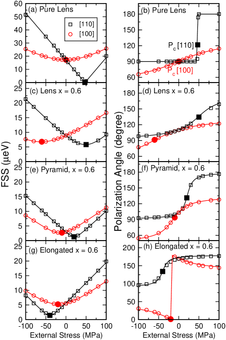
The change in FSS under external stress is purely an atomistic effect, because the macroscopic shapes of the dots change little (less than 0.1%) under such stresses and should not affect the FSS. Furthermore, we find that including piezoelectricity or not gives essentially the same results, suggesting that piezoelectricity is not responsible for the FSS change. In fact, the change in FSS is due to changes in the underlying atomic structure. We have calculated the FSS of more than 13 dots under external stresses along the [110], [10] and [100] directions. The behaviors of FSS are almost symmetric for stresses along the [110] and [10] directions, i.e., the effects of tensile stress along the [110] direction is almost identical to the effects of compression along the [10] direction. The results for some typical dots are shown in Fig. 3, whereas the geometry and other parameters of these dots are listed in Table. 1. In the left panels of Fig. 3, we plot the FSS vs along the [110] (black square) and [100] (red circle) directions. The solid lines are fitted from theory using Eq. (4). The right panels show the corresponding polarization angle vs where the solid lines are the theoretical predictions using Eq. (6). We use =0 (=0) for along [110] ([100]) direction. As can be seen, the agreement between numerical calculations and theory is remarkable.
(1) Pure InAs/GaAs QDs with symmetry. In Fig. 3 (a) we show the FSS vs along different directions for a pure lens-shaped QDs with base =20 nm and height =3.5 nm. When the stresses are directed along the [110] and directions, the FSS can be tuned exactly to zero Singh and Bester (2010). The polarization angle is constant (90∘) below = 47 MPa and jump to 180∘ after as shown in Fig. 3 (b). However, if the stress is along the direction, the FSS can not be tuned to zero, in agreement with previous results Singh and Bester (2010). The polarization angle rotates following Eq. (6) as seen in Fig. 3 (b). At , the polarization angle is 90∘. We also calculate pure pyramidal and elongated QDs, which do not have macroscopic cylindrical symmetry but still retain symmetry, and find similar features.
(2) Alloy In0.6Ga0.4As/GaAs QDs with symmetry. For alloy dots, the symmetry is lowered to . The FSS has lower bound under the uniaxial stress Singh and Bester (2010), as shown in Fig. 3 (c) (e) and (g), for different dot geometries and sizes. The corresponding parameters are summarized in Table 1. The stress dependence of the polarization angles is also in excellent agreement with theory as shown in Fig. 3 (d), (f) and (h) for the three dots. All three dots have polarization angle =135∘ at if the stress is along the [110] direction, and =90∘ (or 0∘) if the stress is along the [100] direction, as predicted by the theory. Among the three alloy dots, the lens-shaped QD [Fig. 3 (c)] has the largest lower bounds 7 eV at 62 MPa along the [100] direction. At =0, the lens-shaped QD has = 110∘, compared to = 103∘ for the pyramidal dot and 169∘ for the elongated dot. The polarization angle of the lens-shaped QD deviates from the [110] (or [10]) direction most, and hence has the largest FSS at , as predicted by the theory. We obtain similar results when the stress in along the [100] direction.
In the calculations, we find that is not very sensitive to the QD shape, but changes with alloy compositions. For example, for pure dots, 0.2 - 0.4 eV/MPa for along the [110] direction, whereas for In composition =0.6, reduces to 0.1 - 0.2 eV/MPa. also has similar features (for along the [100] direction), with 0.05 - 0.1 eV/MPa for pure dots, and 0.04 - 0.05 eV/MPa for alloy dots with =0.6. We also calculate alloy dots of the same geometry but with different alloy distributions Mlinar and Zunger (2009) and find that the alloy distribution does not significantly change the values of and . In contrast, , , and the polarization angle at =0, change dramatically from dot to dot, in agreement with recent experiments Favero et al. (2005). However, in all cases, the behaviors of the FSS and polarization angle under stress are in excellent agreement with our theoretical predictions.
To conclude, we have established a general relationship between the asymmetry in QDs, the exciton polarization angle, and the FSS under uniaxial stress. We showed that the FSS lower bound under external stress can be predicted by the polarization angle and FSS under zero stress. The critical stress can also be determined by monitoring the change in exciton polarization angle. The work therefore provides a useful guide in selecting QDs with smallest FSS which is crucial for entangled photon sources applications.
The authors thank A. J. Bennett for bringing Ref. Bennett et al., 2010 to our attention. LH acknowledges the support from the Chinese National Fundamental Research Program 2011CB921200 and National Natural Science Funds for Distinguished Young Scholars.
Note added: After submitted the paper, we became aware of Ref. Bennett et al., 2010. There, the exciton FSS of InAs/GaAs QDs is tuned via an electric field along the [001] direction, which has the same symmetry as applying stress along the [110] and [1-10] directions (i.e., the case of =0). Determining the degree of agreement between the present theory and the experiment of Ref. Bennett et al., 2010 is a promising avenue for future research.
References
- Stevenson et al. (2006) R. M. Stevenson et. al., Nature 439, 179 (2006).
- Benson et al. (2000) O. Benson et. al., Phys. Rev. Lett. 84, 2513 (2000).
- Gisin et al. (2002) N. Gisin et. al., Rev. Mod. Phys. 74, 145 (2002).
- Salter et al. (2010) C. L. Salter et. al., Nature 465, 594 (2010).
- Tartakovskii et al. (2004) A. I. Tartakovskii, et al., Phys. Rev. B 70, 193303 (2004).
- He et al. (2008) L. He, et al., Phys. Rev. Lett. 101, 157405 (2008).
- Singh and Bester (2009) R. Singh and G. Bester, Phys. Rev. Lett. 103, 063601 (2009).
- Gerardot et al. (2007) B. D. Gerardot, et al., Appl. Phys. Lett. 90, 041101 (2007).
- Bennett et al. (2010) A. J. Bennett, et al., Nat. Phys. 6, 947 (2010).
- Seidl et al. (2006) S. Seidl et. al., Appl. Phys. Lett. 88, 203113 (2006).
- Singh and Bester (2010) R. Singh and G. Bester, Phys. Rev. Lett. 104, 196803 (2010).
- Bester et al. (2003) G. Bester, et al., Phys. Rev. B 67, 161306 (2003).
- Mlinar and Zunger (2009) V. Mlinar and A. Zunger, Phys. Rev. B 79, 115416 (2009).
- Bester and Zunger (2005) G. Bester and A. Zunger, Phys. Rev. B 71, 045318 (2005).
- (15) The linear polarization is protected by the time-reversal symmetry. If the time-reversal symmetry is broken, the parameters are not always real and the polarization will become circular.
- Wang and Zunger (1999) L.-W. Wang and A. Zunger, Phys. Rev. B 59, 15806 (1999).
- Williamson et al. (2000) A. J. Williamson, L.-W. Wang, and A. Zunger, Phys. Rev. B 62, 12963 (2000).
- Keating (1966) P. N. Keating, Phys. Rev. 145, 637 (1966).
- Bester et al. (2006) G. Bester, et al., Phys. Rev. B 74, 081305(R) (2006).
- Franceschetti et al. (1999) A. Franceschetti, et al., Phys. Rev. B 60, 1819 (1999).
- Favero et al. (2005) I. Favero, et al., Appl. Phys. Lett. 86, 041904 (2005).