Undulation instabilities in the meniscus of smectic membranes
Abstract
Using optical microscopy, phase shifting interferometry and atomic force microscopy, we demonstrate the existence of undulated structures in the meniscus of ferroelectric smectic-C∗ films. The meniscus is characterized by a periodic undulation of the smectic-air interface, which manifests itself in a striped pattern. The instability disappears in the untilted smectic-A phase. The modulation amplitude and wavelength both depend on meniscus thickness. We study the temperature evolution of the structure and propose a simple model that accounts for the observed undulations.
pacs:
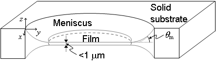
61.30.Jf, 61.30.Hn, 61.30.GdWhen in contact to a solid substrate, isotropic liquids form a meniscus whose properties are controlled by the well-established laws of capillarity and gravity rowlinson . Wetting of liquids on surfaces, for example, is of ubiquitous importance in many industrial fields and our everyday life experience. The case of complex liquids, such as liquid crystals (LC), is much more complicated because of the partial ordering of molecules. The molecular order breaks the rotationnal and/or translationnal symmetries of ordinary disordered liquids and imparts elastic properties. As a result, most physical properties become anisotropic. Studies of wetting of liquid crystals date back to the 70’s, and the more specific case of smectic free-standing films (FSF), or smectic membranes, was addressed more recently pieranski93 ; picano00 ; poniewierski02 . In contrast to isotropic liquids, where the meniscus profile is exponential (e.g. soap films), the meniscus in smectic-A (smA) FSF has a circular profile and forms a finite angle with the film (Fig. 1). The meniscus shape determines the film disjoining pressure oswpier , which governs its stability and is essential in many interesting phenomena, such as thinning transitions stoebe94 . The shape and structure of menisci also play a key role in capillary interactions between small solid objects trapped at fluid interfaces kral00 ; loudet05 ; oettel08 . When embedded in FSF, inclusions self-organize due to both film deformations and elastic distortions of the LC host poulin97 ; lubensky98 ; dolganov08 ; bohley08 .
The situation is even more complex in smectic-C (smC) or chiral smectic-C* (smC∗) phases oswpier ; degennes where the molecules are tilted with respect to the layer normal. Projection of the molecular axes onto the layer plane, defined as the -director, can vary in orientation and form modulated structures. Meyer and Pershan meyer73 described the so-called splay domains in the meniscus of smC∗ films, which were associated with surface-induced spontaneous polarization resulting in -director splay. Layer undulation was proposed as a reason for the observed patterns around solid inclusions in smA films conradi06 . Quite recently, Harth and Stannarius harth09 reported studies of modulated striped structures in the menisci at the film edge as well as around inclusions embedded in films. They interpreted the observed structures to -director distortions, consistent with splay domains. Nevertheless, in spite of a long history of studies meyer73 ; conradi06 ; harth09 , uncertainty still exists about the nature of these modulated structures.
In this paper we demonstrate that stripes observed in smC∗ meniscus are related to undulations of the smectic-air interface. The phenomenon resembles the formation of wrinkles at interfaces observed in various soft matter systems huang07 ; vandeparre10 ; holmes10 , which attracts considerable attention. The observed modulation crucially depends on temperature and meniscus thickness. A simple model, based on dilation-induced strain applied to the smectic layers, is shown to be consistent with the experimental results.
We used a variety of experimental methods, namely polarized light microscopy, phase shifting interferometry (PSI) and atomic force microscopy (AFM). Experiments were performed on several compounds, including ferroelectric materials ZLI-3488 lalanne91 , SCE-9 and SCE-12 (Merck, England). Films in the smC∗ and smA phases were prepared on a hole in a thin glass plate (Fig. 1). After preparation, the films were kept at a constant temperature for several hours to ensure the relaxation of the meniscus shape. Temperature was controlled by a Mettler heating stage.
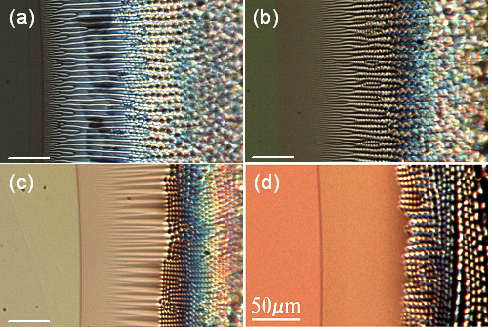
Figure 2 shows the characteristic patterns in the film meniscus. Nearly vertical lines are the boundaries between the film and the meniscus (respectively, the left and right part in each figure). The meniscus thickness increases from left to right. In the SmC∗ phase, various modulated structures develop only in the meniscus and not in the film. First, a system of branched and then parallel stripes is formed [Fig. 2(a-c)]. We will denote this modulated structure as a 1D pattern. In the thick part of the meniscus, a 2D pattern is observed. It may be described as rows of square domains that appear for a well-defined meniscus thickness 2dnet . A crossover region exists between the 1D and 2D patterns [Fig. 2(b)]: while the stripes are still visible, a secondary modulation develops along the film thickness gradient. The period of the stripes and the size of the squares increase with meniscus thickness. As already thoroughly described in harth09 , the meniscus texture is independent of the chiral nature of the considered compounds but varies strongly with temperature. We remind here that, in free-standing films, the smC∗ structure can exist above the bulk smC∗-smA transition temperature, , due to surface ordering oswpier . On heating close to (Fig. 2), the contrast of the stripe pattern decreases gradually. Just above , residual stripes remain in the meniscus [Fig. 2(c)]. They eventually disappear completely upon further heating while the square pattern partially remains [Fig. 2(d)]. The 2D pattern fades away in a stepwise manner: the squares disappear row by row, following an unzipping-like mechanism, starting from the thinner regions. Well above , square domains are no longer present and the whole meniscus becomes defect-free.
On cooling back to the smC∗ phase, the same patterns reappear in reverse order. The observed phenomena are fully reproducible over heating/cooling cycles. At constant temperature, all the above structures survive for many days as long as the film is stable.
To clarify the nature of the observed structures, we used Phase Shifting Interferometry (PSI) to probe the smectic-air meniscus profile, , with a resolution of a few nanometers. The principles of PSI and the experimental setup were described elsewhere loudet06 ; harasaki ; robinson .
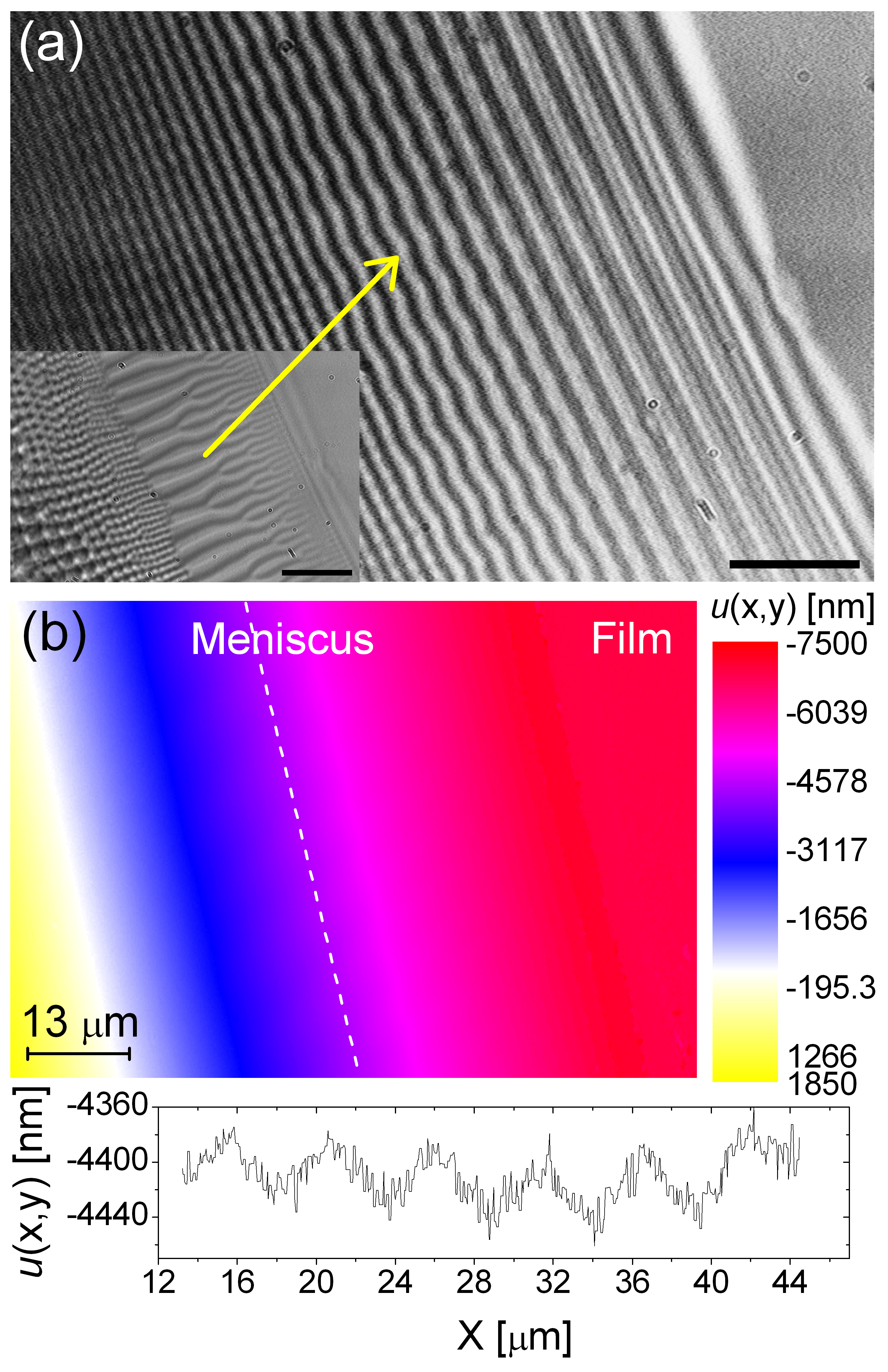
Figure 3(a) shows an interferogram of a smC∗ meniscus. The main feature of this image is that interference fringes are not straight but wavy in the stripes area. Therefore, the meniscus is not smooth (as in smA) but rather undulated in this area. The corresponding height profile , reconstructed from a series of interferograms, is presented in Fig. 3(b). The meniscus rises about m above the flat film. The oblique dashed line marks the location of the broadest wrinkles in the inset of Fig. 3(a) while the bottom graph exhibits the associated profile. In this region, undulations occur with amplitude around nm and wavelength m. The existence of wave-like fringes is directly correlated to the presence of stripes: on heating above , as the stripes disappear, the fringes smoothen and become straight. Close to the flat film region, the fringes turn to wavelets with smaller amplitude and wavelength. In this area, the amplitude of the wrinkles cannot be resolved as it falls within our experimental accuracy (nm). In the thick part of the meniscus, preliminary PSI analyses of the 2D square lattice reveal that the interface undulates in two orthogonal directions. A detailed analysis of these data will be given elsewhere.
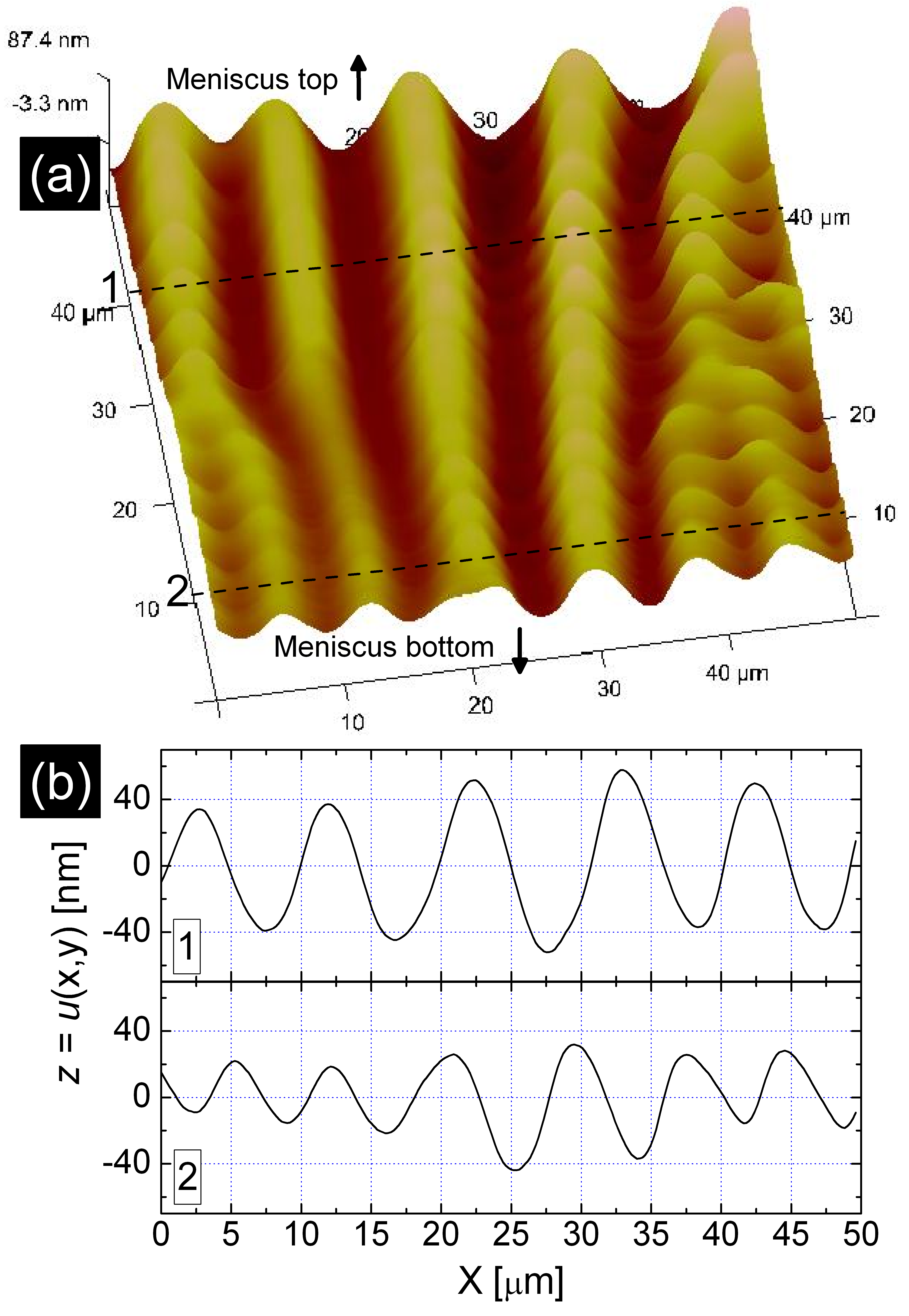
To confirm the results obtained through optical studies, we used AFM (Nanoscope Icon, Veeco, CA) to probe the meniscus structure. To our knowledge, we report here on the first AFM experiments performed on FSF. Those very delicate measurements were performed in air in the smC∗ phase with the microscope operated in both tapping and peak force modes using two different tips afm . Figure 4 exhibits the AFM results in the stripes region. The obtained image [Fig. 4(a)] and profiles [Fig. 4(b)] undoubtedly confirm the undulation of the smectic-air interface. Both the undulation amplitude (nm) and wavelength (m) decrease from the thick to the thin areas and are quite consistent with those inferred from PSI. Furthermore, we have checked that the stripe period deduced from the AFM profiles is equal to that derived from the in situ optical image recorded just before scanning the free surface. Note that the secondary undulations along the stripes in the AFM image do not represent actual interface undulations but originate from scanning artefacts.
A possible mechanism that accounts for wrinkles in smC∗ menisci may be derived from the one first proposed by Johnson and Saupe johnson77 . Assuming a constant layer number, smA layers tend to contract upon cooling into the smC∗ phase because of an increase of the tilt angle. This contraction may not freely take place in the meniscus because its boundaries are rigidly pinned to the solid substrate chevron . Therefore, a mechanical stress results and it is as if a negative pressure, or dilation, were applied to the meniscus at the phase transition. And it is well-known that dilation-induced strain in smectics can be relaxed by layer undulations in cases of strong anchoring johnson77 ; delaye73 ; clark73 ; rosenblatt77 ; oswpier . In our experiments, layers undulate at free surfaces and in the bulk of the film as well. These instabilities may very well explain the existence of director splay domains without invoking surface-induced spontaneous polarization, as proposed earlier meyer73 ; harth09 .
We can account for interfacial undulations by adding a surface tension term in the original model of Clark and Meyer clark73 . Close to , we may assume a very small tilt angle tiltac and therefore use the elastic free energy of a smA liquid crystal, as a first approximation. In terms of the layer displacement , in the -direction, and assuming small interfacial slopes, the simplest free energy density takes the form (in two dimensions)
| (1) | |||||
where is the film thickness, is the wave vector of the instability (in the -direction), and . The first integral in is the usual elastic contribution describing changes in layer thickness (described by the compression modulus ) and splay curvature (quantified by the splay elastic constant ). The second integral is the additional surface tension term ( is the smectic-air interfacial tension) which will quantify the surface energy cost associated with interfacial deformations. At the instability threshold, we may look for a solution of the form , where is the strain induced to the layers due to the change . Minimization of with the above form of leads to an equation for from which we get , where the symmetry and the condition were used. . Here, is not a mere constant, as in clark73 , because the layers are free to undulate at free surfaces. Injecting the final field in , the condition for instability, , is met for exceeding a threshold
| (2) |
with a dimensionless parameter given by . Because is a function of and , the critical wavevector and critical strain cannot be easily determined analytically but can be found numerically by minimizing . Taking N and gives m and we estimate picano00 ; veum06 . For a given , the value of is adjusted till Eq. (2) is satisfied for an appropriate range. For m, for example, this calculation predicts m and at threshold, corresponding to a critical displacement nm which is independent of film thickness, as in clark73 . The computed value of is of the same order of magnitude than the experimental one derived at threshold, m. Furthermore, our calculations show that increases with (more precisely, , results not shown), which is also consistent with the experimentally observed trend (Fig. 2). The dilation is greater in thicker parts of the meniscus because more layers are involved. Therefore, a dilation gradient occurs in the meniscus, suggesting that the 2D square lattice develops only when a high enough dilative strain has been reached. It is then very tempting to think that this lattice corresponds to the network of parabolic focal conics (PFC) defects mentioned in earlier studies picano00 ; oswpier ; rosenblatt77 ; delrieu74 . Indeed, PFC’s nucleate in (highly) dilated smA samples to (partly) relax the stress. This is precisely what seems to occur here in the meniscus.
Neither the stripes nor the 2D pattern appear in the flat film because no layer dilation occurs there at the phase transition, at least within our experimental conditions (i.e. for m). Indeed, if layers contract sufficiently below , it is well-known that smectic layers can sustain compression without undulating oswpier and we have checked this fact within our simple model (). Note, however, that Gorecka et al. gorecka95 observed instabilities in free standing smectic films but only for thick enough films (m).
Finally, in contrast to instabilities in sandwiched cells, the structures in smC∗ menisci are stable for weeks. We may expect the numerous dislocations in the meniscus to rearrange locally to relax the stress. Such plastic relaxation mechanisms are indeed very likely oswpier but fail to explain the long term stability of meniscus patterns.
To conclude, our results provide clear-cut evidences that the meniscus structure in smC∗ (smC) samples is more complex than that presumed earlier as it is characterized by undulations of the smectic layers. Additional experiments are currently in progress to investigate the influence of film thickness and the behavior of colloidal inclusions. On the theory side, a more sophisticated model involving thickness gradients and the coupling of -director distortions to layer undulations should be worked out.
The authors cordially acknowledge L. Lejček and B. Pouligny for very helpful discussions and thank J. P. Salvetat for suggesting the AFM experiments.
References
- (1) J.S. Rowlinson and B. Widom, Molecular Theory of Capillarity (Dover, New York, 2002).
- (2) P. Pieranski et al., Physica A 194, 364 (1993).
- (3) F. Picano, R. Holyst, and P. Oswald, Phys. Rev. E 62, 3747 (2000).
- (4) A. Poniewierski, P. Oswald, and R. Holyst, Langmuir 18, 1511 (2002).
- (5) P. Oswald and P. Pieranski, Smectic and Columnar Liquid Crystals (Taylor & Francis, Boca Raton, 2005).
- (6) T. Stoebe, P. Mach, and C. C. Huang, Phys. Rev. Lett. 73, 1384 (1994).
- (7) P. A. Kralchevsky and K. Nagayam, Adv. Coll. Inter. Sci. 85, 145 (2000).
- (8) J. C. Loudet, A. M. Alsayed, J. Zhang, and A. G. Yodh, Phys. Rev. Lett. 94, 018301 (2005).
- (9) M. Oettel and S. Dietrich, Langmuir 24, 1425 (2008).
- (10) P. Poulin, H. Stark, T. C. Lubensky, and D. A. Weitz, Science 275, 1770 (1997).
- (11) T. C. Lubensky, D. Pettey, N. Currier, and H. Stark, Phys. Rev. E 57, 610 (1998).
- (12) P. V. Dolganov and P. Cluzeau, Phys. Rev. E 78, 021701 (2008).
- (13) C. Bohley and R. Stannarius, Soft Matter 4, 683 (2008).
- (14) P. G. de Gennes and J. Prost, The Physics of Liquid Crystals (Clarendon Press, Oxford, 1993).
- (15) R. B. Meyer and P. S. Pershan, Solid State Commun. 13, 989 (1973).
- (16) M. Conradi, P. Ziherl, A. Šarlah, and I. Muševič, Eur. Phys. J. E 20, 231 (2006).
- (17) K. Harth and R. Stannarius, Eur. Phys. J. E 28, 265 (2009).
- (18) J. Huang et al., Science 317, 650 (2007).
- (19) H. Vandeparre et al., Soft Matter 6, 5751 (2010).
- (20) D. P. Holmes and A. J. Crosby, Phys. Rev. Lett. 105, 038303 (2010).
- (21) J. R. Lalanne et al., Phys. Rev. A 44, 6632 (1991).
- (22) Note that this 2D pattern is actually visible in figs. 4 and 6 of ref. harth09 but is not mentionned nor discussed in the text.
- (23) J. C. Loudet, A. G. Yodh, and B. Pouligny, Phys. Rev. Lett. 97, 018304 (2006).
- (24) A. Harasaki, J. Schmitt, and J. C. Wyant, Appl. Opt. 39, 2107 (2000).
- (25) D. W. Robinson and G. T. Reid, Interferogram Analysis (Institute of Physics Publishing, Bristol, 1993).
- (26) In the tapping mode, phase images were obtained using a silicon tip (stiffness N/m, tip radius nm, kHz) whereas tips (stiffness N/m, tip radius nm) were used for imaging in the peak force mode.
- (27) D. Johnson and A. Saupe, Phys. Rev. A 15, 2079 (1977).
- (28) This is somewhat analogous to the chevron instability encountered in ferroelectric smectics. See T. P. Rieker et al., Phys. Rev. Lett. 59, 2658 (1987) and P. Cluzeau et al., Eur. Phys. J. B 3, 73 (1998).
- (29) M. Delaye, R. Ribotta, and G. Durand, Phys. Lett. 44A, 139 (1973).
- (30) N. A. Clark and R. B. Meyer, Appl. Phys. Lett. 22, 493 (1973).
- (31) C. S. Rosenblatt, R. Pindak, N. A. Clark, and R. B. Meyer, Journal de Physique 38, 1105 (1977).
- (32) This is true only if the smA-smC phase transition is of second order.
- (33) J. M. Delrieu, J. Chem. Phys. 60, 1081 (1974).
- (34) M. Veum et al., Phys. Rev. E 74, 011703 (2006).
- (35) E. Gorecka, M. Glogarová, L. Lejček, and H. Sverenyák, Phys. Rev. Lett. 75, 4047 (1995).