Driving rotational transitions in molecules on a chip
pacs:
37.10.Pq, 33.20.Bx, 33.57.+c, 37.20.+j, 42.15.Dp, 42.50.MdAbstract
Polar molecules in selected quantum states can be guided, decelerated and trapped using electric fields created by microstructured electrodes on a chip. Here we explore how transitions between two of these quantum states can be induced while the molecules are on the chip. We use CO () molecules, prepared in the rotational level, and induce the rotational transition with narrow-band sub-THz (mm-wave) radiation. First, the mm-wave source is characterized using CO molecules in a freely propagating molecular beam, and both Rabi cycling and rapid adiabatic passage are examined. Then, we demonstrate that the mm-wave radiation can be coupled to CO molecules that are less than 50 above the chip. Finally, CO molecules are guided in the level to the center of the chip where they are pumped to the level, recaptured, and guided off the chip.
I Introduction
The manipulation of polar molecules above a chip using electric fields produced by microstructured electrodes on the chip surface is a fascinating new research field Meek:2009p1699 ; Meek:2009p012063 . Miniaturization of electric field structures enables the creation of large field gradients, i.e. large forces and tight potential wells for polar molecules. Above a chip, the positions of these potential wells, and thereby the positions of the trapped molecules, can be controlled to an extreme precision. In addition, present-day microelectronics technology makes it possible to integrate multiple tools and devices onto a compact surface area. These can include lenses, decelerators and traps for polar molecules but also integrated detection elements like radiation sources and optical cavities, for instance. Over a decade ago, similar notions launched the field of atom chipsWeinstein:1995p4004 ; Hinds:1999pR119 ; Fortagh:2007p235 , in which atoms are manipulated and controlled above a chip using magnetic fields produced by current-carrying wires. Whereas atom chips have been used to demonstrate rapid Bose-Einstein condensationHaensel:2001p498 and have already found applications in matter-wave interferometrySchumm:2005p57 and in inertial and gravitational field sensingZoest:2010p1540 , molecule chips are still in their infancy and their potential still needs to be explored.
A particular advantage of using molecules instead of atoms on a chip is that they can be coupled to photons over a wider range of frequencies. The fundamental molecular vibrational modes can be addressed with mid-infrared photons whereas their overtones and combination modes extend into the near-infrared range. In addition, polar molecules have a dense spectrum of rotational transitions in the sub-THz, or mm-wave, region of the spectrum. During the last years, several schemes have been proposed for quantum computation in which trapped polar molecules in selected quantum states serve as qubits.Andre:2006p636 ; Demille:2002p067901 In these schemes, flipping of a qubit can be accomplished by inducing a transition to another internal quantum state in the molecule, provided the molecule remains trapped in the final state as well. Transitions between rotational levels within a given electronic and vibrational state are especially well suited for this; pairs of rotational levels that can be trapped in external fields and that are connected via electric dipole allowed transitions can be found. Transitions between these rotational levels can be driven with unit efficiency and yet the lifetimes of the rotationally excited levels are very long; vibrational and electronic transitions, in contrast, often result in leakage of population out of the system of coupled states. Moreover, the required narrow-band, coherent radiation sources spanning the microwave to sub-THz frequency range can be integrated on a microchip and no adverse effect of the microwave radiation on the performance of the chip components is expected.
In the experiments reported here we explore the use of rotational transitions in molecules on a chip. The system we use is the carbon monoxide molecule, prepared with a pulsed laser in a single rotational level () of its first electronically excited, metastable state (). The rotational transition is induced using a continuous wave source of radiation with a wavelength of around 1.5 mm. Molecules in the rotationally excited level are subsequently state-selectively detected using ionization with another pulsed laser system.
The paper consists of two parts. In the first part, the experimental set-up is described and the mm-wave source as well as the rotational excitation step are characterized using experiments on CO molecules in a freely propagating molecular beam. These experiments demonstrate that efficient and robust rotational excitation can be achieved when the molecules pass through the focused mm-wave beam at the appropriate position, such as to fulfill the conditions for rapid adiabatic passage. In the second part, experiments are described in which the mm-wave radiation interacts with the metastable CO molecules while these are propagating with a constant velocity at a close distance above the chip. These experiments explicitly demonstrate that the mm-wave radiation can be coupled onto the chip and that the CO molecules — guided in moving electric field traps to the center of the chip while in the level — can be pumped to the level while on the chip. The rotationally excited molecules can subsequently be re-captured in the miniaturized electric field traps, transported to the end of the chip and detected.
II Rotational excitation of metastable CO in a beam
To characterize the mm-wave source and the rotational excitation scheme in metastable CO, we first performed experiments using the setup that is schematically depicted in Figure 1. A mixture of 20% CO in Krypton is expanded into vacuum from a pulsed valve (General Valve; series 99) operating at a repetition rate of 10 Hz. Before passing through the first skimmer, the CO molecules are excited from the rotational level in the electronic and vibrational ground-state () to the upper -doublet component of the level. This particular level has a radiative lifetime of 2.6 ms.Gilijamse:2007p1477 Alternatively, the ground state molecules can be excited from the level to the upper -doublet component of the level. The 206 nm radiation from the pulsed excitation laser (1 mJ in a 5 ns pulse with a bandwidth of about 150 MHz) is weakly focused onto the molecular beam. In this way, an approximately 1 mm3 packet containing about 108 metastable CO molecules is obtained after the skimmer. With the pulsed valve at room temperature, the mean velocity of the CO molecules is around 470 m/s and the velocity spread is rather large, with a full width at half maximum of 80 m/s.
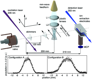
To better collimate the molecular beam, the CO molecules pass through a second 1 mm diameter skimmer on their way to the interaction region with the mm-wave radiation. The mm-waves are produced outside of vacuum. A microwave synthesizer (Agilent, model HP83623B with option 008; 1 Hz resolution) drives an “Armadillo” millimeter-wave source module (Agilent, model 83558A, 75–110 GHz, 0 dBm output) which in turn pumps a millimeter-wave power amplifier (Spacek Labs Inc., model SPW-18-14; 75–110 GHz, +10 dB). The output of this W-band amplifier is then frequency doubled with a passive multiplier (Virginia Diodes Inc., models VDI-WR5.1x2; 150–220 GHz), losing roughly 12 dB and resulting in a mm-wave beam of roughly 2 dBm or 0.6 mW at 200 GHz. A standard gain horn from Millitech (model SGH-05-RC000) is used to launch the mm-wave beam into free space.Duffy:2005p093104 While the use of a corrugated scalar feedhorn would have ensured a pure Gaussian beam profile, it is evident from the measured profiles in Figure 1 that the presence of side-lobes is within the noise level of the experiment. The mm-wave beam waist at the exit of the horn is then expanded and transfered to the molecular beam with a pair of plastic lenses (L1 Teflon, L2 TPX) configured in a Gaussian beam telescope geometry.Goldsmith:1982p227 The lenses’ focal lengths are 6 and 15 cm, respectively. The mm-wave beam is introduced into the vacuum chamber through a Teflon window and intersects the molecular beam under right angles. In this experiment, the Armadillo is oriented so that the polarization of the mm-waves is parallel to the molecular beam axis and is set to drive the transition in the state CO. Since the Earth’s magnetic field induces Zeeman splittings of the rotational levels, an offset magnetic field of about 200 Gauss is applied to define the main direction of the magnetic field to be perpendicular to the polarization of the mm-radiation. In this configuration, the selection rules for the various -components of the rotational transition are .
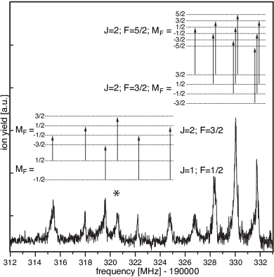
Downstream from the mm-wave interaction zone, the metastable CO molecules can be state-selectively detected. Carbon monoxide molecules in the state can be resonantly excited to selected rotational levels of the state, from which they can be ionized by another photon from the same laser pulse. A tunable pulsed laser (4 mJ energy in a 5 ns pulse with a bandwidth of 0.2) operating around 283 nm is used for this (1+1) resonance enhanced multi-photon ionization (REMPI) detection scheme. The ionization laser beam intersects the molecular beam perpendicularly and is only weakly focused with a diameter of about 1 mm. The resulting parent ions are mass-selectively detected in a compact linear time-of-flight (TOF) mass-spectrometer equipped with a micro-channel plate (MCP) detector. Ionization is performed with the voltages on the ion extraction electrodes switched off in order to avoid parity-mixing of the -doublet components in the metastable state. A scheme of the energy levels involved in the preparation of the metastable molecules, in the mm-wave excitation and in the subsequent (1+1)-REMPI detection is shown in Figure 2. In this Figure, the measured (1+1)-REMPI spectra from the upper -doublet components of the and levels are shown as well.
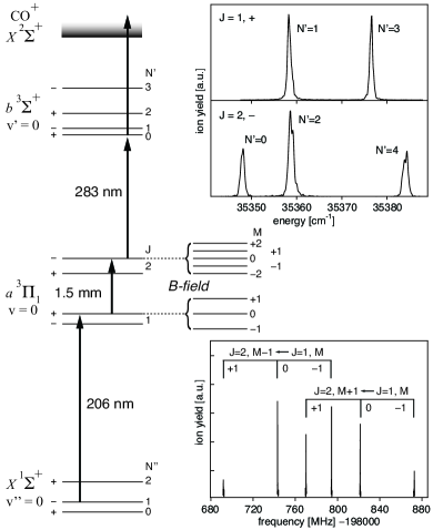
If the metastable CO molecules are prepared in the level while the level is probed by (1+1)-REMPI, a mm-wave spectrum of the transition can be recorded against zero background. Such a spectrum, measured with approximately 20 W/cm2 of mm-wave radiation, is shown in Figure 2 as well. Three and three transitions are observed. The observed width of the individual transitions of about 50 kHz is attributed to the limited interaction time of the CO molecules with the mm-wave radiation (a few tens of microseconds) in combination with the slight inhomogeneity of the applied magnetic field.
II.1 Characterizing the mm-wave beam
The combination of the laser preparation of metastable CO at a well-defined time and position with state-selective detection at a known delay and distance further downstream enables us to selectively monitor molecules within a narrow velocity interval. The doubly-skimmed molecular beam has a full width at half maximum transverse spread of approximately 4 mm in the ionization detection region. With the experimental geometry as shown in Figure 1, only metastable CO molecules in a 1 mm diameter and 4 mm long cylinder, oriented with its long axis perpendicular to the molecular beam and perpendicular to the propagation direction of the mm-wave radiation, are detected. In the mm-wave excitation zone, the length of the cylindrical volume of the metastable CO molecules that will be probed further downstream is only 2.5 mm. This experimental setup enables an accurate in situ characterization of the spatial profile of the mm-wave radiation. For this, metastable CO molecules are prepared in the level and probed from the level. The mm-wave radiation, polarized parallel to the external magnetic field in this case, is kept fixed to the center frequency of the transition at 198782.250 MHz. The preparation and detection laser are timed such that only molecules with a velocity of 4701 m/s are detected. The mm-wave radiation is only switched on during a 2 time interval. By measuring the (1+1)-REMPI signal from the level as a function of the time delay between laser preparation and the center of the 2 interval, the spatial profile of the mm-wave radiation is sampled. The result of such scans is shown in the lower part of Figure 1, for two different positions of the beam waist; the measured (dots) spatial profile is shown when the waist of the mm-wave beam is close to the axis of the molecular beam (Configuration A) and when the waist is moved closer to the mm-wave source, i.e., when the molecules cross a divergent mm-beam (Configuration B).
For a Gaussian beam with peak amplitude and waist size , the complex electric field amplitude is given by
| (1) |
where is the radial distance from the axis of the beam, is the axial distance from the waist, is the radius at which the electric field amplitude drops to of its value on axis, is the radius of curvature of the beam’s wavefronts and is the wavelength. The solid curves in panel A and B of Figure 1, are fits to the calculated excitation probability to the level (vide infra) using this expression for the electric field distribution. From this fit, we extract a value of = 5 mm for the beam waist radius.
II.2 Rabi oscillations and rapid adiabatic passage
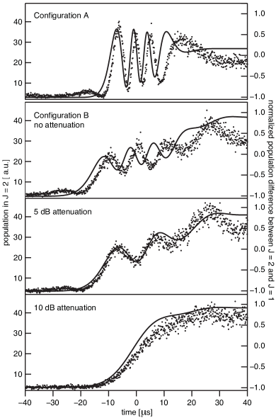
If the mm-wave radiation is tuned to the frequency of an allowed transition, the metastable CO molecules undergo Rabi oscillations between the two coupled levels while they fly through the mm-beam.Rabi:1937p652 ; Ramsey ; Cohen-Tannoudji Abruptly turning off the mm-wave source while the molecules are still in the interaction region interrupts the Rabi cycling. The CO molecules will fly on and when they arrive in the ionization detection region they still have the population distribution of the moment when the mm-wave is switched off. This enables us to directly monitor the population distribution as a function of time, thereby visualizing the Rabi oscillations. The top panel of Figure 3 shows the measured population in the level as a function of the switch-off time of the mm-wave source, which is tuned to the center frequency of the transition with an intensity of about 0.2 mW/cm2. In these measurements the molecules pass close to the waist of the mm-wave beam (Configuration A in Figure 1); time zero is defined as the moment when the molecules are in the center of the mm-wave beam.
To describe the evolution of the two level system, and , in the presence of a light field , we use the representation suggested by Feynman et al..Feynman:1957p49 The wave function of a molecule is
| (2) |
and the energies of the two eigenstates are and . We define a so-called population vector (, , ) = (, , ), a field vector (, , ) = (, , ), where is the dipole moment of the transition, 0.61 Debye in this specific caseMeek:2010phd , and . Then the time evolution of the system is described by the equation
| (3) |
The first two components of are the real and imaginary part of the coherence between the amplitudes in the two levels, whereas is the population difference between the upper and the lower level. The first component of is the angular Rabi frequency at resonance and the third component is the detuning from resonance. Equation (3) states that the population vector precesses around the field vector . For instance, when the radiation field is on resonance and the initial population is in the level (), equation (3) dictates an evolution of the population vector as , as expected for Rabi oscillations. If the frequency nor the intensity of the electric field changes over time, the probability to be in the rotationally excited level is
| (4) |
It is evident that by abruptly interrupting the resonant () Rabi cycling at , it is possible to transfer the whole population from one state to the other. However, this is not a very robust method, mainly because depends on the electric field strength, so any variation of the field strength requires a correction of the switch-off time. Moreover, molecules interacting with different parts of the mm-wave beam experience different field strengths and therefore cycle with different frequencies. This effect can actually be seen in the experimental data shown in the top panel of Figure 3: the amplitude of the oscillations progressively decreases, as molecules flying through regions with different electric field strengths accumulate different phases. The solid curve shown in this panel is a simulation (not a fit) computed using the formalism described here with only experimentally determined variables for input. The waist of the mm-wave beam and the distance from the waist where the molecules pass through are extracted from the fit of the spatial profiles shown in Figure 1, in which the expression for at = 2 has been used.
To efficiently transfer population between two levels in a more robust way, rapid adiabatic passage can be used.Treacy:1968p421 The fundamental idea behind rapid adiabatic passage is to have a small angle between the field vector and the population vector ; since precesses around the population will follow the field vector when this one is made to evolve slowly to the desired orientation. The degree of control over the population transfer is limited by the angular extent of the precession cone. When the initial population is in the level, i.e. , the field vector can be made almost parallel to the population vector by choosing a detuning that is much larger than the Rabi frequency. Then, by sweeping the radiation frequency through the resonance until the detuning is again much larger than the Rabi frequency but with inverted sign, all the population is transferred to the level. The direction of the frequency sweep is irrelevant for the population transfer. The condition for the process to be adiabatic is that the rate of change in the direction of is smaller than the precession frequency, which is proportional to .Wichman:1990p358
In our experiments, the frequency sweep required for the rapid adiabatic passage results from the Doppler shift that occurs when the metastable CO molecules pass through the curved wavefronts of the divergent part of the Gaussian mm-wave beam. This Doppler shift, , is the time derivative of the phase of the electric field as seen by the molecules. Since the molecules fly along the -axis with a velocity , the Doppler shift is , or, from Equation (1),
| (5) |
The condition that the initial and final detuning must be much larger than the Rabi frequency is automatically fulfilled when the molecules pass through the divergent part of the Gaussian beam as they experience a Gaussian time dependence of the electric field strength together with a linear frequency chirp111Note that if the distance between the molecular beam axis and the mm-beam axis is , the molecules experience a field amplitude reduced by a constant factor , but that the overall Gaussian time dependence and the Doppler shift do not depend on . In the experiments, we did not optimize the -position, although we expect to have been close to the position based on the relative widths and amplitudes of the data shown in Figure 1; in any case, the -offset remained constant throughout the experiments..
In the lower three panels of Figure 3, the measured population in the level is shown (dots) as a function of switch-off time of the mm-wave radiation when the molecules pass through the divergent part of the mm-wave beam, about 4 cm away from the beam waist (Configuration B in Figure 1). In going from the second panel to the third panel, the power of the mm-waves is decreased by about a factor three while in the lowest panel the power is a factor ten below the one in the second panel. This reduction in mm-wave power results in an increase of the ratio of the frequency chirp to the Rabi frequency, and thus into a rapid adiabatic passage with ever fewer oscillations. By numerically solving Equation (3), using the two fitted parameters of the mm-wave beam and the known experimental geometry as input, the simulated curves (solid) are obtained. On the axis on the right, the third component of the population vector, , is shown from which it is seen that robust and near-complete transfer of population to the final level is obtained in this rapid adiabatic passage scheme.
III Experiments on the molecule chip
The experimental setup that is used to interrogate CO molecules on the chip with mm-wave radiation is shown in Figure 4. The chip used for these experiments is a new, longer version of the chip that was previously described by our group.Meek:2009p1699 ; Meek:2008p153003 ; Meek:2009p055024 It consists of an array of 1848 equidistant gold electrodes, each of which is 4 mm long, 10 wide and approximately 100 nm high. They are deposited onto a 1 mm thick glass substrate with a 40 center-to-center spacing, forming a structure that is 74 mm long (Micro Resist Technology GmbH). When appropriate potentials are applied to the electrodes, tubular electric field geometries of 4 mm length and 20 diameter are generated, on the axis of which the electric field strength drops to zero. These electric field geometries, centered roughly 25 above the chip surface, act as traps for molecules in low-field-seeking quantum states. Two traps are formed for each 6 electrodes on the chip surface, i.e., the traps are spaced 120 apart. For metastable CO molecules in the low-field-seeking components of the and levels, these traps have a depth of 65 mK and 30 mK, respectively. When sinusoidal waveforms are applied to the electrodes, the traps translate over the chip at a constant height and without changing their shape. The speed of the motion of the trap is directly proportional to the frequency of the waveform. When the frequency of the waveform is constant the traps move at constant velocity and the device acts as a guide. If the frequency of the waveforms is chirped down, the traps slow down and the chip can be used as a decelerator for low-field-seeking polar molecules. For more details on the guiding, deceleration and trapping of metastable CO molecules on the chip, the reader is referred to the existing literature (see, in particular, ref.Meek:2009p055024 ). In the present study the molecule chip has only been used as a supersonic molecular conveyor belt, guiding the metastable CO molecules over the chip at a constant velocity.
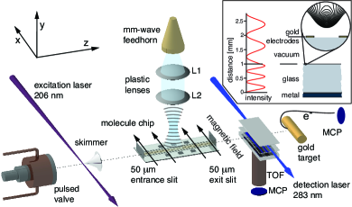
It is not a priori obvious that the mm-wave radiation can be coupled to the molecules on the chip, as these move only at a distance of about 1/60 of the wavelength above the plane of the metallic electrodes. As indicated in Figure 4, the mm-waves are coupled onto the molecule chip perpendicular to its surface. To avoid reflection of the radiation from the microstructured electrodes, the polarization of the mm-waves has to be perpendicular to the electrodes, i.e., parallel to the molecular beam axis. The mm-waves are then largely transmitted through the electrodes, travel through the glass substrate (refractive index about 2)Lamb:1996p1997 , and reflect from the steel plate on which the glass chip is mounted. As schematically shown in the inset of Figure 4, the stationary electric field intensity of the mm-wave radiation is expected to be about 75% of its maximum value at the location of the molecules.
To explicitly demonstrate that the mm-wave radiation can be coupled onto the chip and that rotational transitions can be induced in molecules at close distance above the chip surface, we measured the rotational transition in CO molecules above a chip. We used 13CO molecules for these measurements because, as will be shown later, these can be guided more efficiently on the chip; the nuclear spin of the 13C atom and the resulting hyperfine splitting of the rotational levels in 13CO prevents losses due to non-adiabatic transitions in this isotopologue.Meek:2009p1699 An external magnetic field of 10 Gauss, perpendicular to the polarization direction of the mm-wave radiation, is applied and the -resolved rotational spectrum is recorded by detecting the molecules in the level further downstream via (1+1)-REMPI. Although no voltages are applied to the chip electrodes for these measurements, the 50 high entrance and exit slits ensure that only molecules within 50 from the surface of the chip can contribute to the observed signal. The spectrum is shown and assigned in Figure 5. The width of the individual -components of 400–500 kHz is attributed to inhomogeneities of the magnetic field above the chip, induced by the metal components of the chip-holder. It is important to realize that the rotational transition can only be observed when the electric field of the chip is off; when the electric fields are present above the chip while guiding or decelerating molecules, the Stark broadening of each transition is many GHz, bringing the vast majority of molecules out of resonance with the narrow band mm-wave radiation.
III.1 Spectroscopic identification of CO molecules
In previous experiments in which we guided and decelerated metastable CO molecules on a chip, we observed a background signal from CO molecules that were rather insensitive to the electric fields above the chip.Meek:2008p153003 ; Meek:2009p055024 We tentatively attributed this background signal to metastable CO molecules in the non-Stark-shifted -levels of the upper -doublet component of . With the mm-wave radiation we can now spectroscopically test whether this assignment is correct. For this, we irradiate the molecules on the chip with mm-waves that are resonant with a rotational transition from these -levels to a low-field-seeking component of the level. Molecules in this low-field-seeking state will be deflected upwards by the exponentially decaying electric field above the chip, and will no longer pass through the 50 high exit slit at the end of the chip. Any molecule undergoing this transition whose velocity does not match the trap velocity cannot be captured by the traveling field minima or stably guided to the end of the chip. If our previous assignment is correct, therefore, resonant mm-wave excitation will result in a depletion of the background signal.
For these experiments, the General valve is cooled to 140 K to reduce the mean velocity of the CO beam to 300 m/s; the presently available electronics do not allow guiding of the molecules on the chip at much higher speeds than this. The mm-source is resonant with the , , , , transition in 13CO (indicated with an asterisk in Figure 5), promoting molecules from a non-Stark-shifted level into a low-field-seeking one. Instead of state-selective detection of the metastable CO molecules via (1+1)-REMPI, the full velocity distribution of the beam of metastable CO molecules — independent of the rotational state that they are in — is monitored by time-resolved detection of the Auger electrons that are generated upon impact of these molecules on a gold surface.Meek:2009p055024 Measurements of the arrival time distribution of the 13CO molecules are shown in the upper part of Figure 6, both without (black curve) and with (red curve) the mm-wave radiation present; the difference between these measurements, showing the depletion in the background signal, is shown as well (blue curve). The main peak in the signal, observed at 1140 , results from CO molecules that are stably guided over the chip in traps that move with a velocity of 300 m/s; from this the distance from the laser excitation point to the Auger detector can be precisely determined as 342 mm. The abrupt cut-off in signal around 930 reflects the abrupt switching on of the voltages on the molecule chip; the signal at earlier times results from fast CO molecules that had already left the chip when voltages were applied and that are therefore unaffected. Most of the CO molecules in low-field-seeking states that are on the chip when the voltages are applied are deflected upwards and will thus no longer make it to through the 50 exit slit to the detector, thereby explaining the abrupt signal decrease. It is clear from the measurement, however, that there is a prominent background signal remaining, and that this background signal can indeed be partially depleted with the mm-waves. The depletion is expected to be at most half of the background signal since the CO molecules are distributed over two levels (, , ) in the magnetic field, whereas only one of these is addressed by the mm-waves. The experimentally observed depletion is about 20%, indicating that the population transfer to the level does not happen with unit efficiency. This could be explained by a mismatch between the Rabi period and the interaction time or a mismatch between the width of the mm-wave sectrum and the width of the absorption line. Moreover, some rotationally excited molecules might not be deflected strongly enough and might still make it through the exit slit. The latter will certainly hold for those rotationally excited molecules that are already close to the exit of the chip when the electric fields are switched on.
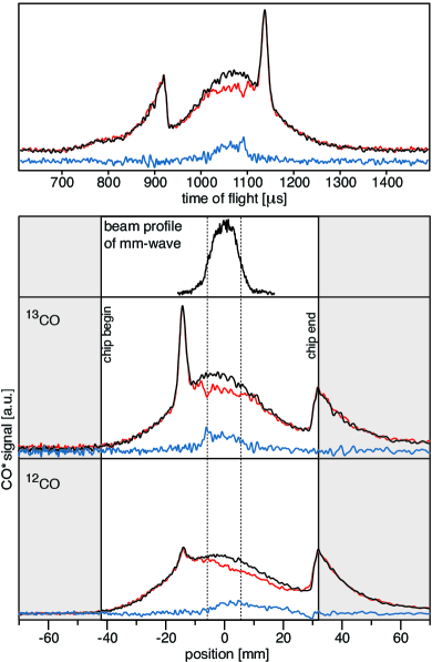
To aid in the interpretation of the measured arrival time distributions, the time scale can be converted to a position scale, showing where the CO molecules that contribute to a particular signal were located at the time that the voltages on the chip were switched on. These spatial distributions are shown in the lower part of Figure 6, together with the profile of the mm-wave beam on the chip; the zero of the position scale is arbitrarily taken at the center of the mm-wave beam. Only molecules that are in, or have already passed, the mm-wave beam before the voltages on the chip are switched on can be rotationally excited; when the electric fields on the chip are on, the rotational transitions are Stark-broadened too much. A clear depletion of the background signal is indeed only observed for those molecules that interacted with the mm-waves prior to switching on the electric fields.
In the lower part of Figure 6 similar measurements are shown for 12CO, spectroscopically identifying the metastable CO molecules that contribute to the background signal as molecules in levels. The large difference in the efficiency of guiding either 13CO or 12CO on the chip, is evident from these measurements.
III.2 Population transfer between trapped levels
In the tubular electric field traps above the chip, low-field-seeking CO molecules are exposed to electric field strengths that range from zero up to several kV/cm. As the molecules sample a large fraction of these field strengths on a time-scale and as the Stark shifts in the most strongly confined -components of the and level are sufficiently different, the traps must be temporarily turned off to induce a rotational transition between these levels. After this, the traps can be turned on again and the CO molecules can be recaptured. For the overall efficiency of this scheme, the motion of the molecules relative to the center of the moving trap is important. In our experiment, the molecules have a velocity spread inside the trap of a few m/s, limiting the maximum time during which the trap can be switched off to several . From the experiments in the free beam it is seen, however, that near-complete population transfer between the rotational levels in CO can be achieved by Rabi flopping in less than 3 ; guiding, releasing, transferring population and re-catching the molecules thus seems possible.
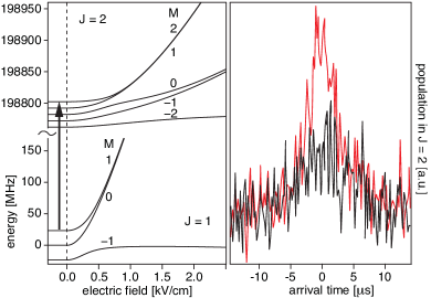
The arrival time distributions of metastable CO molecules subjected to such a procedure are shown in Figure 7. The 12CO molecules are prepared in the level and guided to the center of the chip in traps that move at a speed of 300 m/s. When the molecules arrive near the center of the chip, the electric fields are switched off and the mm-wave source drives the , , transition, as schematically indicated in the panel on the left. During this time, the molecules continue to move in the -direction with a mean speed of 300 m/s, but they are no longer confined, and some of them are therefore not recaptured when the trapping voltage is turned on again 4 later. Those molecules that are re-captured are guided to the end of the chip and fly into the ionization detection region. The red curve in Figure 7 shows the yield of molecules in the level, after interaction with the mm-wave field, as a function of time; the zero on the time axis is when molecules with a velocity of 300 m/s should arrive. The black curve shows the result when the mm-wave radiation is off; this background signal results from molecules that are non-resonantly ionized by the laser that is tuned to probe the level via the level in the -state.
IV Conclusion
The combination of (i) laser preparation of molecules in a single rotational level at a well-defined time and position, (ii) tunable narrow-band mm-wave radiation that can transfer the population to another rotational level at a known distance downstream, and (iii) state-selective detection of the molecules at a known delay and at a known position, yields unique possibilities. It has been used here for a detailed in situ characterization of the mm-wave beam, which is non-trivial otherwise at these wavelengths. Moreover, we have used it to experimentally record the time-dependence of the population transfer in a true two-level system, not only in the case of Rabi-cycling but also under conditions where rapid adiabatic passage occurs; the measurements shown in Figure 3 are a text-book example for these processes. The freely propagating mm-wave beam produced by the Armadillo can be conveniently coupled to the molecules on the chip. We have used this to spectroscopically verify that the background signal observed in earlier experiments on guiding CO molecules on a chip originates from molecules in levels, as anticipated. Last but not least, CO molecules in the level have been guided on the chip and have then been rotationally excited with the mm-wave radiation to the level, in which they have been recaptured on the chip.
Characterizing the electric field of the mm-wave beam above the chip is more challenging than for the free beam, in particular because of the magnetic field inhomogeneity at the surface of the chip. More generally, whenever a high spectroscopic resolution is required in the experiment, this inhomogeneity has to be minimized. The reflection of the mm-waves from the holder of the chip as well as from the electrodes has to be considered in the design phase of the next generation of microchips.
V Acknowledgment
This work has been funded by the European Community’s Seventh Framework Program FP7/2007-2013 under grant agreement 216 774, and ERC-2009-AdG under grant agreement 247142-MolChip. We acknowledge fruitful discussion with Boris Sartakov. G.S. gratefully acknowledges the support of the Alexander von Humboldt-Stiftung.
References
- (1) S. A. Meek, G. Santambrogio, H. Conrad, and G. Meijer, J. Phys.: Conf. Ser. 194 (2009), 012063.
- (2) S. A. Meek, H. Conrad, and G. Meijer, Science 324 (2009), 1699.
- (3) E. A. Hinds and I. G. Hughes, J. Phys. D: Appl. Phys. 32 (1999), R119.
- (4) J. Fortàgh and C. Zimmermann, Rev. Mod. Phys. 79 (2007), 235.
- (5) J. D. Weinstein and K. G. Libbrecht, Phys. Rev. A 52 (1995), 4004.
- (6) W. Hänsel, P. Hommelhoff, T. W. Hänsch, and J. Reichel, Nature 413 (2001), 498.
- (7) T. Schumm, S. Hofferberth, L. M. Andersson, S. Wildermuth, S. Groth, I. Bar-Joseph, J. Schmiedmayer, and P. Krüger, Nat. Physics 1 (2005), 57.
- (8) T. van Zoest, N. Gaaloul, Y. Singh, H. Ahlers, W. Herr, S. T. Seidel, W. Ertmer, E. Rasel M. Eckart, E. Kajari, S. Arnold, G. Nandi, W. P. Schleich, R. Walser, A. Vogel, K. Sengstock, K. Bongs, W. Lewoczko-Adamczyk, M. Schiemangk, T. Schuldt, A. Peters, T. Koönemann, H. Müntinga, C. Lämmerzahl, H. Dittus, T. Steinmetz, T. W. Hänsch, and J. Reichel, Science (2010), 1540.
- (9) A. André, D. DeMille, J. M. Doyle, M. D. Lukin, S. E. Maxwell, P. Rabl, R. J. Schoelkopf, and P. Zoller, Nat. Physics 2 (2006), 636.
- (10) D. DeMille, Phys. Rev. Lett. 88 (2002), 067901.
- (11) J. J. Gilijamse, S. Hoekstra, S. A. Meek, M. Metsälä S. Y. T. van de Meerakker, G. Meijer, and G. C. Groenenboom, J. Chem. Phys. 127 (2007), 221102.
- (12) L. M. Duffy, Rev. Sci. Instr. 76 (2005), 093104.
- (13) P. F. Goldsmith, Infrared and millimeter waves, edited by k. j. button, vol. 6, ch. 5, p. 227, Academic, Orlando, 1982.
- (14) I. I. Rabi, Phys. Rep. 51 (1937), 652.
- (15) N. F. Ramsey, Molecular beams, Clarendon Press, Oxford, 1956.
- (16) C. Cohen-Tannoudji, B. Diu, and F. Laloë, Quantum mechanics, Wiley, New York, 1977.
- (17) R. P. Feynman, F. L. Vernon, and R. W. Hellwarth, J. Appl. Phys. 28 (1957), 49.
- (18) S. A. Meek, A stark decelerator on a chip, Ph.D. thesis, Freie Universität Berlin, 2010.
- (19) E. B. Treacy, Phys. Lett. A 27 (1968), 421.
- (20) B. Wichman, C. Liedenbaum, and J. Reuss, Appl. Phys. B 51 (1990), 358.
- (21) S. A. Meek, H. L. Bethlem, H. Conrad, and G. Meijer, Phys. Rev. Lett. 100 (2008), 153003.
- (22) S. A Meek, H. Conrad, and G. Meijer, New J. Phys. 11 (2009), 055024.
- (23) J. W. Lamb, Int. J. Infrared and Millimeter Wave 17 (1996), 1996.