Bonding, antibonding and tunable optical forces in asymmetric membranes
Abstract
We demonstrate that tunable attractive (bonding) and repulsive (anti-bonding) forces can arise in highly asymmetric structures coupled to external radiation, a consequence of the bonding/anti-bonding level repulsion of guided-wave resonances that was first predicted in symmetric systems. Our focus is a geometry consisting of a photonic-crystal (holey) membrane suspended above an unpatterned layered substrate, supporting planar waveguide modes that can couple via the periodic modulation of the holey membrane. Asymmetric geometries have a clear advantage in ease of fabrication and experimental characterization compared to symmetric double-membrane structures. We show that the asymmetry can also lead to unusual behavior in the force magnitudes of a bonding/antibonding pair as the membrane separation changes, including nonmonotonic dependences on the separation. We propose a computational method that obtains the entire force spectrum via a single time-domain simulation, by Fourier-transforming the response to a short pulse and thereby obtaining the frequency-dependent stress tensor. We point out that by operating with two, instead of a single frequency, these evanescent forces can be exploited to tune the spring constant of the membrane without changing its equilibrium separation.
1Department of Mathematics, Massachusetts Institute of Technology, Cambridge, MA 02139 \address2School of Engineering and Applied Sciences, Harvard University, Cambridge, MA 02138 \address3Department of Physics, Massachusetts Institute of Technology, Cambridge, MA 02139
(190.2620) Nonlinear optics: frequency conversion; (230.4320) Nonlinear optical devices
References
- [1] A. Ashkin, “Applications of laser radiation pressure,” Science 210(4474), 1081–1088 (1980).
- [2] J. D. Jackson, Classical Electrodynamics, 3rd ed. (Wiley, New York, 1998).
- [3] D. G. Grier, “A revolution in optical manipulation,” Nature 424, 810–816 (2003).
- [4] G. S. Wiederhecker, L. Chen, A. Gondarenko, and M. Lipson, “Controlling photonic structures using optical forces,” Nature 462(7273), 633–636 (2009).
- [5] M. L. Povinelli, M. Loncar, M. Ibanescu, E. J. Smythe, S. G. Johnson, F. Capasso, and J. D. Joannopoulos, “Evanescent-wave bonding between optical waveguides,” Opt. Lett. 30, 3042 (2005).
- [6] S. Kawata and T. Tani, “Optically driven Mie particles in an evanescent field along a channeled waveguide,” Opt. Lett. 21(21), 1768–1770 (1996).
- [7] M. Vogel, C. Mooser, K. Karrai, and R. J. Warburton, “Optically tunable mechnics of microlevers,” Appl. Phys. Lett. 83, 1337 (2003).
- [8] C. H. Metzger and K. Karrai, “Cavity cooling of a microlever,” Nature 432, 1002–1005 (2004).
- [9] W. Suh, O. Solgaard, and S. Fan, “Displacement sensing using evanescent tunneling between guided resonances in photonic crystal slabs,” Journal of Applied Physics 98(3), 033,102 (2005).
- [10] K. Halterman, J. M. Elson, and S. Singh, “Plasmonic resonances and electromagnetic forces between coupled silver nanowires,” Phys. Rev. B 72(7), 075,429 (2005).
- [11] B. S. Schmidt, A. H. Yang, D. Erickson, and M. Lipson, “Optofluidic trapping and transport on solid core waveguides within a microfluidic device,” Opt. Express 15(22), 14,322–14,334 (2007).
- [12] I. Favero, C. Metzger, S. Camerer, D. Konig, H. Lorenz, J. P. Kotthaus, and K. Karrai, “Optical cooling of a micromirror of wavelength size,” Appl. Phys. Lett. 90, 104,101 (2007).
- [13] A. M. Jayich, J. C. Sankey, B. M. Zwickl, C. Yang, J. D. Thompson, S. M. Girvin, A. A. Clerk, F. Marquardt, and J. G. E. Harris, “Dispersive optomechanics: a membrane inside a cavity,” New Journal of Physics 10(9), 095,008+ (2008).
- [14] H. Taniyama, M. Notomi, E. Kuramochi, T. Yamamoto, Y. Yoshikawa, Y. Torii, and T. Kuga, “Strong radiation force induced in two-dimensional photonic crystal slab cavities,” Phys. Rev. B 78(16), 165,129 (2008).
- [15] G. Anetsberger, O. Arcizet, Q. P. Unterreithmeier, R. Riviere, A. Schliesser, E. M. Weig, J. P. Kotthaus, and T. J. Kippenberg, “Near-field cavity optomechanics with nanomechanical oscillators,” Nat Phys 5(12), 909–914 (2009).
- [16] T.-W. Lu and P.-T. Lee, “Ultra-high sensitivity optical stress sensor based on double-layered photonic crystal microcavity,” Opt. Express 17(3), 1518–1526 (2009).
- [17] S. Arnold, D. Keng, S. I. Shopova, S. Holler, W. Zurawsky, and F. Vollmer, “Whispering gallery mode carousel: a photonic mechanism for enhanced nanoparticle detection in biosensing,” Opt. Express 17(8), 6230–6238 (2009).
- [18] S. Lin, J. Hu, L. Kimerling, and K. Crozier, “Design of nanoslotted photonic crystal waveguide cavities for single nanoparticle trapping and detection,” Opt. Lett. 34(21), 3451–3453 (2009).
- [19] M. Li, P. H. P., and T. X., “Tunable bipolar optical interactions between guided lightwaves,” Nat Photon 3(8), 464–468 (2009).
- [20] J. Rosenberg, Q. Lin, and O. Painter, “Static and dynamic wavelength routing via the gradient optical force,” Nat Photon 3(8), 478–483 (2009).
- [21] A. H. Yang, S. D. Moorse, B. S. Schmidt, M. Klug, M. Lipson, and D. Erickson, “Optical manipulation of nanoparticles and biomolecules in sub-wavelength slot waveguides,” Nature 457, 71–75 (2009).
- [22] S. Groblacher, K. Hammerer, M. R. Vanner, and M. Aspelmeyer, “Observation of strong coupling between a micromechanical resonator and an optical cavity field,” Nature 460(7256), 724–727 (2009).
- [23] W. H. P. Pernice, M. Li, K. Y. Fong, and H. X. Tang, “Modeling of the optical force between propagating lightwaves in parallel 3D waveguides,” Opt. Express 17(18), 16,032–16,037 (2009).
- [24] V. Liu, M. Povinelli, and S. Fan, “Resonance-enhanced optical forces between coupled photonic crystal slabs,” Opt. Express 17(24), 21,897–21,909 (2009).
- [25] J. Roels, I. D. Vlaminck, L. Lagae, B. Maes, D. V. Throurout, and R. Baets, “Tunable optical forces between nanophotonic waveguides,” Nature Nano. 4, 510–513 (2009).
- [26] Y.-G. Roh, T. Tanabe, A. Shinya, H. Taniyama, E. Kuramochi, S. Matsuo, T. Sato, and M. Notomi, “Strong optomechanical interaction in a bilayer photonic crystal,” Phys. Rev. B 81(12), 121,101 (2010).
- [27] T. Stomeo, M. Grande, G. Rainò, A. Passaseo, A. D’Orazio, R. Cingolani, A. Locatelli, D. Modotto, C. D. Angelis, and M. D. Vittorio, “Optical filter based on two coupled PhC GaAs-membranes,” Opt. Lett. 35(3), 411–413 (2010).
- [28] M. Aspelmeyer, S. Gröblacher, K. Hammerer, and N. Kiesel, “Quantum optomechanics—throwing a glance,” J. Opt. Soc. Am. B 27(6), A189–A197 (2010).
- [29] S. Lin, E. Schonbrun, and K. Crozier, “Optical manipulation with planar silicon microring resonators,” Nano Lett. 10(7), 2408–2411 (2010).
- [30] D. V. Thourhout and J. Roels, “Optomechanical device actuation through the optical gradient force,” Nature Photonics 4, 211–217 (2010).
- [31] G. Wiederhecker, S. Manipatruni, S. Lee, and M. Lipson, “Broadband Tuning of Optomechanical Cavities,” arXiv:1011.2067 (2010).
- [32] W.-P. Huang, “Coupled-mode theory for optical waveguides: an overview,” J. Opt. Soc. Am. A 11(3), 963–983 (1994).
- [33] J. Ng, C. T. Chan, P. Sheng, and Z. Lin, “Strong optical force induced by morphology-dependent resonances,” Opt. Lett. 30(15), 1956–1958 (2005).
- [34] J. Chan, M. Eichenfield, R. Camacho, and O. Painter, “Optical and mechanical design of a “zipper” photonic crystaloptomechanical cavity,” Opt. Express 17(5), 3802–3817 (2009).
- [35] D. Woolf, M. Loncar, and F. Capasso, “The forces from coupled surface plasmon polaritons in planar waveguides,” Opt. Express 17(22), 19,996–20,011 (2009).
- [36] T. J. Kippenberg and K. J. Vahala, “Cavity optomechanics: Back-action at the mesoscale,” Science 321, 1172–1176 (2008).
- [37] M. Povinelli, S. Johnson, M. Lonèar, M. Ibanescu, E. Smythe, F. Capasso, and J. Joannopoulos, “High-Q enhancement of attractive and repulsive optical forces between coupled whispering-gallery- mode resonators,” Opt. Express 13(20), 8286–8295 (2005).
- [38] K. J. Vahala, “Optical microcavities,” Nature 424, 839–846 (2003).
- [39] T. J. Kippenberg and K. J. Vahala, “Cavity Opto-Mechanics,” Opt. Express 15(25), 17,172–17,205 (2007).
- [40] T. Hansch and A. Schawlow, “Cooling of gases by laser radiation,” Optics Communications 13(1), 68 – 69 (1975).
- [41] A. Schliesser, R. Riviere, G. Anetsberger, O. Arcizet, and T. J. Kippenberg, “Resolved-sideband cooling of a micromechanical oscillator,” Nature Physics 4, 415–419 (2008).
- [42] Q. Lin, J. Rosenberg, X. Jiang, K. J. Vahala, and O. Painter, “Mechanical Oscillation and Cooling Actuated by the Optical Gradient Force,” Phys. Rev. Lett. 103(10), 103,601 (2009).
- [43] A. Ashkin, “Acceleration and Trapping of Particles by Radiation Pressure,” Phys. Rev. Lett. 24(4), 156–159 (1970).
- [44] S. Chu, J. E. Bjorkholm, A. Ashkin, and A. Cable, “Experimental Observation of Optically Trapped Atoms,” Phys. Rev. Lett. 57(3), 314–317 (1986).
- [45] W. D. Phillips, P. L. Gould, and P. D. Lett, “Cooling, stopping and trapping atoms,” Science 239(4842), 877–883 (1988).
- [46] K. Dholakia, “Micromanipulation: optoelectronic tweezers,” Nature Materials 4, 579–580 (2005).
- [47] T. Corbitt, Y. Chen, E. Innerhofer, H. Müller-Ebhardt, D. Ottaway, H. Rehbein, D. Sigg, S. Whitcomb, C. Wipf, and N. Mavalvala, “An all-optical trap for a gram-scale mirror,” Phys. Rev. Lett. 98, 150,802 (2007).
- [48] M. Aspelmeyer and K. Schwab, “Focus on mechanical system at the quantum limit,” New Journal of Physics 10(9), 095,001 (2008).
- [49] U. Akram, N. Kiesel, M. Aspelmeyer, and G. J. Milburn, “Single-photon opto-mechanics in the strong coupling regime,” New Journal of Physics 12(8), 083,030 (2010).
- [50] L. D. Landau and E. M. Lifshitz, Quantum Mechanics, 3rd ed. (Butterworth-Heinemann, Oxford, 1977).
- [51] P. T. Rakich, M. A. Popovic, M. Soljacic, and E. P. Ippen, “Trapping, corralling and spectral bonding of optical resonances through optically induced potentials,” Nature Photonics 1, 658–665 (2007).
- [52] J. Ma and M. L. Povinelli, “Effect of periodicity on optical forces between a one-dimensional periodic photonic crystal waveguide and an underlying substrate,” Appl. Phys. Lett. 97, 151,102 (2010).
- [53] I. W. Frank, P. B. Deotare, M. W. McCutcheon, and M. Lončar, “Programmable photonic crystal nanobeam cavities,” Opt. Express 18(8), 8705–8712 (2010).
- [54] R. Perahia, J. Cohen, S. Meenehan, T. P. M. Alegre, and O. Painter, “Electrostatically tunable optomechanical ”zipper” cavity laser,” ArXiv e-prints (2010).
- [55] F. M. Serry, D. Walliser, and M. G. Jordan, “The role of the Casimir effect in the static deflection of and stiction of membrane strips in microelectromechanical systems MEMS,” J. Appl. Phys. 84, 2501 (1998).
- [56] H. B. Chan, V. A. Aksyuk, R. N. Kleinman, D. J. Bishop, and F. Capasso, “Quantum mechanical actuation of microelectromechanical systems by the Casimir force,” Science 291, 1941–1944 (2001).
- [57] D. Zhang, X. Yuan, S. Tjin, and S. Krishnan, “Rigorous time domain simulation of momentum transfer between light and microscopic particles in optical trapping,” Opt. Express 12(10), 2220–2230 (2004).
- [58] R. Gauthier, “Computation of the optical trapping force using an FDTD based technique,” Opt. Express 13(10), 3707–3718 (2005).
- [59] D. C. Benito, S. H. Simpson, and S. Hanna, “FDTD simulations of forces on particlesduring holographic assembly,” Opt. Express 16(5), 2942–2957 (2008).
- [60] M. Li, W. H. P. Pernice, and H. X. Tang, “Reactive Cavity Optical Force on Microdisk-Coupled Nanomechanical Beam Waveguides,” Phys. Rev. Lett. 103(22), 223,901 (2009).
- [61] J. D. Joannopoulos, S. G. Johnson, J. N. Winn, and R. D. Meade, Photonic Crystals: Molding the Flow of Light, 2nd ed. (Princeton University Press, 2008). URL http://ab-initio.mit.edu/book.
- [62] V. Yannopapas, “Optical forces near a plasmonic nanostructure,” Phys. Rev. B 78(4), 045,412 (2008).
- [63] J. J. Xiao and C. T. Chan, “Calculation of the optical force on an infinite cylinder with arbitrary cross section by the boundary element method,” J. Opt. Soc. Am. B 25(9), 1553–1561 (2008).
- [64] M. I. Antonoyiannakis and J. B. Pendry, “Electromagnetic forces in photonic crystals,” Phys. Rev. B 60(4), 2363–2374 (1999).
- [65] A. Taflove and S. C. Hagness, Computational Electrodynamics: The Finite-Difference Time-Domain Method (Artech, Norwood, MA, 2000).
- [66] A. Farjadpour, D. Roundy, A. Rodriguez, M. Ibanescu, P. Bermel, J. Burr, J. D. Joannopoulos, and S. G. Johnson, “Improving accuracy by subpixel smoothing in the finite-difference time domain,” Opt. Lett. 31, 2972–2974 (2006).
- [67] A. F. Oskooi, D. Roundy, M. Ibanescu, P. Bermel, J. D. Joannopoulos, and S. G. Johnson, “MEEP: A flexible free-software package for electromagnetic simulations by the FDTD method,” Comp. Phys. Comm. 181, 687–702 (2010).
- [68] S. G. Johnson, M. Ibanescu, M. A. Skorobogatiy, O. Weisberg, J. D. Joannopoulos, and Y. Fink, “Perturbation theory for Maxwell’s equations with shifting material boundaries,” Phys. Rev. E 65, 066,611 (2002).
- [69] B. S. Sheard, M. B. Gray, C. M. Mow-Lowry, D. E. McClelland, and S. E. Whitcomb, “Observation and characterization of an optical spring,” Phys. Rev. A 69, 051,801 (2004).
- [70] M. L. Povinelli, M. Ibanescu, S. G. Johnson, and J. D. Joannopoulos, “Slow-light enhancement of radiation pressure in an omnidirectional-reflector waveguide,” Appl. Phys. Lett. 85, 1466–1468 (2004).
- [71] A. Mizrahi and L. Schächter, “Two-slab all-optical spring,” Opt. Lett. 32(6), 692–694 (2007).
- [72] T. P. M. Alegre, R. Perahia, and O. Painter, “Optomechanical zipper cavity lasers: theoretical analysis of tuning range and stability,” Opt. Express 18(8), 7872–7885 (2010).
- [73] R. M. Camacho, J. Chan, M. Eichenfield, and O. Painter, “Characterization of radiation pressure and thermal effects in a nanoscale optomechanical cavity,” Opt. Express 17(18), 15,726–15,735 (2009).
- [74] T. J. Kippenberg, H. Rokhsari, T. Carmon, A. Scherer, and K. J. Vahala, “Analysis of Radiation-Pressure Induced Mechanical Oscillation of an Optical Microcavity,” Phys. Rev. Lett. 95(3), 033,901 (2005).
- [75] K. A. Milton, “The Casimir effect: recent controveries and progress,” Journal of Physics A: Mathematical and General 37, R209–R277 (2004).
- [76] F. Capasso, J. N. Munday, D. Iannuzzi, and H. B. Chan, “Casimir forces and quantum electrodynamical torques: Physics and nanomechanics,” IEEE J. Selected Topics in Quant. Elec. 13(2), 400–415 (2007).
- [77] C. Genet, A. Lambrecht, and S. Reynaud, “The Casimir effect in the nanoworld,” Eur. Phys. J. Special Topics 160, 183–193 (2008).
- [78] G. L. Klimchitskaya, U. Mohideen, and V. M. Mostapanenko, “The Casimir force between real materials: experiment and theory,” Rev. Mod. Phys. 81(4), 1827–1885 (2009).
- [79] F. W. DelRio, M. P. de Boer, J. A. Knaap, E. D. J. Reedy, P. J. Clews, and M. L. Dunn, “The role of van der Waals forces in adhesion of micromachined surfaces,” Nature Materials 4, 629–634 (2005).
- [80] K. L. Ekinci and M. L. Roukes, “Nanoelectromechanical systems,” Rev. Sci. Inst. 76, 061,101 (2005).
- [81] W. H. P. Pernice, M. Li, D. Garcia-Sanchez, and H. X. Tang, “Analysis of short range forces in opto-mechanical devices with a nanogap,” Opt. Express 18(12), 12,615–12,621 (2010).
- [82] C. Cohen-Tannoudji, B. Din, and F. Laloë, Quantum Mechanics (Hermann, Paris, 1977).
- [83] A. Messiah, Quantum Mechanics: Vol. II (Wiley, New York, 1976). Ch. 17.
- [84] F. Shanhui, W. Suh, and J. D. Joannopoulos, “Temporal coupled-mode theory for the Fano resonance in optical resonators,” JOSA A 20(3), 569–572 (2003).
- [85] M. Lo, W. H. P. Pernice, T. Baehrs-Jones, M. Hochberg, and H. X. Tang, “Harnessing optical forces in intergrated photonics circuits,” Nano Lett. 456, 480–484 (2008).
- [86] V. B. Braginskii and A. B. Manukin, Measurement of Weak Forces in Physics Experiments (University of Chicago Press, 1977).
- [87] A. Dorsel, J. McCullen, P. Meystre, E. Vignes, and H. Walther, “Optical bistability and mirror confinement induced by radiation pressure,” Phys. Rev. Lett. 51, 1550–1553 (1983).
- [88] A. Mizrahi and L. Schächter, “Electromagnetic forces on the dielectric layers of the planar optical Bragg acceleration structure,” Phys. Rev. E 74(3), 036,504 (2006).
- [89] C. A. Regal, J. D. Teufel, and K. W. Lehnert, “Measuring nanomechanical motion with a microwave cavity interferometer,” Nature Physics 4, 555–560 (2008).
- [90] A. Abramovici, W. E. Althouse, R. W. P. Drever, Y. Gursel, S. Kawamura, F. J. Raab, D. Shoemaker, L. Sievers, R. E. Spero, K. S. Thorne, R. E. Vogt, R. Weiss, S. E. Whitcomb, and M. E. Zucker, “LIGO: The Laser Interferometer Gravitational-Wave Observatory,” Science 256(5055), 325–333 (1992).
- [91] A. Schliesser, P. Del’Haye, N. Nooshi, K. J. Vahala, and T. J. Kippenberg, “Radiation Pressure Cooling of a Micromechanical Oscillator Using Dynamical Backaction,” Phys. Rev. Lett. 97(24), 243,905 (2006).
- [92] S. Gigan, H. R. Böhm, M. Paternostro, F. Blaser, G. Langer, J. B. Hertzberg, K. C. Schwab, D. Bäuerle, M. Aspelmeyer, and A. Zeilinger, “Self-cooling of a micromirror by radiation pressure,” Nature 444, 67–70 (2006).
- [93] D. Kleckner and D. Bouwmeester, “Sub-kelvin optical cooling of a micromechanical resonator,” Nature 444, 75–78 (2006).
- [94] O. ARcizet, P. F. Cohadon, T. Briant, and A. Heidmann, “Radiation-pressure cooling and optomechanical instability of a micomirror,” Nature 444, 71–74 (2006).
- [95] V. B. Braginsky and A. B. Manukin, “Ponderomotive effects of electromagnetic radiation,” Sov. Phys. JETP 25, 653–655 (1967).
- [96] S. Manipatruni, J. T. Robinson, and M. Lipson, “Optical nonreciprocity in optomechanical structures,” Phys. Rev. Lett. 102, 213,903 (2009).
- [97] P. Yeh, Optical Waves in Layered Media (Wiley, New York, 1988).
- [98] A. Mizrahi and Y. Fainman, “Negative radiation pressure on gain medium structures,” Opt. Lett. 35(20), 3405–3407 (2010).
1 Introduction
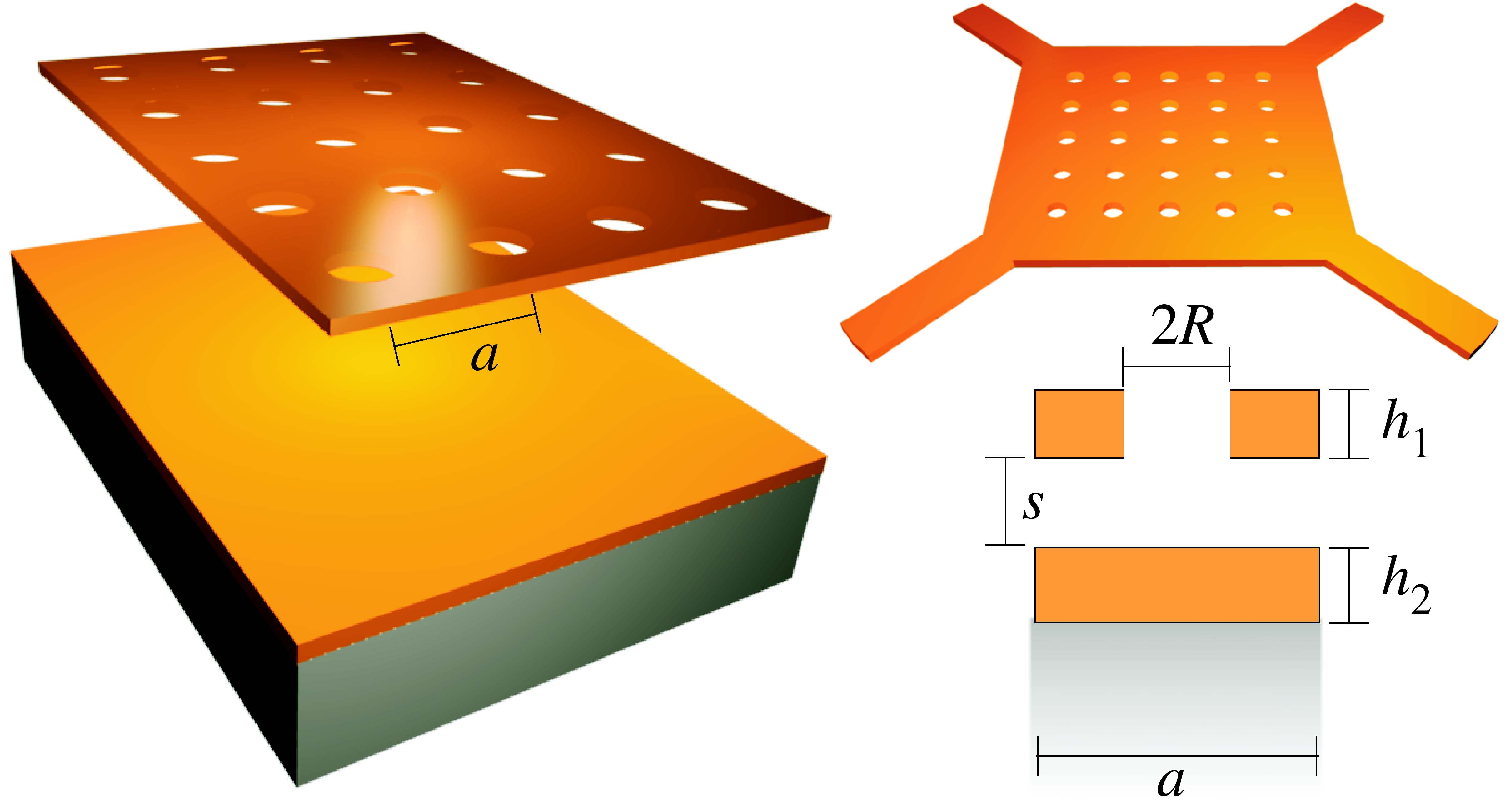
The coupling of the electromagnetic field and matter can give rise to optical forces on otherwise neutral objects [1, 2, 3, 4, 5], and optomechanical coupling via radiation pressure or gradient forces in nanophotonics has been the subject of numerous recent theoretical and experimental works [6, 7, 8, 9, 10, 11, 12, 13, 14, 15, 16, 17, 18, 19, 4, 20, 21, 22, 23, 24, 25, 26, 27, 28, 29, 30, 31]. For example, two identical (symmetric) waveguides or membranes can attract or repel depending on the phase and frequency with which they are excited [32, 33, 5, 14, 34, 35], and this prediction led to several experimental realizations [4, 20, 19, 26]. Here, we extend this concept to greater generality by demonstrating that tunable attractive and repulsive forces can also arise in highly asymmetric structures coupled to external radiation, combining a suspended holey membrane with an unpatterned layered substrate, forming two coupled planar waveguides as shown in Fig. 1. Such asymmetric geometries have a clear advantage in ease of fabrication and experimental characterization compared to symmetric double-membrane structures (in which two membranes must be both patterned and suspended). Although our system is asymmetrical, repulsive/attractive forces can still be thought of as arising from the bonding/anti-bonding level repulsion of guided-wave resonances similar to the phenomenon studied in symmetric systems [5, 23, 24]. In contrast to the symmetric case, however, it is more difficult to identify precisely which resonant modes of the large-separation (isolated) waveguides participate to produce a resonant force, especially at higher frequencies, since the absence of exact degeneracies means that many more modes can potentially interact. Unlike symmetric systems, however, we can obtain bonding/antibonding forces that either increase or decrease with separation and more generally are nonmonotonic. We analyze the resonant forces from the perspective of perturbation theory. In unpatterned multilayer systems, we prove that only repulsive (not attractive) resonances can occur. Although experimental characterization of forces in any membrane system requires accurate measurement of the membrane displacement, we point out that the transmission/reflection resonances of the membrane itself can be used as a sensitive position sensor. Finally, in contrast to previous theoretical works that relied primarily on frequency-domain calculations, we propose a time-domain stress-tensor computational method that obtains the entire force spectrum from a single calculation via Fourier transforms of a short pulse.
Optical forces can arise due to radiation pressure or gradient forces [3, 36]. Radiation pressure can be thought of as exchange of momentum between a photon (momentum ) and matter, and as a consequence it is easily seen that light with incident power exerts a force on a planar surface if the light is 100% absorbed or a force if it is 100% reflected. Therefore, the ratio is a useful dimensionless measure of the strength of an optical force. Gradient forces, as shown recently [5], can arise from the evanescent interaction between localized optical modes, and the resonant increase in the field intensity greatly enhances the force for a given input power [37], so that . Such large forces enable strong, tunable optomechanical interactions [38, 39, 36, 13, 15, 22, 28], which have applications such as optical cooling [40, 1, 8, 12, 41, 42], optical tweezers and traps [43, 44, 45, 3, 46, 47], and optical switches [9, 27]. Successful demonstrations of other prominent resonant optomechanical effects include coherent mechanical oscillation (amplification) of mesoscopic objects with long vibrational lifetimes, and demonstrations of the photon–phonon strong-coupling regime via dressed optical states [36, 48, 28, 49].
We showed in Ref. [5] that if two identical waveguides or resonant cavities are bought together, the mutual interaction of these (degenerate) resonances or guided modes can induce a splitting of the modes into pairs characterized by attractive and repulsive mechanical forces, analogous to the well-known bonding/anti-bonding states formed by the level splitting (avoided crossings) of interacting degenerate states in quantum systems [50]. In submicron-scale photonic devices, these forces are strong enough to yield displacements and other mechanical effects that have been observed experimentally [4, 20, 19, 26]. Furthermore, the frequency and/or phase of the optical excitation can be controlled to yield tunable optomechanical effects, even switching the sign of the force from attractive to repulsive. There are two ways to induce repulsive and attractive interactions, depending on whether the incident power comes in the form of a guided mode or external radiation (the focus of this paper). First, one can inject light parallel to the membranes/waveguides, exciting guided modes that propagate along the waveguides and interact evanescently. In this case, the sign of the interaction is controlled by the relative phase of the modes in the two waveguides [5, 14, 34, 35]. A similar effect occurs by controlling the relative phase of two coupled cavities (e.g. microspheres or microdisks), but in this case the bonding/anti-bonding resonances also have different frequencies that can be used to control the sign of the force [37, 20, 51]. It is also possible to design asymmetric waveguide/cavity structures (e.g. a dielectric waveguide and a microdisk resonator) with repulsive and attractive interactions as long as both structures support propagating modes, again with light incident along the waveguide direction [4, 30]. (Coupled propagating modes in asymmetric geometries were also recently shown to lead to non-monotonic forces [52].) Second, one can shine light perpendicular to the membranes; if the membranes are perforated by periodic holes (or any other periodic modulation), normally incident radiation can couple via diffraction to guided-mode resonances within the membranes, which again couple evanescently. In this case, because the bonding/anti-bonding resonances have different frequencies, the sign of the force can be controlled by the frequency of the incident light. (By considering lateral shifts, one can also obtain lateral forces and other effects [24].) As the periodic modulation (e.g. the hole radius) is made smaller, the lifetime (or quality factor ) of the guided-wave resonances increases [24], the resonant fields become stronger (intensity ), and thus the resonant forces become stronger (albeit narrower in bandwidth ). This force enhancement is ultimately limited only by losses (absorption or scattering from finite size or disorder). Another limitation is that the narrow bandwidth translates into a sensitive dependence of the force on the separation of the two membranes (since the resonant frequency shifts with separation).
As indicated in Fig. 1, this paper considers the case of normal-incidence light on a suspended membrane, but in contrast to previous works, we only have a single suspended membrane (e.g. silicon) over a solid unpatterned substrate. The substrate must still support a guided mode of its own in order to obtain forces by evanescent coupling, and in our case this is achieved by a layered structure of a higher index layer on a lower-index substrate (e.g. silicon on silica). As in previous works, the membrane is periodically patterned to couple resonantly with normal-incidence light, and thanks to evanescent coupling this periodicity is also sufficient to couple light to guided resonances in the unpatterned substrate. Because the two waveguides in our case are so different, however, the interaction is more complicated than the degenerate level-splitting that occurs in symmetric systems, leading to nonmonotonic force dependences as well as transitions in the sign of the force. The separation and frequency dependence of the force in membrane structures has been previously exploited for achieving a variety of optomechanical effects. For example, one can obtain mechanical oscillators with dynamically tunable “spring constants,” even flipping the sign to yield an unstable equilibrium and mechanical bistability, with a tunable relative strength of the linear and nonlinear terms (with arbitrarily strong relative nonlinearity possible if the linear term is canceled) [38, 39, 36, 13, 15, 22, 28]. Here, we point out that by operating with light consisting of two frequencies, rather than a single frequency, one can tailor the spring constant of the membrane without changing its mechanical equilibrium separation. Furthermore, we argue that, with appropriate design, it should be possible for repulsion to dynamically activate at small separations, creating a feedback mechanism for combating stiction arising from other forces (e.g. electrostatic [53, 54] or quantum [55, 56] interactions).
2 Computational Method
Previous numerical methods for computing optical forces have mainly focused on frequency-domain approaches, with some exceptions [57, 58, 59]. Given two objects separated by a distance , the force on one of the objects can be computed in one of at least two ways: One approach involves computing the derivative of the eigenfrequencies of two membranes separated by distance as a function of , which can be related to the force via the relation [5, 37], where corresponds to repulsion. Ref. [60] generalized this formula to handle the case of resonances with finite lifetimes , rigorously justifying our earlier suggestion [37] that the change in lifetime with separation has a negligible (higher-order) contribution to the force on resonance. This approach is problematic, however, in general circumstances where there may not be well-defined resonant modes with negligible loss, nor does it include cases where there is a superposition of the resonant mode with other waves (e.g. light from an external source). Another approach involves computing the force via an integral of the time-average Maxwell stress tensor
| (1) |
around some bounding surface lying in vacuum [2]. For resonant modes with negligible loss, can be computed directly from an eigenmode calculation [23]. More generally, including the case where the fields are excited from an external source whose effect must be included from some time-harmonic current source , one can solve a set of linear equations for the resulting time-harmonic fields and by a variety of methods (e.g. finite elements or differences in the frequency domain, or transfer-matrix methods) [61, appendix D], and use these fields to compute [10, 62, 63, 26, 64]. This approach, however, has the drawback that if the force at many frequencies is desired, one must perform many separate calculations (one for each ).
If a broad-band force spectrum is desired, an attractive alternative is to compute the stress tensor via the Fourier transform of a short pulse in the time domain (e.g. finite-difference time-domain, FDTD [65]), yielding the entire frequency spectrum at once. Here, one simply evolves Maxwell’s equations in response to a pulse source [e.g. ] in time, accumulating the discrete-time Fourier-transform [] of both the electric and magnetic fields over the stress-tensor surface , and at all desired frequencies [66, 67]. These Fourier-transformed fields then yield the stress tensor and hence the force. Of course, the force must be normalized in some way, and here the dimensionless normalization is very convenient. One simply does a separate calculation, with no structure (vacuum), to compute the Fourier-transformed incident fields and hence the incident power . Dividing yields the dimensionless force spectrum, where all arbitrary normalization factors (e.g. the incident pulse spectrum or the normalization of the Fourier transform) have canceled. (Matters are more complicated in a nonlinear system, of course.)
In what follows, we exploit our FDTD approach to compute forces on the geometry of Fig. 1. All of the subsequent calculations were performed using MEEP, a free FDTD simulation software package develped at MIT [67]. We find that discretization errors coming from our finite resolution of 40 pixels/ affect the computed force spectra by no more than a few percent.
3 Membrane Forces
In this section, we explore attractive and repulsive resonances in the asymmetric membrane structure of Fig. 1, along with possible applications and the underlying theory.
3.1 Symmetric and asymmetric systems
We begin by considering two related membrane structures: the asymmetric structure of Fig. 1, with a perforated silicon membrane over a silica substrate; and also a symmetrized version consisting of two identical perforated silicon membranes, examined previously by Ref. [24]. In both cases, the membranes are illuminated from above by normal-incident ( direction) light polarized in the direction, and we consider the resonant frequencies and the resulting forces as a function of frequency and separation.
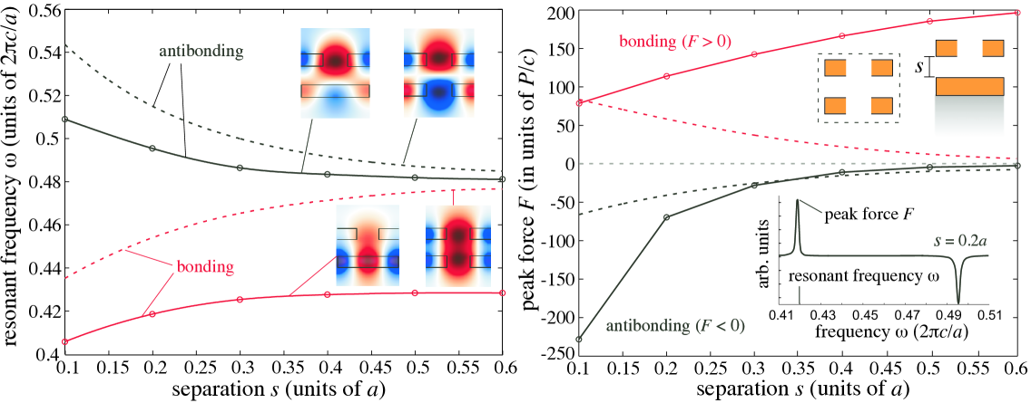
In the symmetric case, it is well known that each resonance of the individual membranes splits into two resonances of the coupled two-membrane system: “bonding” and “anti-bonding” modes, in which the individual resonances are excited in phase and out of phase, respectively [5]. The frequencies of these two resonances as a function of membrane separation are shown as dashed lines in the left plot of Fig. 2, and as expected the frequency splitting vanishes as the separation increases (and hence the membrane coupling decreases) [5]. The corresponding field patterns are shown as the right two insets of the left plot, and display the expected phases. Each resonant mode corresponds to a resonant peak in the optical force, and this peak force (at the resonant frequency) is plotted as a function of separation as dashed lines in the right part of Fig. 2. As expected, the bonding and anti-bonding modes correspond to opposite-sign attractive and repulsive forces between the membranes, respectively, and the force becomes stronger as the separation decreases (increasing the membrane interactions). The attractive force in the bonding case has slightly larger magnitude than the anti-bonding repulsion, which can be explained by the larger field overlap in the former case due to the lack of a node in between the membranes [37, 33].
In the asymmetric case, the mode of the isolated membrane is not the same frequency as the corresponding guided mode of the isolated layered-substrate structure (although the parameters can be adjusted to force a degeneracy if desired). The mode of the silicon on silica (oxide) system is actually a lossless waveguide mode (lifetime ), not a resonance; it is only when the membrane is brought into proximity with the oxide that the membrane’s periodicity allows guided modes at wavevector (and multiples thereof) to couple to normal-incident radiation [61]. In this case, the layered-substrate (waveguide) mode that is nearest in frequency to the isolated-membrane resonance frequency is the lowest-order waveguide mode of wavevector . Because the two mode frequencies are no longer degenerate, when the resonant frequencies of the asymmetric case are plotted versus separation as solid lines in the left part of Fig. 2, the frequency splitting no longer vanishes as the separation increases. Nevertheless, there is a frequency splitting or “level repulsion,” explained below in terms of second-order perturbation theory, which becomes significant for small separations, and the corresponding field patterns display the qualitative phase characteristics of bonding/anti-bonding modes (insets). As a consequence, as considered theoretically below, the force spectrum in the asymmetric case (right, inset) indeed displays the characteristic attractive and repulsive resonant peaks of bonding/anti-bonding modes. The peak force (at resonance) versus separation is plotted as solid lines in the right part of Fig. 2, and has similar sign as in the symmetric case. Of course, the system is now more complicated than the symmetric case in a variety of ways (e.g. the field patterns are no longer symmetrical/anti-symmetrical and the lifetimes as well as the frequencies depend strongly on separation), so the peak force versus separation dependence is significantly different: First, the peak bonding (attractive) force decreases as decreases and reaches a constant value as . Second, the ratio of the antibonding (repulsive) to bonding force becomes increasingly larger at smaller separations (e.g. it is more than a factor of 2 larger at ), in contrast to what is normally observed [37, 33].
To understand these features of the force, we use the fact (reviewed in Sec. 3.3) that the force is proportional to both the separation () dependence of the frequency and also the lifetime . As discussed below, perturbation theory indicates that of a nondegenerate mode in one object decreases proportional to the square of its field overlap with the other object [68]. For a mode which as approaches a leaky mode of the perforated membrane—in our case, the antibonding mode—the lifetime asymptotes to a nonzero constant and hence the product ; correspondingly, the force tends exponentially to zero with . Similarly, the force must tend to zero for both the bonding and antibonding modes of a symmetric membrane (where all modes are leaky as ). On the other hand, for a mode that asymptotes as to a lossless guided mode of the unpatterned substrate—in this case, the bonding mode—the lifetime diverges as . In fact, perturbative scattering theory [68] indicates that the scattered power, and hence [61], is proportional to the square of the field overlap with the periodic membrane (the source of the scattering loss). Hence diverges at the same rate at which vanishes, and thus the force should asymptote to a nonzero constant as . These behaviors are precisely what is observed in Fig. 2 (right): the peak forces of the symmetric system and the asymmetric antibonding mode decrease monotonically to zero with increasing , while the peak force of the asymmetric bonding mode increases monotonically to a constant with increasing . The corresponding variation in is shown in Fig. 3 (left). Note that for , the of the antibonding mode increases rapidly with decreasing , leading to an increasing antibonding force that is many times larger than the corresponding bonding force. In a practical system, the behavior of the bonding mode will be further modified by the presence of loss in the isolated-substrate guided mode (from finite-size effects, roughness, absorption, etcetera)—this will cause its to saturate to a finite value. In this case, the force will behave nonmonotonically: it will initially increase, but will then decrease to zero as goes beyond the saturation point of (while continues to decrease). Thus, the lifetimes of both the membrane and substrate could be exploited to tailor the dependence of the force in this and other similar systems.
3.2 Tunable mechanical properties
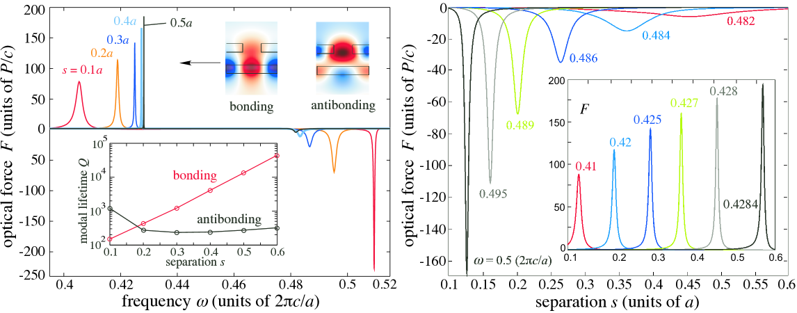
Because the frequency and magnitude of the resonant forces change as is varied, it is interesting to study also the separation dependence of the force for light incident at a single frequency, which alters the mechanical dynamics of the membrane. Here, we consider the effect of light incident at a single frequency, and then extend our analysis to the case of two frequencies. (More generally, it may prove interesting to study the dynamics of the membrane for modulated pulses.) Figure 3 plots the optical force as a function of separation for incident light at various frequencies . As expected, the lifetime of the attractive peak, with concentrated in the layered substrate (shown on the inset), becomes infinite () as due to the reduced coupling between the infinite- substrate mode and the finite- PhC resonance. At a fixed frequency, changing can move the system into or out of resonance, leading to a dramatic -dependence of the force. (Indeed, the dependence can be much sharper than shown here, e.g. if the hole diameter is shrunk to increase the of the resonances.) One can obtain transitions in the sign of the force, from attractive to repulsive and vice versa, as is varied, leading to stable and unstable equilibria, not yet including the mechanical restoring force from the membrane supports, and even multiple equilibria.
When mechanical forces are included, two things can happen. If the optical force is nonzero, the mechanical equilibrium point of the membrane will shift and the slope of the force curve (the spring constant ) will be altered. If one operates at a point where the optical force is zero, then the equilibrium position is unaltered but the spring constant is changed. The total spring constant, including linear mechanical restoring forces on the membrane, will be given by , where denotes the mechanical spring constant. Whereas is frequency- and power-independent, exhibits a very sensitive dependence on both, and therefore by choosing and the incident power it is possible to tune the total spring constant of the system [69, 70, 71, 72]. On the one hand, if one chooses so that , then optical forces act to increase and therefore stiffen the stable equilibrium. In systems driven by undesirable thermal fluctuations, this effect has been exploited for “cooling” the resulting vibrations [73, 20, 30]. On the other hand, if one chooses so that , then can be decreased and even flip sign as the optical power increases, leading to an unstable equilibrium and bistable behavior [69, 71]. Near an exact cancellation , the linear term in the -dependence of the force is decreased relative to the higher-order nonlinear terms (which include both optical and mechanical terms), allowing arbitrarily strong nonlinear mechanical effects, and even a strictly nonlinear regime of operation () where effects like bistability, hysteresis, and frequency conversion should be readily observable [74, 36].
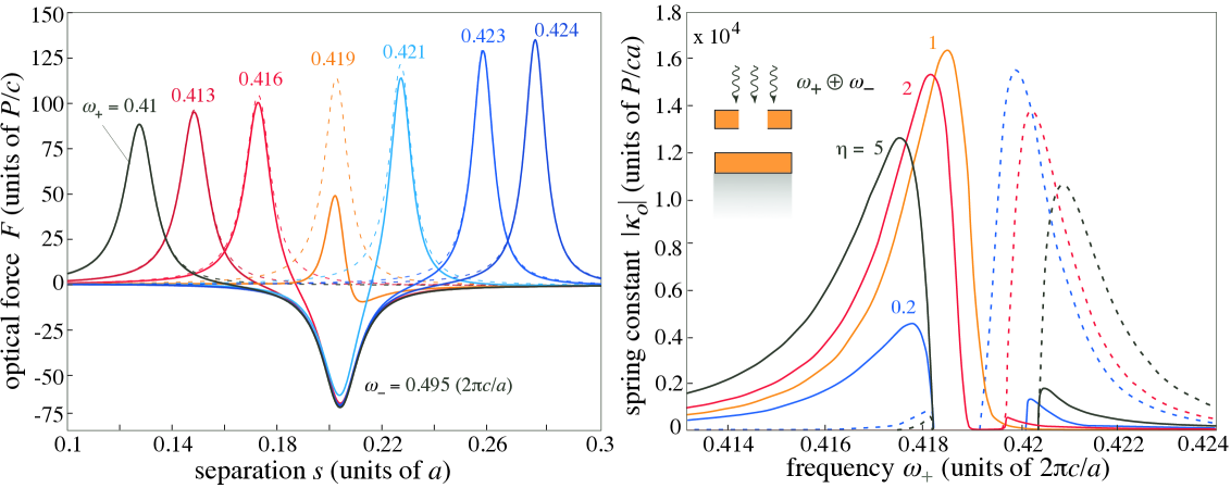
For light incident at a single frequency , sign transitions in the force occur as the structure moves toward or past a force resonance, as illustrated in Fig. 3. Away from these resonances, the “background” dimensionless force is attractive and bounded from above by (see Sec. 4), leading to negligible optical spring constants (small ) at the corresponding equilibria separations [see Fig. 3 (inset)]. This generally does not preclude a strong modification of the mechanical properties of the membrane (achieving large ) since it is also possible to operate at separations where is large and has linear slope (), although this inevitably causes a change in the initial mechanical equilibrium separation of the membrane [39]. For applications in which achieving a large without modifying the initial mechanical separation (i.e. achieving a large at a position where ) is important, then a different scheme is required. For example, rather than operating with incident light at a single frequency , one can instead consider the combined effect of light incident at two different frequencies and , near the attractive (bonding) and repulsive (antibonding) resonances, respectively. This idea is illustrated in Fig. 4 (left), which shows the optical force as a function of separation for incident light of power consisting of two frequencies, [chosen in the region ] and , of corresponding power and , respectively. From Fig. 3, it is clear that incident light at leads to a repulsive peak at whereas incident light in the range leads to attractive resonances in the range . As the attractive and repulsive peaks excited by and come close to one another, the transitions in the sign of the force become more pronounced, leading to larger . To quantify the enhancement in the spring constant, Fig. 4 (right) plots the absolute value of the optical spring constant (units of ) as a function of , for different values of the ratio of power in versus , where dashed/solid lines correspond to negative (unstable) and positive (stable) , demonstrating orders-of-magnitude enhancement in . For example, the peak spring constant in the case where is , whereas it is smaller than in the case of incident light only at , corresponding to . An alternative scheme that allows tailoring of the optical spring constant near equilibrium was explored in Ref. [51], although in that case the effect is achieved by the presence of multiple bonding/antibonding pairs in which opposite-sign force resonances were designed to occur at closely spaced frequencies, whereas here there is no need for the resonances to be closely spaced.
Additional forces on the membrane arise at small separations due to residual static charges and also due to quantum/thermal fluctuations (Casimir and van der Waals forces), which are typically attractive [75, 76, 77, 78] and may lead to “stiction” problems in micromechanical (MEMS) systems where moving parts are forced into contact [55, 56, 79]. Here, the separation dependence of the classical optical force can potentially be used to combat such stiction effects [80, 81]. Not only can one exploit a repulsive resonance to oppose stiction, but the separation dependence means that such a repulsion can be designed to take effect only if inadvertently falls below some threshold. That is, a repulsive resonance for small can be used as a feedback effect to reduce the chance of stiction without significantly altering the mechanical dynamics at larger where the incident light is out of resonance. In an upcoming manuscript, we will demonstrate how these effects can also be exploited to design integrated, all-optical 111The interaction of normal-incident light with the membrane in this system can be exploited to simultaneously control and measure the membrane’s equilibrium separation. and accurate techniques for measuring the Casimir effect that rely on measuring static displacements rather than forces or force gradients.
Figures 3 and 4 only show a small sample of the kinds of optical effects that can be observed in evanescently-coupled systems. In particular, there are many degrees of freedom and possibilities to explore, especially if one is not restricted to symmetric structures or operating at a single frequency. For example, the magnitude of the optical forces shown in Fig. 3 are by no means the largest possible, since larger forces can be obtained merely by increasing at the expense of bandwidth (and insensitivity). Even more complicated behaviors can be obtained by increasing the number of resonances, and the choice of resonance offers a corresponding choice of lengthscales or operating frequencies.
3.3 Level repulsion in asymmetric membranes
For well-defined (long lifetime) resonant modes, perturbation theory has been used to analyze the relationship between the force and the resonant frequency/lifetime [37, 34, 72], and this relationship can also be used to illuminate the relationship between the sign of the force and the field distribution, as well as the physical origin of resonant repulsion.
As long as the interactions in the system are dominated by a discrete set of well defined leaky resonances (lifetime 1/period), then one can apply standard methods of discrete-spectrum time-independent perturbation theory [68]. (For non-resonant systems with a continuum of non-localized modes participating at every frequency, perturbative methods are much more complicated [82].) In this case, we proceed in three steps: first, we relate the force to the -dependence of the resonant frequency (generalizing a previous result [37]); second, we connect to the electric-field distribution of the resonance; third, we incorporate the level-repulsion effects of nearby resonances via second-order perturbation theory. There is one important complication that arises in resonant systems which does not arise in the lossless guided modes where effects were previously derived: the quality factor (lifetime ) of the resonances may in general also vary with separation. Ref. [60] considered the effect on the force due to changes in both and and found generally that at resonance (including the structure considered here), effects have little if any effect on the force (being higher order in , as we previously suggested without proof [37]). We therefore neglect in the following, in which case the expression for the force is:
| (2) |
where denotes a repulsive force. Although Eq. (2) is derived rigorously from coupled-mode theory in Ref. [60], a simple justification for the same result can be obtained if one neglects radiative or absorptive losses, to treat the resonator as a closed system (i.e. equivalent to changing the separation slowly compared to but quickly compared to the lifetime). Given an incident power , the energy stored in a resonance of real frequency and quality factor is (by definition of [61]) given by . Neglecting radiation loss, any change in the energy must be due to a mechanical force , resulting in Eq. (2). Equivalently, , a result we previously derived for guided () modes [5].
The dependence of on can be predicted by perturbation theory. In particular, the first-order change to the frequency coming from a small change in the permittivity of a system with original permittivity is readily expressed as:
| (3) |
In this case, however, is not small: at a given point near the interface, is changing discontinuously as that interface moves past the point. In this case, perturbation theory must be derived more carefully [68]. For an interface from to that is moving by (towards ), assuming isotropic materials, the numerator of Eq. (3) changes to:
| (4) |
Without loss of generality, we can hold the upper membrane fixed and move the substrate (or lower membrane) away by . From Eq. (4), the way to obtain attractive () and repulsive () resonant effects is clear. If we hold one membrane fixed and move the substrate (or the other membrane), will be positive (attractive) if is peaked where , i.e. on the air/silicon interface (adjacent to the upper membrane). Conversely, will be negative (repulsive) if is peaked where , i.e. on the silicon/oxide interface (away from the upper membrane). Precisely such field patterns can be observed in the insets of Fig. 2 and Fig. 3: the repulsive and attractive modes have peaked at the expected interfaces. Note that a homogeneous substrate, e.g. semi-infinite silicon or oxide, has no interface except for the air interface adjacent to the upper membrane, so in this case a repulsive force cannot arise by this mechanism, as demonstrated for the case on the inset of Fig. 5 below. An exception to this rule is discussed in Sec. 4, in which repulsive forces arising from radiative modes are analyzed, a situation where a lack of normalizability causes the perturbation theory to break down.
The above discussion indicates which field patterns might be expected to lead to repulsion and attraction, but does not explain how such field patterns can arise. For the case of a symmetric membrane, symmetry considerations predict that the degenerate modes of two isolated membranes will split into even/odd bonding/anti-bonding pairs by degenerate first-order perturbation theory [83]. The presence of a nodal plane bisecting the anti-bonding mode (assuming its field is dominated by and not ) means that the field pattern will be stronger on the far sides of the membranes, leading to a repulsive interaction as observed in Fig. 2 and Fig. 3, and as predicted above. For asymmetric membranes, however, there is typically no degeneracy, and the corresponding two-mode interaction must instead be analyzed by second-order perturbation theory, which plays a role for sufficiently small separations (large interactions). When two isolated waveguides each have a mode with nearby frequencies, and one brings the waveguides together so that the mode fields overlap, second-order perturbation theory predicts a contribution to that tends to split the two frequencies:
(As above, the overlap integrals are modified into and components for motion of discontinuous interfaces [68].) Note that the term pushes away from , and becomes stronger as the frequencies become closer (with the most dramatic case being degenerate modes, where the derivation is modified). Because of the competition between the first- and second-order terms, which may be comparable in magnitude for small separations (large overlaps), it is possible for the force near a resonance to switch signs with separation, a possibility that is demonstrated in Sec. 3.4 below.
3.4 Multi-modal interactions
Previously, we considered resonances at a relatively low frequency (compared to ), where the only relevant interactions were between two modes (one for each isolated membrane or substrate). At higher frequencies, the density of states generally increases, and thus many more resonant modes are typically present. Correspondingly, the inter-modal interactions become more complicated, and it is not always possible to identify individual pairs of bonding/anti-bonding modes. However, the qualitative features of repulsive and attractive resonances are still present, although the additional complexity provides more degrees of freedom leading to more complicated force phenomena.
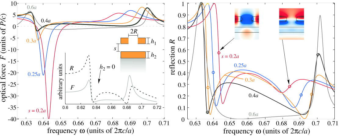
For example, the force and reflection spectra for the asymmetric membrane system of Fig. 1 are shown in Fig. 5 in a higher frequency window (about double the frequencies in Fig. 3). As before, the force spectrum (left) shows both repulsive and attractive resonances. In this case, however, we actually observe a force resonance changing sign as a function of separation, which physically can be interpreted as different terms dominating in the perturbation theory [Eq. (3.3)] at different separations. In the reflection spectrum (right), these resonances correspond to Fano shapes (adjacent peaks and dips), a well-known consequence of the coherent combination of a resonant process with direct transmission through the slabs [84, 9, 24]. Because the reflection spectrum depends sensitively on the separation, the peak locations from a broad-bandwidth low-intensity source could be used to accurately determine the separation in an experiment. Note also that the resonant peaks in this frequency window approach one another as the separation decreases, which means that the largest contribution to level repulsion in this case is coming from interactions with other modes (outside this frequency window, not shown); this is verified by examining the field patterns (upper insets), which clearly correspond to completely different modes in the membrane and not just a relative-phase change. As in Sec. 3.2, fixing the frequency and plotting the force versus separation reveals a force that changes both magnitude and sign as a function of separation.
In the absence of a guided mode in the substrate, the physics of this situation is completely changed—one no longer has level repulsion effects, since there are only resonances in the membrane. A general argument for the attractive nature of the resonant force is given in the previous section. This occurs, for example, if the oxide substrate is replaced simply by a low-index (oxide, ) substrate, which supports no guided modes of any kind on its own. However, the resonant frequencies (and lifetimes) of the membrane are still modified by the proximity of the substrate, so there is still a resonant force, and in this particular geometry we find that the resonant force is always attractive. Such attractive forces can however be exploited in integrated photonic devices as a way of tuning the mechanical response of the devices [85, 52]. The force and reflection spectra for this case are plotted in the middle inset of Fig. 5 (left), for a particular separation .
4 Fabry–Perot Forces
Our focus thus far has been on periodic structures supporting resonances whose coupling leads to both enhanced attractive and repulsive forces. However, at large separations compared to the evanescent tail of the participating guided modes, evanescent bonding/anti-bonding effects lead to negligible force enhancement. On the other hand, there exists an alternative and complementary force-enhancement mechanism that can play a role at large separations: light normally incident on two separated planar objects can be resonantly enhanced due to the Fabry–Perot cavity formed between the objects by reflections from adjacent surfaces of the objects, and the extent of this enhancement will increase with the reflectivity of the objects (i.e. with the of the cavity). Although such Fabry–Perot force-enhancement mechanisms have been considered in previous work [86, 87, 74, 88, 89, 20], in applications ranging from gravitational-wave detection [90] to optical cooling [91, 92, 93, 94, 42], it is interesting to explicitly compare the two resonant mechanisms. In this section, we briefly consider the kinds of repulsive and attractive forces that can arise in systems consisting of unpatterned multilayer objects, emphasizing some of their similarities and differences compared to forces arising from evanescently coupled resonances.

Resonant radiation pressure within Fabry–Perot cavities has a long history, dating back to work in the 1960s on interferometer sensitivity [95], and has since been considered both theoretically and experimentally for many applications [88, 36], such as nonreciprocal phenomena [96], optical cooling [92, 94, 93], and tunable optical springs [47]. If the space between two partially reflecting mirrors (e.g. Bragg mirrors) is viewed as a waveguide, then the resonance frequency for normal-incident light corresponds to a slow-light (zero group-velocity) band edge where radiation pressure is enhanced [70, 88]. In all of these cases, the pressure is repulsive, as one might expect for light bouncing between the two objects (and was argued in general for two semi-infinite objects [64]). We show this in general below, for radiating modes (not guided modes) and any unpatterned multi-layered structure (in the absence of gain).
Here, we consider a general class of geometries, depicted in Fig. 6, consisting of two unpatterned (translationally invariant in two directions) planar multilayer objects separated by distance in vacuum, denoted as objects (1) and (2), characterized by complex reflection/transmission amplitudes and at a given frequency, respectively (satisfying in the absence of absorption or gain). The dimensionless force on object (1) due to light normally incident from above at frequency can be readily computed (using a simple transfer-matrix analysis to obtain the stress tensor [97]) to be:
| (5) |
where is the induced field at the lower interface of object (1), and is the phase associated with the air gap.
Elementary manipulation of Eq. (5) shows that the force is bounded above by , which is a bound on the attractive (positive) force. This result is a physical consequence of conservation of momentum: the light trapped between the objects can only act to repel them, whereas an attractive force can only arise from reflections from the uppermost surface. (The key difference compared to patterned membranes or guided modes is that the fields in between the objects are now purely propagating waves in which the field amplitude is proportional to the wave momentum [2], with no evanescent component where these two quantities can be decoupled.) The maximum reflectivity is 100%, corresponding to . A related situation is one in which the lower object plays no role because its reflectivity approaches zero. In this case, for and , one recovers a standard result for the force on a single object, [95], which is always positive (attractive) and is bounded above by 2. (Note, however, that all of these limits only apply in the absence of gain, which can alter the force by emitting additional photons from the objects [98].) On the other hand, the repulsive forces are unbounded, becoming arbitrarily large as and approach unity. This is simply a consequence of the repulsive pressure from the Fabry–Perot mode trapped between the objects, whose lifetime (and energy density) diverge in this limit. This familiar result has been exploited in many cavity-enhanced optomechanical systems as noted above.
One can construct multilayer objects supporting exponentially localized resonances which couple to normally incident radiation. For example, this is the case if each object consists of a multilayer Bragg mirror with an embedded defect layer [61]. In this case, degenerate perturbation theory implies that two symmetric objects [such as those in Fig. 6 (right)], each with an identical embedded defect/resonance, should couple to form bonding/anti-bonding states where the resonances are in/out-of phase. Naively, one might suppose that this will lead to repulsive and attractive resonances, as in the coupled guided-mode case, but Eq. (5) indicates that this is impossible. The explanation is straightforward: although such defect modes are exponentially localized within the Bragg mirrors composing each object, they are propagating in the region between the objects where there are no mirrors (because the input beam is propagating in free space and no diffraction occurs). This means that the frequency splitting does not depend exponentially on the separation between the two objects, and hence there is no resonant force enhancement via these modes, by the analysis of Sec. 3.
5 Conclusion
Optomechanical interactions are a rich subject of current research, and the use of evanescently coupled guided resonances enables an especially rich set of phenomena because of the presence of both attractive and repulsive resonances. The ability to tailor and exploit guided resonances coupled via periodic modulations offers an exciting opportunity to procure complicated force effects at small separations. In this paper, we showed that functionality similar to that of previously studied symmetric-membrane systems can be obtained in asymmetrical membrane-substrate structures. From an experimental point of view, such asymmetrical structures are attractive in that only a single membrane need be suspended and patterned. From a theoretical viewpoint, because the resonant modes of asymmetrical structures need not come in degenerate pairs (unless degeneracies are forced), more than one pair of modes can have strong interactions, leading to the possibility of richer force phenomena [51]. Correspondingly, the distance dependence of a force spectrum with multiple attractive and repulsive resonances can exhibit richer “optical spring” phenomena than are possible with repulsive resonances alone (as in Fabry–Perot resonances between mirrors); for example, one can operate at a zero of the optical force to tune the optical spring constant (in either direction) without altering the equilibrium position.
Acknowledgements
We are grateful to Aristeidis Karalis and Peter Bermel at MIT for useful discussions. This work was supported by the Army Research Office through the ISN under Contract No. W911NF-07-D-0004, and by the Defense Advanced Research Projects Agency (DARPA) under contract N66001-09-1-2070-DOD.