Spring-block approach for nanobristle patterns
Abstract
A two dimensional spring-block type model is used to model capillarity driven self-organization of nanobristles. The model reveals the role of capillarity and van der Waals forces in the pattern formation mechanism. By taking into account the relevant interactions several type of experimentally observed patterns are qualitatively well reproduced. The model offers the possibility to generate on computer novel nanobristle based structures, offering hints for designing further experiments.
keywords:
self-assembled nanostructures , spring-block models , pattern formation , nanotubesReproducible nanoscale patterns and structures are of wide interest nowadays for engineering components in modern small-scale electronic, optical and magnetic devices [1]. The so-called bottom up approach for the fabrication of these nanostructures uses nanoparticles as elementary building blocks. Under some specific conditions the nanoparticles self-organize into the desired structures [2]. A well-known and widely explored possibility to induce this self-organization is to use the capillarity forces which appear during the drying of a liquid suspension of nanoparticles [3, 4]. For instance, regular and irregular two-dimensional polystyrene nanosphere arrays on silica substrates are generated by such methods [5]. These patterns are used then as a convenient mask in the NanoSphere Litography (NSL) method.
Carbon nanotubes (CNT) are attractive materials for nanotechnology because of their interesting physico-chemical properties and molecular symmetries. In order to make them appropriate for certain applications, proper initial CNT configurations have to be built, and specific conditions have to be found which enable their controlled self-organization [6, 7, 8]. This is a very ambitious and challenging task, which can be made easier by elaborating working computer models for the self-organization of CNTs on substrates. Therefore, not only experimental, but also computational studies can advance the field of nanoengineering.
In the work of Chakrapani et al. [9] an experimental procedure is presented in which capillary self-organization of CNTs leads to puzzling cellular patterns. After the collapse and reassembly of the highly ordered, anisotropic, elastic CNTs, shrinkage and crack formation occurs. The resulting cellular foams are visually striking, stable patterns.
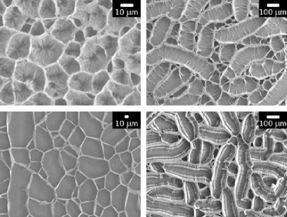
The experimental procedure [9] may be shortly summarized as follows. Multi-walled nanotube arrays are grown on rigid silica surface by chemical vapor deposition (CVD) based on the decomposition of ferrocene and xylene. The resulting nanotubes have a wall thickness of ca. 10nm and a diameter of ca. 30nm. The average distance between two nanotubes is ca. 50nm. The obtained nanotube bristle is oxidized in an oxygen plasma at room temperature and 133 Pa pressure for 10 minutes and immersed in a wetting fluid. After the liquid evaporates, characteristic cellular type patterns are formed, i.e. the ends of nanotubes self-organize in compact walls.
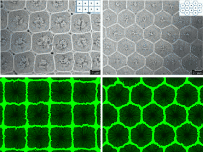
Figure 1. shows scanning electron microscope images of some typical structures. From the figures we learn that a wide variety of structures are engineered in such manner. Both statistically symmetric polygonal cells and rather elongated ones can be obtained by chaning the experimental conditions.
These micrometer scale structures have many advantageous features. They can be elastically deformed, transferred to other substrates or floated out to produce free-standing macroscopic fabrics. Thus, they might find potential applications as shock absorbent reinforcement in nanofiltration devices, elastic membranes and fabrics, and containers for storage or growth of biological cells.
Despite of its applications and the existence of well elaborated production protocols, the exact mechanisms responsible for self-organization of CNTs into vertically aligned cellular structures is not clearly understood. Recently, it has been argued that although we lack some basic information regarding the self-organization of CNTs within a bristle, this process can be approximated with the self-organization of arrays of CNT micropillars of micron-scale diameters [10] each consisting of thousands of CNTs. This observation enables the construction of a computationally tractable model which operates instead of stand-alone CNTs with micropillars.
In the present work a simple mechanical spring-block type model defined at mesoscopic micropillar level is considered for understanding the capillarity driven self-organization of nanobristles (or so called “CNT forests”). The aim is to build a model that is able to qualitatively reproduce the variety of experimentally produced patterns.
The model used here for describing the self-organization process of nanobristles is a mesoscopic one and is based on the mechanical spring-block stick-slip model family. This model family appeared in 1967, when R. Burridge and L. Knopoff [11] constructed a simple mechanical model for explaining the Guttenberg-Richter law for the distribution of earthquakes after their magnitude. The basic elements of the model are blocks and springs that interconnect in a lattice-like topology. The blocks can slide with friction on a planar surface. The original system introduced by Burridge and Knopoff (BK) is a one-dimensional model. It can be studied numerically and it exhibits self-organized criticality [12].
The BK model gained new perspectives with the strong development of computers and computer simulation methods. Variants of the BK model proved to be useful in describing complex phenomena where avalanche-like processes are present, pattern formation phenomena and mesoscopic processes in solid-state physics or material sciences [13, 14].
Recently, by using this model, we have succesfully explained the patterns obtained in capillary self-organization of nanospheres [5, 16]. Motivated by this success, hereby we propose to map the capillarity driven self-organization of nanotube bristles to a spring-block system, and to understand the pattern selection process by means of computer simulations.
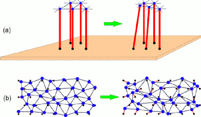
First, let us consider the three-dimensional (3D) model, which is very similar to the real nanotube arrangement. As sketched in Figure 2(a), the micropillars composed by thousands of nanotubes having fixed bottom ends are modeled by flexible strands. Their capillary interactions are represented by non-classical springs that connect the neighboring pillars. The evaporation of the liquid is simulated by the stepwise increase of tension in the springs. This will result in the agglomeration of micropillar ends creating the final structure in the studied system.
As shown in Figure 2(b), this 3D model can be easily mapped into a two-dimensional (2D) one by projecting the micropillars’ top ends on the surface. In the projection plane the micropillars bottom ends are represented as dots, and their positions are fixed on a predefined lattice. The movable top ends are modeled by the disk shaped blocks which can slide with friction on the 2D simulation surface. For visual purposes only, each block is connected by an extensible string with its bottom end showing the micropillars’ trunk. In our simplest approach there is no restriction imposed to the length of these extensible strings which means that nanotubes with infinite length are used. This corresponds to the real case when the nanotubes length is much grater than the linear size of the cells in the final patterns. The blocks (top of micropillars) are connected with their nearest neighbors through special springs that model the resulting forces acting between the micropillars.
.
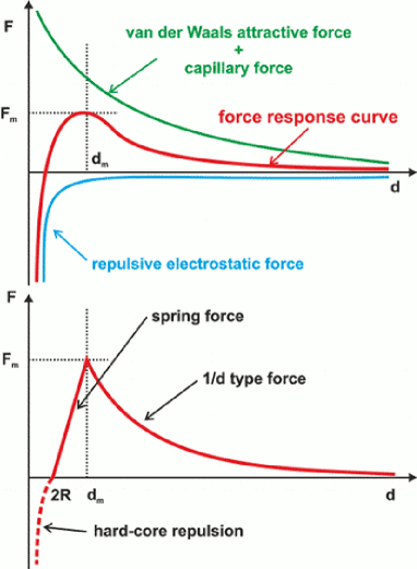
These special springs are one key ingredient of our computational model. They represent the resultant interaction force acting between two micropillars immersed in suspension. The tension force in the spring has a complex variation with the spring-length, it’s form is sketched with a red line in the top panel of Figure 3. This force is the resultant of the capillary force, the electrostatic repulsion and the van der Waals attraction between the micropillars. The form of the capillary force acting between two micro-scale rods wetted by a liquid was measured experimentally and deduced analytically, too [17, 18, 19]. Electrostatic repulsion and van der Waals attraction are successfully described by the Derjaguin-Landau-Verwey-Overbeek theory [20]. The capillary force decays inversely proportionally with distance . The resultant of all these forces reduces to zero for long distances and it has a maximum at distance of micropillars.
Our model approximates this resulting force. The special spring-force used in simulations is shown with solid line in the bottom panel of Figure 3. For small elongations this spring acts as a classical spring with
| (1) |
where is the spring constant and is its equilibrium length. For elongations longer than the spring force decays as
| (2) |
where the constant is selected in such way that the force-elongation curve is continuous at . The maximum of the spring force at is denoted by .
Similarly with our previous models of drying granular materials [15] or self-organizing nanosphere systems [16], the effects created by the evaporation of the liquid is introduced through these springs. As the liquid evaporates the meniscus accounting for the capillarity forces gets more accentuated. This is modeled by a step-by-step increasing of the spring constant . It has to be noted that through the drying process the maximum force in the spring remains unchanged since the electrostatic forces are not affected. Accordingly, with the increasing of the value has to be proportionally lowered.
The second key ingredient of our spring-block model (necessary to get realistic structures) is the capillary force resulting from the non-vertical orientation of micropillars. Once the micropillar becomes inclined, the meniscus radius of the liquid surface in contact with the micropillar becomes grater on the top side than on the bottom side. This leads to an unstable state because a resulting net force pointing vertically downwards will act at the crossing point between the liquid surface and the micropillar [21], tending to incline even more the tube. Here we denoted by the angle between the vertical and the tangent to the micropillar at the liquid level.
In our spring-block approach this force which is monotonically increasing with the inclination angle is approximated by a simple linear repulsion force
| (3) |
acting between the block and its fixed bottom end ( denotes their distance in the simulation plane and is the repulsion constant).
There is an additional almost hard-core–type repulsion which forbids blocks to interpenetrate. This is taken into account by the repulsive part of a Lennard–Jones type force which acts only when the distance between two blocks becomes smaller than (dashed line on the bottom panel of Figure 3).
Additionally to the presented forces, damping forces are considered to stabilize the dynamics. A friction (pinning) between blocks and surface is introduced. It can equilibrate a net force less than . Whenever the total force acting on a block exceeds , the block slips with an over-damped motion.
The dynamics leading to pattern formation consists of the following relaxation steps. First, the system is initialized. Blocks are placed on a triangular lattice with lattice constant and their corresponding bottom ends are fixed at the same positions. Then, the blocks are slightly dislodged in a random direction with a small random shift not grater than the half of the empty space between blocks. Thereby, the initial imperfectness of the nanobristle is modeled. Next, the interconnecting spring-network is build. The spring constant is selected in such way that in the initial system the spring forces are not exceeding the pinning force that acts on each block. An initially prestressed spring-block network is thus constructed.
During each simulation step the spring constant is increased by a small amount representing the increase of tension due to the evaporation of water and the system relaxes to an equilibrium configuration. In this configuration the total net force acting on each disk is lower in magnitude than the pinning threshold .
Similarly with the modelling of drying nanosphere suspensions [16], the relaxation dynamics is realized through an over-damped molecular dynamics simulation using a fixed time-step. The equilibrium state in a viscous medium can be found by moving the blocks in each simulation step in the direction of the net force acting on them, and with a displacement which is proportional to the magnitude of the resultant force
| (4) |
where denotes a viscosity.
Since the simulation steps will be chosen small enough, this simplified dynamics is able to replace the Newtonian solution without loss of significant information. We remind here that we are not interested in the dynamics, but in the final equilibrium configuration. A relaxation step is finished when no disk slipping event occurs for the given spring constant value. It usually takes a very long time to achieve a perfect relaxation, therefore we introduce a tolerance (–), and assume that the relaxation is completed when the largest displacement per unit time is smaller than this value. After relaxation is done, we proceed to the next simulation step and increase all spring constants by . This dynamics is repeated until a final, stable configuration of the blocks is reached.
When implementing the above relaxation dynamics, several types of boundary conditions can be considered. However, as it was shown in [16] the boundary conditions (free, fixed or periodic) will influence the final stable structure only in the vicinity of boundaries. In the bulk, the obtained structures are rather independent of this choice. Accordingly, in the present simulations fixed boundary conditions are used and snapshots from the bulk are taken for later investigations.
The above presented model has many parameters. Here, their values for our present simulations are given. The disk shaped blocks are considered with radii , and it defines the unit length in the system. After fixing the diameter of the circular simulation area , the blocks are placed on the triangular lattice having a lattice constant . The density (or space filling) of micropillars is implicitly defined by this lattice constant. The block sliding dynamics is governed by the viscosity used in the equation (4) and the pinning threshold . The springs used in simulations are characterized by two parameters, namely the initial spring constant and the equilibrium distance of springs . By these parameters the unit force in our model system is defined. In order to simulate a quasi-static drying process the spring constant increasing step has to be a small one . The central capillary repulsion constant is set to be small enough that in the initial system, where the micropillars are almost vertical, not to affect the cell formation dynamics. Later, when the walls are forming (and the micropillars are no longer vertically aligned), this force becomes grater and it helps the wall formation and stabilization process. The used Lennard–Jones force has its standard parameters set to and expressed in simulation units. All results presented in the following are obtained with the above choosed parameter values, unless it is otherwise specified in figure captions.
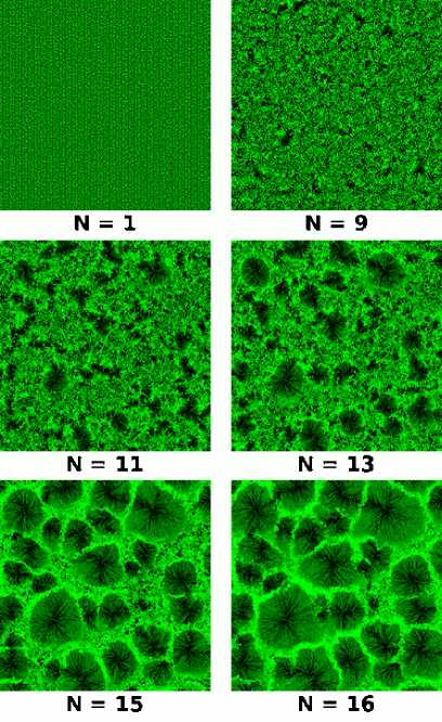
The presented algorithm can be easily implemented and systems up to 300 000 nanotubes can be simulated in reasonable computational time. As observable from the time-sequence in Figure 4, the cellular patterns are formed after nucleation of voids in the spring-block network (time step ). A preliminary void is enlarged by the tensioned springs (time step ) until the top of micropillars arrange in a final and stable cellular structure (time step ). The obtained dynamics resembles the pattern formation mechanism known from experimental in-situ observations [9].
Furthermore, the effect of nanotube density on final patterns is computationally investigated. Simulations with the same parameter set are preformed for systems initialized with different lattice constants . By this, the space filling of the micropillar system
| (5) |
is varied. Here, it has to be noted that the micropillar density and implicitly the micropillar lattice constant are linearly connected to the real nanotube density and the nanotube lattice constant , respectively. If a micropillar is composed by nanotubes, then by simple geometrical calculations it can be shown that
| (6) |
where denotes the radius of a nanotube.
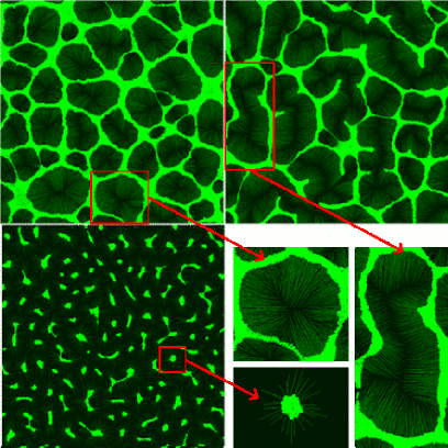
In Figure 5 three different type of simulated structures are presented. For high space filling corresponding to lattice constant polygonal cellular structures are obtained similar to those on the left hand side of Figure 1. As one can observe on the magnified cell image, at the center there is a clean area formed by radially outgoing micropillars. For intermediate space filling which corresponds to a lattice constant the micropillars self-organize into elongated cellular structures. The obtained structures are in qualitative agreement with the experimental structures presented in the right hand side SEM images of Figure 1. When interpreting the image, one has to take into account that the length scale of this snapshot is times smaller than the length scale of the previously discussed one. Accordingly, the typical size of the simulated elongated structures is times grater than the typical size of the polygonal structures. For low space filling corresponding to a lattice constant the micropillars form bundled clusters resembling the recent experimental patterns of sequential assembly of self-similar nanotube clusters [22].
Finally our simulations explored also the possibility of designing highly ordered micropatterns in nanobristles. In this sense, an experimental procedure elaborated in the last years [23] has been reconstructed by our spring-block type simulations. The design procedure is based on the experimental observation that low-density regions or vacancies in the bristle play an important role in the pattern cell nucleation process.
As shown in top panels of Figure 6, different kinds of highly ordered micropatterned structures have been created by etching regular vacancies with laser pulses. Capillary self-organization in such systems yields the structures presented on the top panels of Figure 6.
Simulations on micropillar forests with vacancies of radius created on rectangular and triangular lattice have been performed. The results are shown on bottom panels of Figure 6. In agreement with experimental findings, our spring-block simulation results suggest that various micropatterns may be designed by proper preparation of the initial nanobristle taking into account that the wall of a polygon shaped cell forms approximately at the vertical bisector of two adjacent vacancies.
In conclusion, a simple mechanical, spring-block type model has been proposed here to model capillarity driven self-organization of nanobristles. The 3D problem has been mapped to a 2D model that works at the mesoscopic micropillar level incorporating real interactions known from earlier experimental findings. Our computer simulations evidenced the role of capillary and electrostatic forces in forming the self-organized nanostructures. The dynamics leading to pattern formation has been also revealed. By using the same model parameters with different nanotube densities three qualitatively different types of patterns were reproduced. Moreover, the possibility of designing highly ordered nanostructures has also been explored.
Acknowledgement
This work was supported by CNCSIS-UEFISCSU, project number PN II-IDEI 2369/2008. One of the authors (E-ÁH) was partly funded by a scholarship from the Heidelberg Graduate School of Mathematical and Computational Methods for the Sciences, University of Heidelberg, Germany, which is funded by the German Excellence Initiative (GSC 220).
References
- [1] M. Rieth, Nano-Engineering in Science and Technology: An Introduction to the World of Nano-Design (Series on the Foundations of Natural Science and Technology), World Scientific Publishing Co., Inc., New York, 2003.
- [2] M. Adachi, D. J. Lockwood (Eds.), Self-Organized Nanoscale Materials, Springer, New York, 2006.
- [3] Ch. L. Haynes, R.P. van Duyne, J. Phys. Chem. B 105 (2001) 5599.
- [4] A.A. Chabanov, Y.Jun, D.J. Norris, Appl. Phys. Lett. 84 (2004) 3573.
- [5] F. Járai-Szabó, Z. Néda, S. Aştilean, C. Farcau, A. Kuttesch, Eur. Phys. J. E, 23 (2007) 153.
- [6] F. Ding, K. Jiao, Y. Lin, B. I. Yakobson, Nano Lett. 7 (2007) 681.
- [7] D. P. Young, et al., J. Appl. Phys. 103 (2008) 053503.
- [8] E. R. Meshot, et al., ACS Nano 3 (2009) 2477.
- [9] N. Chakrapani, et al., Proc. Nat. Acad. Sci. 101 (2004) 4009.
- [10] M.F.L. De Volder, D.O. Vidaud, E.R. Meshot, S. Tawfick, A.J. Hart, Microelectron. Eng., 87 (2010) 1233.
- [11] R. Burridge, L. Knopoff, Bull. Seism. Soc. Am. 57 (1967) 341.
- [12] P. Bak, How Nature Works: The science of Self-Organized Criticality, Copernicus, New York, 1996.
- [13] J. V. Andersen, Y. Bréchet and H. J. Jensen, Europhys. Lett. 26 (1994) 13.
- [14] K. Kovács, Y. Brechet, Z. Néda, Modelling Simul. Mater. Sci. Eng. 13 (2005) 1341.
- [15] K.-t. Leung, Z. Néda, Phys. Rev. Lett. 85 (2000) 662.
- [16] F. Járai-Szabó, S. Aştilean, Z. Néda, Chem. Phys. Lett. 408 (2005) 241.
- [17] C. D. Dushkin, P. A. Kralchevsky, H. Yoshimura, K. Nagayama, Phys. Rev. Lett. 75 (1995) 3454.
- [18] P. A. Kralchevsky, et al., J. Colloid Interface Sci. 155 (1993) 420.
- [19] G. Kaptay, J. Mat. Sci. 40 (2005) 2125.
- [20] P. C. Hiemenz, R. Rajagopalan, Principles of Colloid and Surface Chemistry, Marcel Dekker, New York, 1997.
- [21] S. Neukirch, B. Roman, B. de Gaudemaris and J. Bico, J. Mech. Phys. Solids 55 (2007) 1212.
- [22] B. Pokroy, S. H. Kang, L. Mahadevan, J. Aizenberg, Science 323 (2009) 237.
- [23] H. Liu, S. Li, J. Zhai, H. Li, Q. Zheng, L. Jiang, D. Zhu, Angew. Chem. Int. Ed. 43 (2004) 1146.