Optomechanical coupling in a two-dimensional photonic crystal defect cavity
Abstract
Periodically structured materials can sustain both optical and mechanical modes. Here we investigate and observe experimentally the optomechanical properties of a conventional two-dimensional suspended photonic crystal defect cavity with a mode volume of . Two families of mechanical modes are observed: flexural modes, associated to the motion of the whole suspended membrane, and localized modes with frequencies in the GHz regime corresponding to localized phonons in the optical defect cavity of diffraction-limited size. We demonstrate direct measurements of the optomechanical vacuum coupling rate using a frequency calibration technique. The highest measured values exceed 250 kHz, demonstrating strong coupling of optical and mechanical modes in such structures.
pacs:
42.70.Qs, 43.40.DxCavity optomechanics Kippenberg and Vahala (2008); *Marquardt2009; *Favero2009 exploits the coupling of mechanical oscillators to the light field via radiation pressure. On the applied side, such coupling may be used to enable novel radiation pressure driven clocks Kippenberg et al. (2005); *Carmon2005, make highly sensitive displacement sensors, tunable optical filters Rosenberg et al. (2009); *Wiederhecker2009, delay lines Safavi-Naeini and Painter (2010) or enable photon storage on a chip Weis et al. ; Chang et al. (2010). On a fundamental level, such systems can be exploited for demonstrating that nano- and micromechanical oscillators can exhibit quantum mechanical behavior Schwab and Roukes (2005). It has been shown experimentally that it is possible to cool a mechanical oscillator intrinsically via radiation pressure dynamical backaction Arcizet et al. (2006); *Gigan2006; *Schliesser2006. In order to reach the ground state of mechanical motion and enable manipulation in the quantum regime, one approach consists in down-sizing the oscillator, thus shifting the quantum-classical transition towards higher temperatures. Among various sub-micron optomechanical systems presently investigated Thompson et al. (2008); *Anetsberger2009; *Li2008, suspended membranes containing a photonic crystal cavity offer strong light confinement in diffraction-limited volumes and are therefore natural candidates for achieving strong optomechanical coupling. Recently, optomechanical coupling in 1D photonic crystal systems Foresi et al. (1997) has been observed in patterned single Eichenfield et al. (2009a) and dual nanobeams (zipper cavities) Eichenfield et al. (2009b, a). It would be highly desirable to extend such optomechanical coupling to 2D systems, notably photonic crystal defect cavities. Such cavities offer the strong light confinement possible (i.e. small mode volume), high quality factor (Q) Akahane et al. (2003) and have been used for studying cavity QED using quantum dots Yoshie et al. (2004) or for realizing nanolasers Painter et al. (1999); Strauf et al. (2006). Recently, a 2D optomechanical photonic crystal slot cavity has been reported Safavi-Naeini et al. (2010). While mechanical displacement due to strong radiation force generated by band-edge modes in bilayer photonic crystal slabs has been reported as well Roh et al. (2010), to date optomechanical coupling of the 2D conventional defect cavity has not been studied.
In this paper, we demonstrate optomechanical coupling using a photonic crystal defect (L3) cavity. We provide a direct and robust experimental determination of the vacuum optomechanical coupling rate Gorodetsky et al. (2010) using frequency modulation, showing a particularly strong coupling for the localized mechanical modes, which may also be coupled to quantum dots in future studies Wilson-Rae et al. (2004).
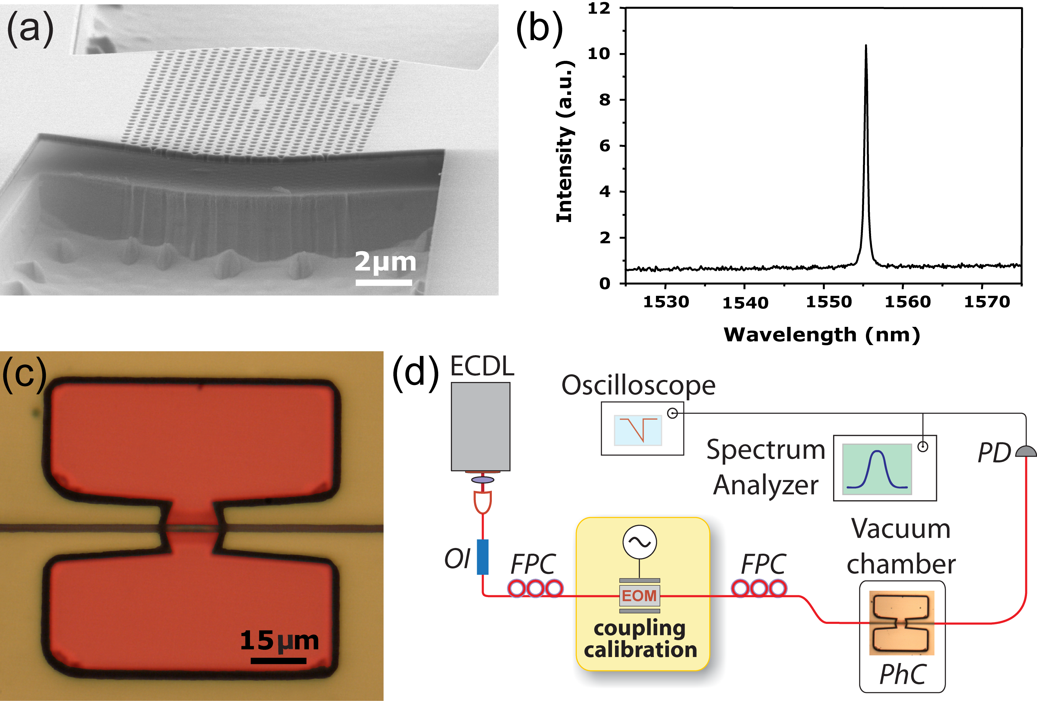
The optomechanical device under study consists of a 262-nm thick InP suspended
membrane containing a two-dimensional photonic crystal defect cavity shown in
Figure 1(a). The cavity, following the design proposed in
Akahane et al. (2003), contains three missing holes in a line of a perfect
triangular lattice of holes with a lattice constant of nm and a radius
nm. At both edges of the cavity the holes are displaced outwards by
, in order to obtain high optical quality factors. The cavity is
fabricated using electron beam lithography, inductively coupled plasma etching
Talneau et al. (2008), and wet etching. The cavity incorporates a single layer of
self-assembled InAsP quantum dots Michon et al. (2008) at its vertical center
plane for cavity characterization. The whole structure is grown by metalo-organic chemical vapor
deposition. The quantum dot density is 109
cm-2, and their spontaneous emission is centered around 1560 nm at 300 K
with an inhomogeneous broadening of about 150 nm. The presence of the dots
inside the cavity allows to identify the spectral properties of the
fundamental optical mode of the cavity by photoluminescence measurements
Hostein et al. (2010), as shown in Figure 1(b). The resonance wavelength
of the fundamental mode is centered around 1555 nm and the cold-cavity quality
factor is measured to be (cavity linewidth is ). The suspended photonic crystal membrane lies on top of a 10 m high mesa
structure (see Fig. 1(a)). The mesa structure is processed to enable
positioning of a tapered optical fiber in the evanescent field of the cavity,
while precluding any interaction with the nearby substrate. The shape of the
membrane resembles a Bezier curve, which was chosen to increase
optomechanical coupling to the flexural modes.
The setup used in the experiment is depicted in Figure 1(d). An external-cavity diode laser is used for the readout of the mechanical motion. Coupling to the optical modes of the suspended membrane is achieved with the optical fiber-taper technique Cai et al. (2000). Piezoelectric actuators enable an accurate positioning allowing to optimize the gap between the fiber-taper and the defect cavity, and thus to increase evanescent coupling. Despite careful reduction of the taper-cavity gap, only a small fraction of the light can be coupled into the defect cavity, typically not exceeding 10 of the incoming laser power. The cavity-fiber system is kept in a vacuum chamber with a pressure below 1 mbar. Laser light coupled inside the photonic crystal cavity leads to local heating, which induces a thermal effect arising from the temperature dependent refractive index Carmon et al. (2004). As ( is the temperature) for InP Martin et al. (1995), the region detuned to the blue side of the resonance allows thermal passive locking Carmon et al. (2004). In our experiments the laser frequency is chosen to correspond to the blue-detuned side of the fringe of the optical mode requiring no further locking. Mechanical motion of the membrane is imprinted on the transmitted optical intensity through modulation of the internal cavity field. An electro-optical modulator is used for frequency modulation to determine the optomechanical coupling rate. The transmitted signal is detected by a fast receiver and the electrical signal is analyzed with an oscilloscope as well as an electronic spectrum analyzer, which is used for the spectral analysis.

For a launched laser power of 1.3 mW more than 20 mechanical modes are observed in the frequency range between 10 MHz and 1 GHz. These modes can be separated into two mode families. The first family consists of flexural modes present in the low-frequency range (below 200 MHz), whereas the second family consists of localized modes. Flexural modes, whose spectrum is shown in Figure 2(a), correspond to the movement of the whole membrane. In order to identify the various modes, we modeled the mechanical properties of the photonic crystal slab structure by finite element modeling (COMSOL Multiphysics). Realistic geometry parameters were taken into account, including the under-etching of the mesa structures between which the membrane is suspended. A good agreement between measurements and modeling is obtained using a Young modulus of 20 GPa (slightly smaller than usual values observed in bulk InP materials iof attributed to the perforation for the photonic crystal). Figure 2(b) shows the displacement patterns of the first eight modes as well as a prominent mode around 150 MHz.
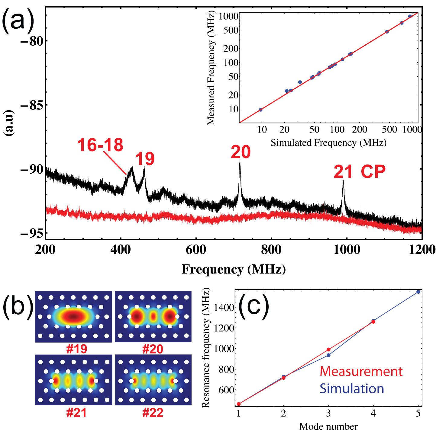
Localized modes, shown in Figure 3, correspond to mechanical displacement of the membrane localized in the cavity core of the defect. We were able to resolve the fundamental localized mode at 0.46 GHz as well as the three higher mode orders (at 0.72 GHz, 0.99 GHz and 1.26 GHz). The inset of Figure 3(a) compares the simulated against the measured resonance frequencies of the mechanical modes that could be assigned, revealing excellent agreement both for flexural and localized modes. The progression of the resonance frequency of the localized modes versus mode number is shown in Figure 3(c) and follows a linear behavior with mode number.
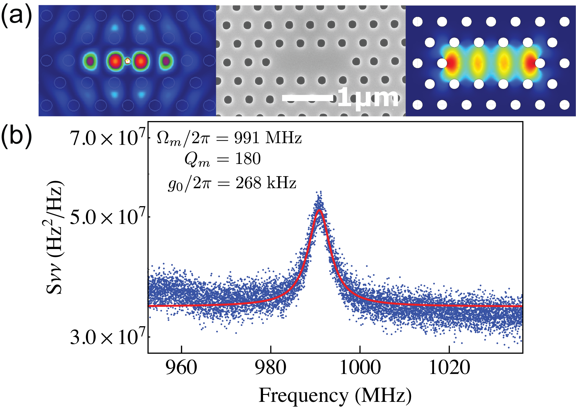
Importantly, localized mechanical modes coincide spatially fully with the optical defect cavity mode. Therefore, the photonic crystal not only offers strong optical confinement, but simultaneously ultra-high phonon confinement. We note that the localization occurs in the absence of a phononic band gap Maldovan and Thomas (2006). Due to the co-localization of the optical and mechanical mode within the defect cavity, strong optomechanical coupling is expected. This is visualized in Figure 4(a), where the results of the mechanical FEM simulation for the third order localized mode are compared with the spatial distribution of the electromagnetic field of the optical defect mode, which was obtained through a finite difference time-domain (FDTD) simulation. The high overlap of the mechanical displacement with the distribution of electromagnetic energy promises strong optomechanical coupling. In a second experiment we determined the coupling rate for various flexural modes and the second and third order localized modes.
Usually, the optomechanical coupling strength is determined by two parameters - the optomechanical coupling parameter , with being the resonance frequency of the optical resonator and denoting the displacement of the mechanical oscillator, and the effective mass Gillespie and Raab (1995); *Pinard1999 of the mechanical mode. The necessity of introducing the effective mass routinely arises from the arbitrary definition of , which often cannot be consistent with the displacement pattern of different mechanical modes of the system. Particularly for photonic crystals it is difficult to define an unambiguous displacement direction of a mechanical mode. One attempt to circumvent this problem is to introduce an effective length determined by a perturbative expression of the overlap of mechanical displacement and the electromagnetic field distribution Eichenfield et al. (2009b, a). Recently, it was suggested that the vacuum optomechanical coupling rate would be a more proper quantity for optomechanical systems Gorodetsky et al. (2010); Safavi-Naeini and Painter (2010). In analogy to cavity Quantum Electrodynamics (cQED), is defined as , with being the zero-point-fluctuations of the mechanical oscillator ( indicates the reduced Planck constant and the mechanical resonance frequency). As all relevant optomechanical parameters can be derived through knowledge of , acquiring its value would make the determination of and redundant. As described in Gorodetsky et al. (2010), the value can be determined experimentally via
| (1) |
with being the average phonon occupancy of the mechanical mode, being the mechanical damping rate and being the frequency spectral density of cavity frequency noise evaluated at the mechanical resonance frequency. For high phonon occupancy one can approximate , with as Boltzmann’s constant. can be experimentally determined by a frequency modulation technique Schliesser et al. (2008a).
We performed a measurement of the cavity frequency noise by applying a known phase modulation to the laser using an LiNbO3 electro-optical modulator (cf. Figure 1). The incoming laser power was reduced to 0.9 mW. To make sure that the mechanical modes were not driven thermally, the laser frequency was slightly detuned from the side of the fringe in both directions just before the experiment. With no change in the resonance frequency of the mechanical mode occurring, we inferred that the mechanical modes were only driven by thermal Brownian motion (=300 K). The modulation frequency was chosen to be close to the resonance frequency of the mechanical mode to be calibrated. The measurement also allows calibration of the frequency noise produced by the mechanical mode. A detailed account of the calibration method is given in SI . A calibrated frequency noise spectrum for the fundamental flexural mode is shown in the inset of Figure 2(a), and the optomechanical vacuum coupling rate was determined to be . The mechanical quality factor for this mode is being the highest for all flexural modes. The coupling rate for the flexural modes increases with the mode number up to several kHz. The optomechanical coupling for the localized mechanical modes was determined to be () and () for the second and third order, respectively. A calibrated frequency noise spectrum for third order localized mode is shown in Figure 4(b). The high values of give a definite experimental proof of the high optomechanical coupling between a photonic crystal defect cavity and a localized mechanical mode. These coupling values are two orders of magnitudes higher than measured in whispering gallery mode toroidal resonators Schliesser et al. (2008b) and doubly-clamped strained silicon nitride beams in the near-field of a silica toroidal resonator Anetsberger et al. (2009), both of which are ca. . Moreover, the measured values are as high as the recently reported coupling of a flexural mode to a photonic crystal slot cavity Safavi-Naeini and Painter (2010). The values of which could be unambiguously obtained are specified in Table 1.
The calibration technique used has the clear advantage that it allows to determine for any mechanical mode from the mere knowledge of its mechanical linewidth and the mechanical mode occupancy. The method does not require knowledge about the optical linewidth, the specific transduction mechanism of the signal through the optical cavity, the spatial distribution of electromagnetic energy or the displacement pattern of the mechanical mode. Thus the method is particularly suitable for optomechanical calibration in photonic crystals due to the frequently complex spatial distribution of both mechanical and optical modes. Moreover, the present planar architecture can be used for photon-phonon conversion experiments Safavi-Naeini and Painter (2010).
| Mode | Measured frequency | Measured vacuum |
|---|---|---|
| index | (MHz) | coupling rate (kHz) |
| 1 | 9.54 | 0.23 |
| 2 | 24.45 | 0.67 |
| 5 | 46.87 | 2.26 |
| 8 | 59.83 | 7.26 |
| 20 | 716 | 199 |
| 21 | 991 | 268 |
In conclusion, we demonstrated optomechanical coupling in a two-dimensional III-V photonic crystal defect cavity. We observed both flexural as well as localized mechanical modes. Furthermore, we provide direct measurements of the vacuum optomechanical coupling rate in a photonic crystal and measure for the first time the coupling of a localized photonic crystal defect mode with a localized 2D mechanical mode. Coupling rates for the localized modes exceed 250 kHz and are two orders of magnitude larger than in conventional optomechanical systems. By integrating a single quantum dot in the defect cavity, a variety of experiments can be envisioned such as laser cooling Wilson-Rae et al. (2004) and coupling of a quantum mechanical oscillator to an artificial atom, once the ground state of the mechanical oscillator is reached.
Funding for this work was provided by European NanoSci-ERA project NanoEPR,
through QNEMS and MINOS by the FP7, the NCCR Quantum Photonics, the SNF and through an ERC Starting Grant SiMP.
References
- Kippenberg and Vahala (2008) T. J. Kippenberg and K. J. Vahala, Science 321, 1172 (2008).
- Marquardt and Girvin (2009) F. Marquardt and S. M. Girvin, Physics 2, 40 (2009).
- Favero and Karrai (2009) I. Favero and K. Karrai, Nature Photon. 3, 201 (2009).
- Kippenberg et al. (2005) T. J. Kippenberg, et al., Phys. Rev. Lett. 95, 033901 (2005).
- Carmon et al. (2005) T. Carmon, et al., Phys. Rev. Lett. 94, 223902 (2005).
- Rosenberg et al. (2009) J. Rosenberg, et al., Nature Photon. 3, 478 (2009).
- Wiederhecker et al. (2009) G. S. Wiederhecker, et al., Nature (London) 462, 633 (2009).
- Safavi-Naeini and Painter (2010) A. H. Safavi-Naeini and O. Painter, arXiv:1009.3529 (2010).
- (9) S. Weis, et al., Science doi:10.1126/science.1195596.
- Chang et al. (2010) D. Chang, et al., arXiv:1006.3529 (2010).
- Schwab and Roukes (2005) K. Schwab and M. Roukes, Phys. Today 58, 36 (2005).
- Arcizet et al. (2006) O. Arcizet, et al., Nature (London) 444, 71 (2006).
- Gigan et al. (2006) S. Gigan, et al., Nature (London) 444, 67 (2006).
- Schliesser et al. (2006) A. Schliesser, et al., Phys. Rev. Lett. 97, 243905 (2006).
- Thompson et al. (2008) J. D. Thompson, et al., Nature (London) 452 (2008).
- Anetsberger et al. (2009) G. Anetsberger, et al., Nature Phys. 5, 909 (2009).
- Li et al. (2008) M. Li, et al., Nature (London) 456, 480 (2008).
- Foresi et al. (1997) J. Foresi, et al., Nature (London) 390, 143 (1997).
- Eichenfield et al. (2009a) M. Eichenfield, et al., Nature (London) 462, 78 (2009a).
- Eichenfield et al. (2009b) M. Eichenfield, et al., Nature (London) 459, 550 (2009b).
- Eichenfield et al. (2009a) M. Eichenfield, et al., Opt. Express 17, 20078 (2009a).
- Akahane et al. (2003) Y. Akahane, et al., Nature (London) 425, 944 (2003).
- Yoshie et al. (2004) T. Yoshie, et al., Nature (London) 432, 200 (2004).
- Painter et al. (1999) O. Painter, et al., Science 284, 1819 (1999).
- Strauf et al. (2006) S. Strauf, et al., Phys. Rev. Lett. 96, 127404 (2006).
- Safavi-Naeini et al. (2010) A. H. Safavi-Naeini, et al., Appl. Phys. Lett. 97, 181106 (2010).
- Roh et al. (2010) Y.-G. Roh, et al., Phys. Rev. B 81, 121101(R) (2010).
- Wilson-Rae et al. (2004) I. Wilson-Rae, P. Zoller, and A. Imamoglu, Phys. Rev. Lett. 92, 075507 (2004).
- Talneau et al. (2008) A. Talneau, et al., Appl. Phys. Lett. 92, 061105 (2008).
- Michon et al. (2008) A. Michon, et al., J. Appl. Phys. 104, 043505 (2008).
- Hostein et al. (2010) R. Hostein, et al., Opt. Lett. 35, 1154 (2010).
- Cai et al. (2000) M. Cai, O. Painter, and K. J. Vahala, Phys. Rev. Lett. 85, 74 (2000).
- Carmon et al. (2004) T. Carmon, L. Yang, and K. Vahala, Opt. Express 12, 4742 (2004).
- Martin et al. (1995) P. Martin, et al., Appl. Phys. Lett. 67, 881 (1995).
- (35) http://www.ioffe.ru/SVA/NSM/Semicond/InP/mechanic.html.
- Maldovan and Thomas (2006) M. Maldovan and E. L. Thomas, Applied Physics Letters 88, 251907 (2006).
- Gillespie and Raab (1995) A. Gillespie and F. Raab, Phys. Rev. D 52, 577 (1995).
- Pinard et al. (1999) M. Pinard, Y. Hadjar, and A. Heidmann, Eur. Phys. J. D 7, 107 (1999).
- Gorodetsky et al. (2010) M. L. Gorodetsky, et al., Opt. Express 18, 23236 (2010).
- Safavi-Naeini and Painter (2010) A. H. Safavi-Naeini and O. Painter, Opt. Express 18, 14926 (2010).
- Schliesser et al. (2008a) A. Schliesser, et al., New J. Phys. 10, 095015 (2008a).
- (42) See SI at [URL by APS] for detailed description.
- Schliesser et al. (2008b) A. Schliesser, et al., Nature Phys. 4, 415 (2008b).
Supplementary information - Optomechanical coupling in a two-dimensional photonic crystal defect cavity
I Determination of the optomechanical vacuum coupling rate
The optomechanical vacuum coupling rate is determined via a frequency modulation technique. An electro-optical modulator (EOM) is used to phase modulate the laser carrier before its coupling into the cavity. The modulated phase of the signal can be written as
| (1) |
with as the radial laser frequency, as the time, as the phase shift factor and as the modulation frequency. The transduced signal from the photonic crystal cavity is detected with a fast receiver and the spectrum is resolved with an electrical spectrum analyzer (ESA). The spectrum exhibits the Lorentzian spectra of the mechanical modes and a calibration peak at resulting from the modulation Schliesser et al. (2008a, b). If the modulation frequency is chosen to be close (a couple of mechanical linewidths) to the resonance frequency of the mechanical mode to be calibrated, can be determined as Gorodetsky et al. (2010)
| (2) |
with as the average phonon occupancy, as the dissipation rate of the mechanical oscillator, RBW as the resolution bandwidth of the ESA, as the double-sided frequency spectral noise density evaluated at the mechanical resonance frequency and as the double-sided frequency noise spectral density evaluated at the modulation frequency. Only the proportion between and is required to be known, and it can be readily obtained from the measured peak power spectral density values of the mechanical and calibration signals. The power spectral density is usually given in dBm in the spectrum of the ESA. The proportion can be found with the following relationship
| (3) |
with being the power at the peak of the calibration signal expressed in dBm and being the power at the peak of the mechanical mode, which is expressed in dBm as well.
The frequency modulation technique can be also used to calibrate the spectrum in absolute units. This is done by directly determining via Gorodetsky et al. (2010)
| (4) |
By using an equivalent scheme depicted in Equation 3, the spectrum can be calibrated. The calibration holds true as long as the frequencies of the values to be calibrated are close enough to the resonance frequency of the calibration peak. Otherwise, a generalized transduction coefficient needs to be included Gorodetsky et al. (2010).
II Calculation of correction factors for the ESA spectrum
When measuring electrical signals with an ESA, one usually expresses the power detected at a certain frequency in the logarithmic units of dBm. By averaging one obtains an average of the logarithmic power, which is not equal to the logarithmic expression of the averaged power - the value that is of significance in the measurements. The discrepancy is different for random signal, such as background noise and the mechanical spectrum (resulting from thermal motion), and for coherent signals, such as a calibration peak with a large enough signal-to-noise ratio. For random signals it is known Agi that the measured value is about 2.5 dB below the actual one, whereas for truly coherent sources the measured signal corresponds to the real one. For signals that have contributions both from a coherent source and random signals, such as a calibration peak with a rather low signal-to-noise ratio, the correction factor depends on the magnitude of both contributions.
Modern ESAs can often compensate this discrepancy internally, however as this function was not applied during our measurements, we need to use the correction described above. In the following we will derive the general expression for the correction of the measured signal.
A signal arriving on the ESA can be decomposed in its in-phase () and out-of-phase () part. Spectrum analyzers respond to the magnitude of the signal within their RBW passband Agi . The magnitude of a signal (voltage) represented by and is given by
| (5) |
The average power arriving on the detector is given by
| (6) |
where an input impedance of 50 is considered (equations are generally dimensionless in this section) and the brackets imply that the mean value is taken of the expression inside them. In the average mode the ESA averages the logarithmic input signal, thus leading to the following expression for the measured power
| (7) |
The logarithmic value of the actual power of the signal is given by
| (8) |
It should be intuitive that the values for and are not equal, just as the log of the average is not the same as the average of the log.
The mean values given in Equations 6 and 7 can be determined by multiplying the variable being measured with its probability density function (PDF) and integrating over the possible values of the variable. The PDFs of the quadratures and can be assumed to be Gaussian with a certain variance for and for , and a certain offset of the distribution from 0 being for and for . In general, one can assume the variance to be the same for both quadratures, so that . For random signals it holds that , whereas for a coherent signal one has , but .
Using the assumptions stated above, one can write
| (9) |
and
| (10) |
From the Equations 6 and 7 it is obvious that we are interested in the mean values of . This requires one to find the PDFs for this variable from the PDFs of and . This is accomplished by using a general relationship, which links the PDFs of independent random variables to the PDF of some variable . This relationship is given by
| (11) |
where denotes Dirac’s delta function.
Using Equation 11 one can determine the PDF of to be
| (12) |
with as a Bessel function of the first kind.
Using this expressions for the PDF of , one can calculate and by using Equations 6 and 7. For one obtains
| (13) | |||||
and for one obtains
| (14) | |||||
where is an incomplete Gamma function and denotes the natural logarithm.
For random signals we set to 0 obtaining
| (15) | |||||
with as the Euler-Mascheroni constant ().
Finally, we obtain a general expression for the discrepancy between the actual and the measured signal
| (16) |
For the special case of a random signal the final expression reads
| (17) |
The discrepancy in this case is a constant value being approximately and independent of as expected.
For a strongly coherent signal with one obtains . This means that for a strong coherent drive there is no discrepancy between the measured and the real one.
III Experimental Implementation
The phase shift factor can be determined by
| (18) |
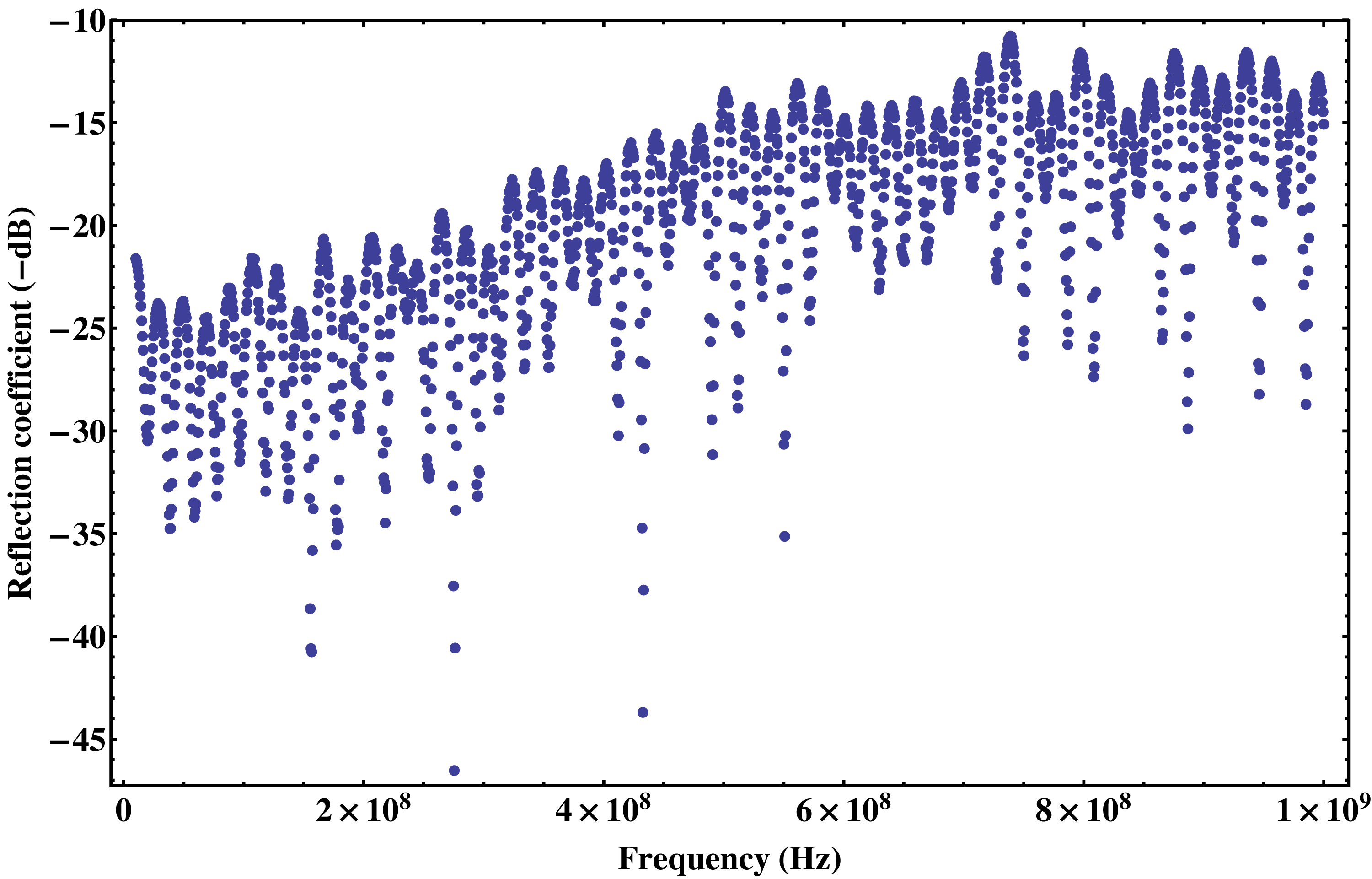
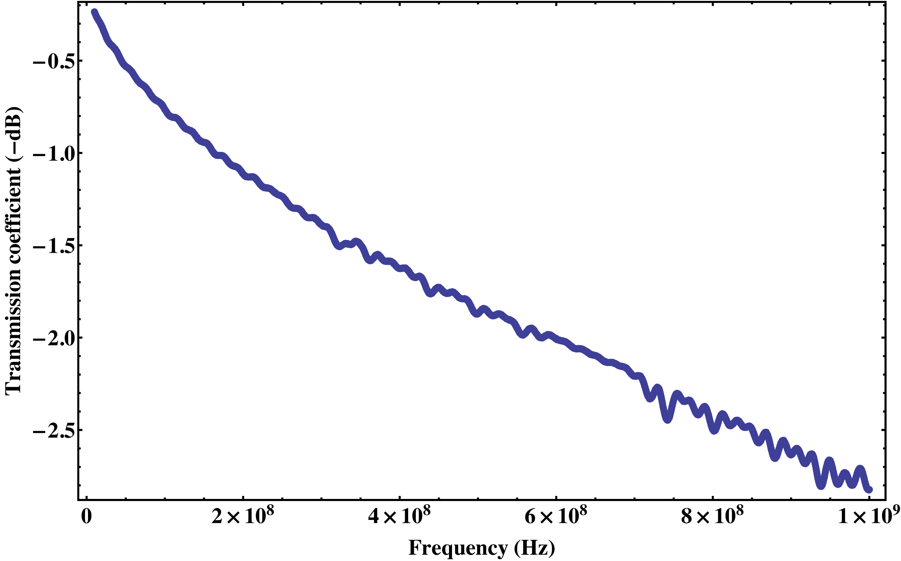
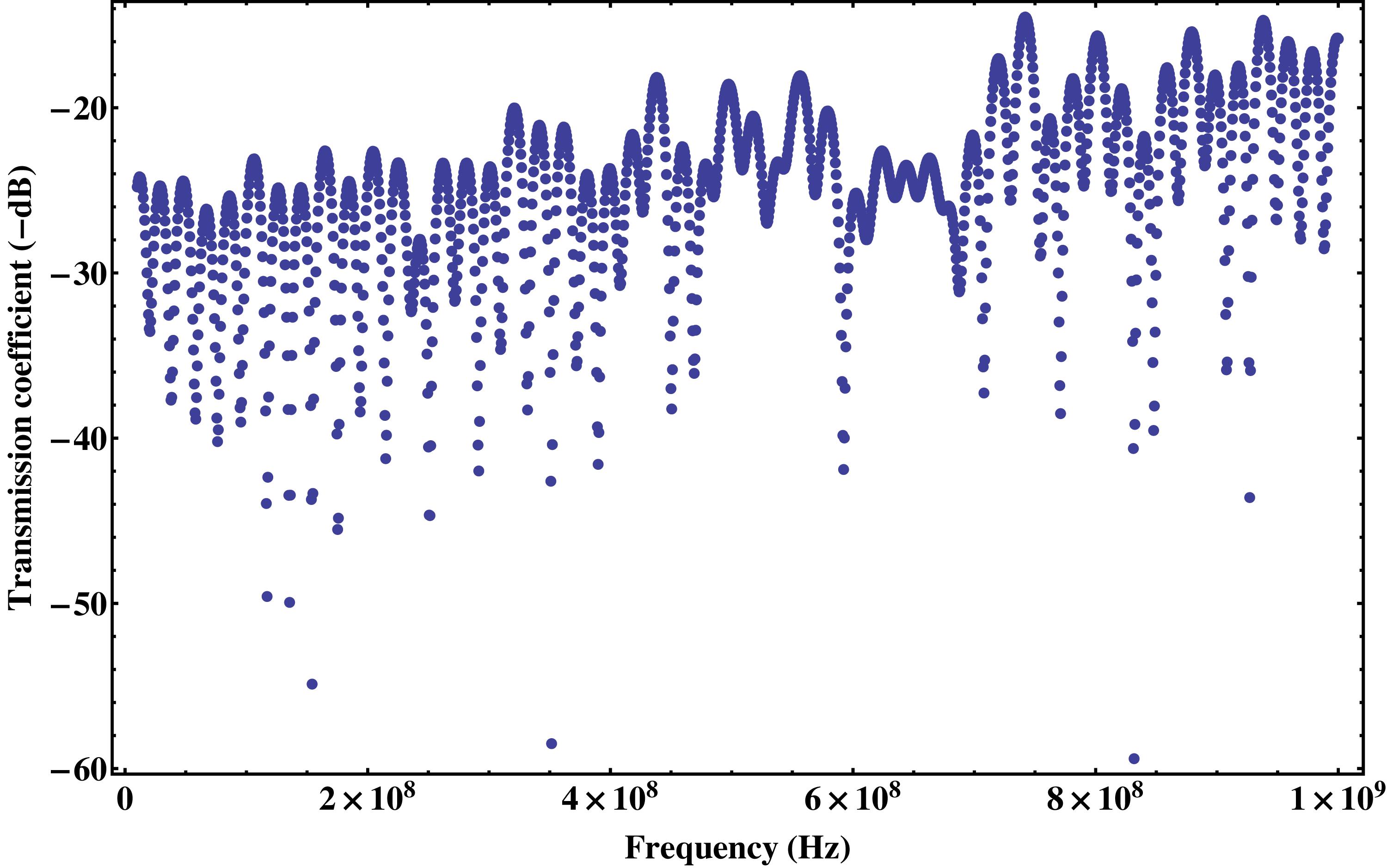
with as the applied voltage, as the voltage needed to induce a phase shift of , as the input power of the signal generator providing the modulation signal and as the impedance between the signal generator and the EOM. To have a quantitavie understanding of the actual voltage applied on the EOM, we directly measured the reflectance of the system consisting of the EOM and the BNC cable linking it to the signal generator. Moreover, we measured transmittance through the BNC cable to account for potential losses. The measurements were performed using a network analyzer. Figure S1 shows the fraction of the reflected power of the combined EOM+cable system as a function of the output frequency of the signal generator. Figure S2 shows the fraction of transmitted power through cable as a function of frequency. It is obvious that for high frequencies the power loss becomes fairly strong, which is due to radiation losses in the BNC cable. This fact is undermined by Figure S2 showing the reflection coefficient through the cable, which is well below the one of the total EOM+cable system.
The factor can be thus determined as
| (19) |
Measurements gave a value of which is consistent with the value provided of the manufacturer of the EOM.
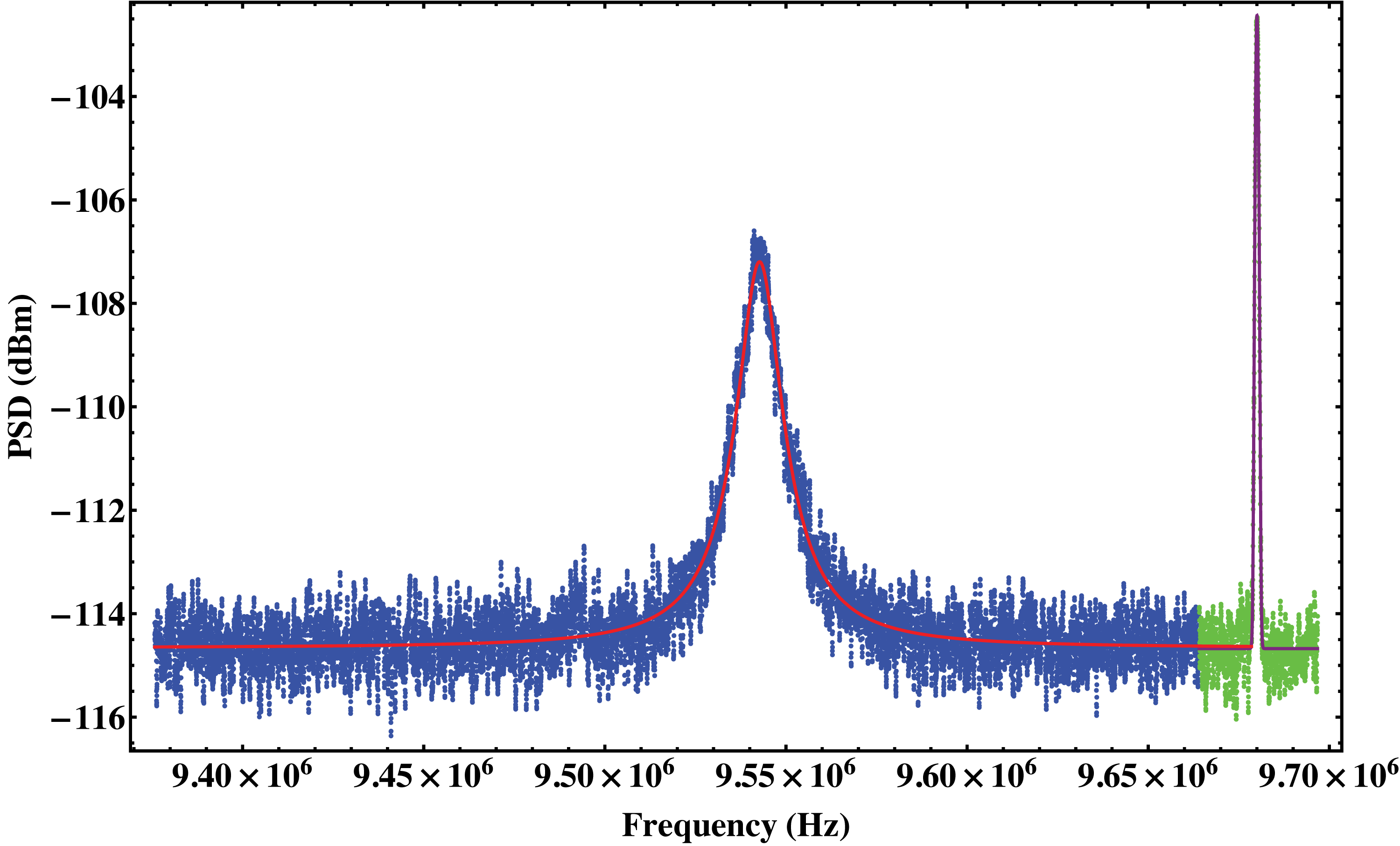
A spectrum of the fundamental flexural mode is shown in Figure S4 together with the calibration peak. As discussed in the previous section, the measured spectrum needs to be readjusted. This is done by first fitting the mechanical with a Lorentzian and the calibration peak with a Gaussian. The noise level is obtained from the baseline of the Lorentzian, and this value is subsequently used to determine the variance as defined in Equations 9 and 10 through use of Equation 15. From the Gaussian fit we obtain the maximum value of the calibration peak. Using this value together with the determined value of , one can numerically solve Equation 14 to obtain . The value of is the corrected maximum value of the calibration peak. The spectrum of the random signals, consisting of the background noise and the mechanical response, is corrected with the constant value given in Equation 17. The corrected values for the maxima of the mechanical spectrum and the calibration peak are used together with , inferred from the Lorentzian fit, to determine as described in Equation 2. By using Equation 4 one can calibrate the spectrum in absolute frequency units.
The values of , that could be unambiguously determined, are summarized in Table S1. The value of without the correction for logarithmic averaging is also stated together with the calculated correction for the calibration peak. The required correction for the calibration peak is fairly small for most measurements due to the large enough signal-to-noise ratio. In those cases the main correction stemmed from the adjustment of the random signals by a constant factor of around 2.5 dBm.
| Mode | (without correction) | Correction factor for the calibration peak | ||
|---|---|---|---|---|
| 1 | MHz | Hz | Hz | 0.000 dBm |
| 2 | MHz | Hz | Hz | 0.004 dBm |
| 3 | MHz | kHz | kHz | 0.007 dBm |
| 4 | MHz | kHz | kHz | 0.000 dBm |
| 5 | MHz | kHz | kHz | 0.045 dBm |
| 6 | MHz | kHz | kHz | 0.322 dBm |
The values of , that could be unambiguously determined, are summarized in Table S1. The value of without the correction for logarithmic averaging is also stated together with the calculated correction for the calibration peak. The required correction for the calibration peak is fairly small for most measurements due to the large enough signal-to-noise ratio. In those cases the main correction stemmed from the adjustment of the random signals by a constant factor of around 2.5 dBm.
References
- Schliesser et al. (2008a) A. Schliesser, G. Anetsberger, R. Rivère, O. Arcizet, and T. J. Kippenberg, New J. Phys. 10, 095015 (2008a).
- Schliesser et al. (2008b) A. Schliesser, R. Rivère, G. Anetsberger, O. Arcizet, and T. J. Kippenberg, Nature Phys. 4, 415 (2008b).
- Gorodetsky et al. (2010) M. L. Gorodetsky, A. Schliesser, G. Anetsberger, S. Deleglise, and T. J. Kippenberg, Opt. Express 18, 23236 (2010).
- (4) Agilent Application Note 1303: Spectrum and Signal Analyzer Measurements and Noise, Agilent Technologies.