Interedge magnetic coupling in transition-metal terminated graphene nanoribbons
Abstract
The magnetic structures and interedge magnetic couplings of Fe, Co and Ni transition-metal terminated graphene nanoribbons with zigzag (ZGNR) and armchair (AGNR) edges are studied by first-principles calculations. Fe-ZGNR is found to show antiferromagnetic (AF) coupling between two edges, while the interedge coupling of Co-ZGNR is ferromagnetic (FM). For Fe-AGNRs and Co-AGNRs, increasing the interedge distance we follow oscillatory transitions from FM to AF coupling with a period of about 3.7 Å. The damped oscillatory behavior indicates a Ruderman-Kittel-Kasuya-Yosida type interedge magnetic coupling and the oscillation period is determined by the critical spanning vector which connects two inequivalent Dirac points in the graphene Brillouin zone. The two edges in Ni-ZGNR are decoupled independent of the ribbon width and Ni-AGNRs are found to be nonmangetic.
pacs:
73.22.Pr, 75.30.Et, 75.75.-cGraphene, a monolayer of carbon atoms packed into a honeycomb lattice, continues to attract immense interest, mostly because of its two-dimensional stability, unique band structure and other unusual physical propertiesGeim:2009 . In particular, cutting graphene along two high-symmetry crystallographic directions produces quasi-one-dimensional periodic strips of graphene with armchair or zigzag edges, usually referred to as graphene nanoribbons (GNRs). The zigzag edge GNR (ZGNR) is theoretically predicted to be magnetic with two spin-polarized edge states, which are ferromagnetically ordered but antiferromagnetically coupled to each other through the graphene backbone Fujita:1996 ; Lee:2005 ; Son:2006 , while the armchair edge GNR (AGNR) is found to be nonmagnetic. The interedge magnetic coupling in ZGNRs has attracted considerable attention Lee:2005 ; Son:2006 ; Pisani:2007 ; Jung:2009 . Antiferromagnetic coupling of the two zigzag edges in ZGNR can be explained in terms of interactions between the magnetic tails of the edge statesLee:2005 , since the C atoms always stand at the opposite sublattices of GNR at the two zigzag edges. The magnitude of the interedge magnetic coupling shows a dependence as a function of the ribbon width Pisani:2007 ; Jung:2009 .
Most of the studies of interedge magnetic coupling on GNRs focus on ribbons with zigzag edges and hydrogen terminations. We have previously reported that metal terminated GNRs can also exhibit magnetics behavior Wang:2010 . Furthermore, GNRs with ferromagnetically coupled edges terminated with transition metals show high degree of spin polarization at the Fermi energy, and thus can be excellent candidate for spintronic applications. The interedge magnetic coupling in Fe terminated ZGNRs has also been studied by Ong et al. Ong:2010 very recently, showing that the coupling is antiferromagnetic and the strength decreases with increasing ribbon width.
For a full understanding of the interedge magnetic coupling in TM-GNR systems, in this paper, we present a first-principles study of zigzag and armchair GNRs terminated with Fe, Co and Ni 3d transition metals, focusing on the width dependence of the magnetic coupling between two edges. Interestingly, the behavior of interedge magnetic coupling is found to differ significantly with different type of metal terminations or ribbon edges. We also find a damped oscillatory behavior of interedge magnetic coupling and the oscillation period is determined by the critical spanning vector which connects two Dirac points in the graphene Brillouin zone.
| a | b | ||||||||||
|---|---|---|---|---|---|---|---|---|---|---|---|
| 10-Fe-ZGNR | 2.18 | 2.76 | 1.86 | 4.10 | 1.63 | 1066.5 | 9.0 | 2.20 | 2.30 | ||
| 10-Co-ZGNR | 2.34 | 2.60 | 1.82 | 4.49 | 1.71 | 724.6 | -2.2 | 1.20 | 1.58 | ||
| 10-Ni-ZGNR | 2.47 | 2.47 | 1.80 | 5.05 | 2.11 | 0.1 | 0.20 | 0.17 | |||
| 17-Fe-AGNR | 2.14 | 2.41 | 1.86 | 3.71 | 1.84 | 911.6 | -4.6 | 2.12 | 2.14 | ||
| 17-Co-AGNR | 2.23 | 2.35 | 1.83 | 3.99 | 2.07 | 363.5 | 4.6 | 1.19 | 1.54 | ||
| 17-Ni-AGNR | 2.24 | 2.32 | 1.81 | 4.52 | 2.49 | 0 | 0 | 0 |
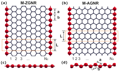
The electronic structure calculations are performed using density functional theory implemented in the plane-wave-basis-set Vienna ab initio simulation package (VASP) VASP:1996 . Each ribbon is simulated within a supercell geometry containing 4 metal atoms at two edges, as shown in Fig. 1. A large vacuum spacing of 15 Å is used between two edges and between two graphene planes to prevent interaction between adjacent images. Projector augmented wave (PAW) potentials with kinetic energy cutoff of 500 eV are employed in all simulations. For the exchange and correlation functional we use the Perdew-Burke-Ernzerh generalized gradient approximation Perdew:1996 . Brillouin-Zone sampling is done on a grid of Monkhorst-Pack Monkhorst:1976 k-points along the periodic direction of the ribbon for ZGNRs and for AGNRs. The Gaussian smearing method is used to treat partial occupancies, and the width of smearing is chosen to be 0.1 eV for geometry relaxations. The geometries are optimized until all forces on all ions fall below the threshold value of 0.01 eV/Å. To obtain accurate magnetic configurations and ensure high accuracy in the calculated total energies of relaxed structures, calculations are conducted using Gaussian smearing of 0.05 eV and PAW pseudopotentials for Fe and Co which treat the 3p semi-core states as valence states.
Two typical structures of metal-terminated GNRs with 8 carbon zigzag chains and 14 carbon dimer lines across the ribbon width are shown in Fig. 1 (a) and (b), respectively. Hereafter we refer to a metal-terminated GNR with dimer lines as a -TM-AGNR and that with zigzag chains as a -TM-ZGNR where TM stands for Fe, Co or Ni. Both edges of the ribbon have the same configuration for each case. We find the lowest-energy structures of the ribbon by structural relaxation calculations for three possible termination configurations: the linear type (), the dimerized linear type ( and ), and the zigzag type (). The calculated ground state structural properties are listed in Table 1 for 10-TM-ZGNRs and 17-TM-AGNRs. The results show that the most favorable structures for all studied TM-ZGNRs are all linear while the TM-AGNRs are all zigzag type mainly because of a relatively smaller length of the AGNR unit cell. The Fe and Co terminations dimerize at the edge of ribbon due to the Peierls distortion Peierls:1955 . Changing the width of the ribbon will have negligible effect on the structure of the edges. The binding energies of the metal atom, defined as , and the formation energy of the metal chain, , are also listed in Table 1. The difference between and represents a direct binding between the TM and carbon atoms at the ribbon edge. It is clearly shown that for all cases the metal atoms bond strongly with edge carbon atoms.
Next we examine the magnetic structures and couplings between the magnetic moments in the ribbon edges. Three states with different spin configurations of the TM terminations are considered: (i) antiferromagnetically ordered spins at each edge of the ribbon, denoted by AFE, (ii) ferromagnetically ordered spins along both edges with the same spin direction, denoted by FM, and (iii) ferromagnetically ordered spins at each edge with the opposite spin directions between the edges, denoted by AF. Total energy calculations are performed to decide the ground states of the magnetic structures.
Except for Ni-AGNR which is found to be nonmagnetic, each ribbon considered shows spin polarized edges with ferromagnetic ordering of the metal atoms at each edge for the lowest-energy state. In Table 1 we show examples of 10-TM-ZGNRs and 17-TM-AGNRs. Besides that the AFE state of Ni-ZGNR is found to be not stable at all, it is clearly shown that AFE state with antiferromagnetically ordered spins at each edge are not favored, with a large energy difference as compared to FM or AF states. Though in the Fe-AGNRs and Co-AGNRs the metal terminations alternatively bond to the opposite sublattices of GNR along each armchair edge, the favorable FM (or AF) state is consistent with the ferromagnetic ordering found in the ground states for Fe, Co and Ni monatomic chains Ataca:2008 . In Fe-ZGNRs and Co-ZGNRs the energetic disadvantage of AFE state is very obvious, and can be explained by the interactions between the magnetic tails of the edge spins Lee:2005 , since the metal atoms always bond to the same sublattices of GNR at each zigzag edges. Generally the magnetic moment of the ribbon comes mostly from the metal atoms and their nearest-neighbor C atoms at the edges, and the edge C atom presents magnetization antiparallel to the nearby metal atom, as shown in Table 1 for ribbons with FM states. In the AF state the moments at two edges have exact the same values but with opposite signs, thus the net magnetic moment of the ribbon is zero.
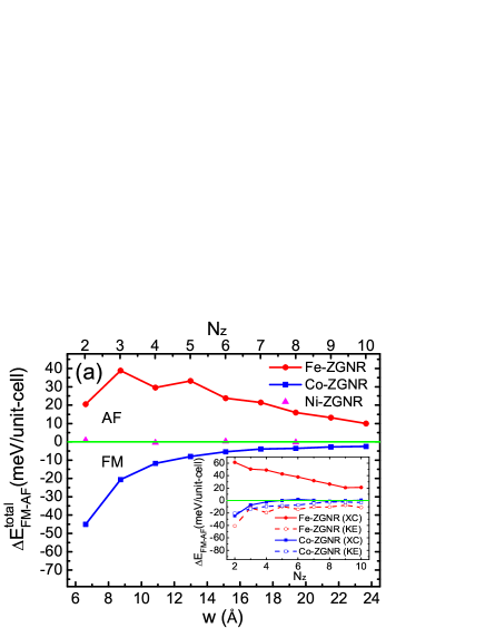
The magnetic order between the two edges for the ground state can be either FM or AF favored depending on the interedge magnetic coupling. Flipping the spin moments of one of the edges will result a total energy change in the system for comparable size of the magnetic moments at the metal terminations. The interedge magnetic interaction strength can be identified by the total energy difference between the FM and AF states. Our calculations show that the ground states of Fe-ZGNRs are always AF, similar to H-ZGNRs and ZGNRs without H-passivation Lee:2005 ; Son:2006 ; Pisani:2007 . The behavior of the as a function of the ribbon width is shown in Fig. 2 (a). For the decreases almost linearly with increasing ribbon widths, in agreement with a recent calculation by Ong et al. Ong:2010 . However, in the case of 2-Fe-ZGNR the is much lower than that of 3-Fe-ZGNR.
Contrary to the case of Fe-ZGNRs, we find that the interedge magnetic coupling of Co-ZGNR with a finite width is always FM, as shown in Fig. 2 (a). The absolute value of difference in total energy also decay as increases. It becomes negligible when the two edges are separated by a large ribbon width. By fitting the variation with , one obtains a decay law close to . However, the almost monotonic width dependence of coupling for Fe-ZGNR and Co-ZGNRs shown in Fig. 2 (a) are only part of the story and will be re-examined later. The smaller amplitude of interedge magnetic interaction in Co-ZGNR at large as compared to Fe-ZGNR is primarily due to the fact that magnetic moments of Co-ZGNRs are more localized localized at the edges Wang:2010 . Inside the Co-ZGNR the magnetic tails of the edge moments decay much faster than Fe-ZGNR, resulting almost zero moments in the inner C atoms of the ribbon. This localization effect is more remarkable in the case of Ni-ZGNRs. The interedge exchange interaction is found to be negligible in Ni-ZGNRs, as the FM and AF states become almost degenerate at even the shortest width with .
The total energy difference between FM and AF states can be separated into non-interaction one-electron (kinetic), Hartree (electrostatic) and exchange-correlation (XC) contributions:
| (1) |
A close inspection of the curves in Fig.2 (a) shows that the XC contribution to the total energy, is clearly responsible for the different type of interedge coupling in Fe-ZGNRs and Co-ZGNRs. For Fe-ZGNRs the is always positive, while in Co-ZGNRs the is negative but become negligible for large interedge distances. A comparison between and indicates that FM coupling always lower the kinetic and electrostatic (KE) parts of the contribution for both Fe-ZGNRs and Co-ZGNRs, especially for ribbons with short interedge distances. However, the two edges of Fe-ZGNR are still AF coupled resulting from a large energy difference from the XC contribution. Take the 2-Fe-ZGNR as an example: the FM coupling lowers the KE contributions to the total energy by 41 meV/unit-cell but at a cost of meV/unit-cell in the XC contribution, resulting a meV/unit-cell for an AF coupling as the ground state.
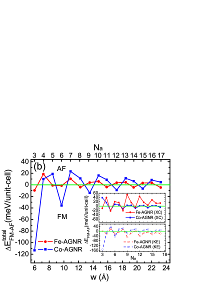
For GNRs with armchair edges terminated by Fe and Co atoms, the interedge coupling between the two edges favor either AFM or FM depending on the ribbon width. The energy difference between the FM and AF states as a function of the ribbon width is plotted in Fig.2 (b). A damped oscillatory behavior, as shown in Fig.2 (b) for both Fe-AGNRs and Co-AGNRs, clearly indicate a Ruderman-Kittel-Kasuya-Yosida (RKKY)-type RKKY interedge exchange. A -Fe-AGNR is FM coupled only if (where m is a positive integer), and a -Co-AGNR is FM only if .
The well-known long-range RKKY interaction between two magnetic impurities in a non-magnetic host material is mediated by the conduction electrons of the host, and the coupling strength can be written as Fischer:1975 ; Yafet:1987
| (2) |
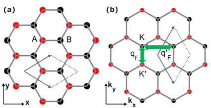
where is the assumed dimensionality, is the distance between two impurities and is the wavevector at the Fermi level. By choosing dimensionality and set as the interedge distance of the ribbon, our results of the total energy difference can be fitted very well using Eq. (2) with a period of about 3.7 Å for both Fe-AGNRs and Co-AGNRs and slightly different phase . This is analogous to the case of the interlayer exchange coupling between ferromagnetic layers separated by nonmangnetic metallic spacer Stiles:1999 , where a two-dimensional range function, , is used to describe the oscillatory behavior of the coupling strength as a function of the spacer thickness . The , which determines the oscillation period, is the critical spanning vector parallel to the interface normal that connects two sheets of the Fermi surface of the spacer at a point where they are parallel to each other. Similarly, here we find that the fitted is exactly the critical spanning vector connecting two inequivalent Dirac points and in the Brillouin zone of graphene in the direction of the metal-AGNR interface (along the armchair edges) normal, which is shown in Fig.3. Another spanning vector , which connects two equivalent Dirac points - or -, determines the oscillation period of the interedge coupling for ZGNRs. However, following the discussion above we get Å which coincides with the interedge lattice spacing in ZGNRs. This clearly explains why the damped oscillatory behavior is not shown in actual width dependence of the for either Fe-ZGNRs or Co-ZGNRs but a monotonic behavior.
The width dependences of the XC and KE contributions to the total energy difference are also shown in Fig.2 (b) for Fe-AGNRs and Co-AGNRs. Both and show similar oscillatory behavior as the with a same period, a phase shift as compared to the curve is found for the KE contribution in Fe-AGNRs, and for the XC contribution in Co-AGNRs. This indicates that the damped oscillatory behavior in the width dependence of is resulting from a competition between different contributions to the total energy.
In summary, we have presented a study of the interedge magnetic coupling of Fe, Co and Ni terminated graphene nanoribbons through first-principles calculations. We find that the ferromagnetic ordering of the metal terminations at each edge of the ribbon is favored for both ZGNRs and AGNRs. Whether the interedge magnetic coupling is ferromagnetic or antiferromagnetic depends to a large extent on the type of metal atoms and edges, as well as the ribbon width. The two edges for Fe-ZGNR are found to be antiferromagnetically coupled while for Co-ZGNR ferromagnetic coupling is favored, and the strength of the interedge exchange interaction decreases as the ribbon width increases. For both Fe-AGNRs and Co-AGNRs the interedge exchange interactions show damped oscillatory behavior as a function of the ribbon width with a period of about 3.7 Å. The interedge magnetic coupling is negligible in Ni-ZGNRs, and Ni-AGNRs are found to be nonmagnetic.
This work was supported by US/DOE/BES/DE-FG02-02ER45995. The authors acknowledge DOE/NERSC and the UF-HPC center and for providing computational resources.
References
- (1) A. K. Geim, Science 324, 1530 (2009).
- (2) M. Fujita, K. Wakabayashi, K. Nakada, and K. Kusakabe, J. Phys. Soc. Jpn. 65, 1920 (1996).
- (3) H. Lee, Y.-W. Son, N. Park, S. Han, and J. Yu, Phys. Rev. B 72, 174431 (2005).
- (4) Y.-W. Son, M. L. Cohen, and S. G. Louie, Phys. Rev. Lett. 97, 216803 (2006).
- (5) L. Pisani, J. A. Chan, B. Montanari, and N. M. Harrison, Phys. Rev. B 75, 064418 (2007).
- (6) J. Jung, T. Pereg-Barnea, and A. H. MacDonald, Phys. Rev. Lett. 102, 227205 (2009).
- (7) Y. Wang, C. Cao, and H.-P. Cheng, Phys. Rev. B 82, 205429 (2010).
- (8) S. V. Ong, R. Roblesa and S. N. Khanna, Chem. Phys. Lett. 492, 127 (2010).
- (9) G. Kresse and J. Furthmüller, Comput. Mat. Sci. 6, 15 (1996).
- (10) J. P. Perdew, K. Burke, and M. Ernzerhof, Phys. Rev. Lett. 77, 3865 (1996).
- (11) H. J. Monkhorst and J. D. Pack, Phys. Rev. B 13, 5188 (1976).
- (12) R. E. Peierls, Quantum theory of solids. Oxford University Press, London (1955).
- (13) C. Ataca, S. Cahangirov, E. Durgun, Y.-R. Jang, and S. Ciraci, Phys. Rev. B 77, 214413 (2008).
- (14) M. A. Ruderman and C. Kittel, Phys. Rev. 96, 99 (1954); T. Kasuya, Prog. Theor. Phys. 16, 45 (1956); K. Yosida, Phys. Rev. 106, 893 (1957).
- (15) B. Fischer, M. W. Klein, Phys. Rev. B 11, 2025 (1975).
- (16) Y. Yafet, Phys. Rev. B 36, 3948 (1987).
- (17) M. D. Stiles, J. Magn. Magn. Mater. 200, 322 (1999).