Broadband Slow Light Metamaterial Based on a Double-Continuum Fano Resonance
Abstract
We propose a concept of a low-symmetry three-dimensional metamaterial exhibiting a Double-Continuum Fano (DCF) optical resonance. Such metamaterial is described as a birefringent medium supporting a discrete “dark” electromagnetic state weakly coupled to the continua of two nondegenerate “bright” bands of orthogonal polarizations. It is demonstrated that light propagation through such DCF metamaterial can be slowed down over a broad frequency range when the medium parameters (e.g. frequency of the “dark” mode) are adiabatically changed along the optical path. Using a specific metamaterial implementation, we demonstrate that the DCF approach to slow light (SL) is superior to that of the EIT because it enables spectrally uniform group velocity and transmission coefficient.
pacs:
78.20.Ci 42.25.Bs 78.67.Pt 78.67.Pt 41.20.JbThe ability to slow down light to low group velocities compared with the vacuum light speed while maintaining high coupling efficiency Hau et al. (1999) is one of the most dramatic manifestations of controlled light manipulation in optics. Apart from its fundamental significance, it has long-reaching technological applications Krauss (2008), including enhanced nonlinear effects due to the energy density compression by as much as ; pulse delay and storage for optical information processing Zhu et al. (2007); optical switching, and quantum optics. Most approaches to obtaining SL rely on the phenomenon of Electromagnetically Induced Transparency (EIT) Harris (1997). EIT and its analogs have been demonstrated in several media, including cold Hau et al. (1999), warm atomic gases Budker et al. (1999), and even plasmas Shvets and Wurtele (2002); Avitzour and Shvets (2008).
More recently, in response to the emerging applications such as bio-sensing, an increasing attention has shifted towards obtaining EIT using electromagnetic metamaterials Zhang et al. (2008); Papasimakis et al. (2008); Liu et al. (2009). Metamaterials enable engineering electromagnetic resonances with almost arbitrary frequencies and spatial symmetries. For example, the EIT phenomenon has been emulated in metamaterials Zhang et al. (2008); Papasimakis et al. (2008); Liu et al. (2009) possessing two types of resonances: a “dark” one, which is not directly coupled to the incident electromagnetic field, and a “bright” one, which is strongly coupled to the incident field. If the respective frequencies of these resonances, and , are very close to each other, they can become strongly coupled by a slight break of the metamaterial’s symmetry.
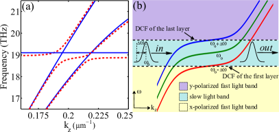
The most serious limitation of the EIT-based SL (EIT-SL) stems from the desirability of achieving the SL over a broad spectral range, especially for optical buffering of ultra-short pulses. Increasing coupling between the bright and dark resonances broadens the spectral range, yet comes at the expense of increasing both the group velocity and group-velocity dispersion . Qualitatively, the bandwidth limitation of the EIT-SL arises because the flatness of the EIT transmission band (which is necessary for small , where and are, respectively, the frequency and the wavenumber of the propagating radiation) originates from the finite spectral width of the EIT band. Therefore, only the light inside the bandwidth can be slowed down. Using metamaterials with spatially-dependent along the propagation direction cannot increase the total propagation bandwidth of the EIT-SL because the EIT band is surrounded by the stop bands as illustrated below. Therefore, a natural solution to the bandwidth problem is to design a metamaterial supporting a propagating mode which is spectrally broad, yet possesses a “flat” segment with , as is schematically shown in Fig. 1.
In this Letter we propose a new approach to producing SL which relies on the phenomenon of Double-Continuum Fano (DCF) Fano (1961) optical resonance: coupling of a single discreet state (“dark” mode) to the two sets of continuum states (two propagating modes of different polarization states). If the frequency of the “dark” mode is embedded in the frequency continua of the propagating modes, then a simple symmetry breaking couples all three modes. The result of such coupling is a very unusual propagation band [see Fig. 1(a)] which fulfills the above requirement for broadband SL applications by continuing from one propagating mode to another, with the SL region in between. We demonstrate that multiple layers of such DCF metamaterial with adiabatically changing frequency of the “dark” mode [as schematically explained in Fig. 1(b)] give rise to broadband SL with spectrally uniform group velocity and transmission. Unlike the more commonly known single-continuum Fano resonance Miroshnichenko et al. (2010); Luk yanchuk et al. (2010) that can be observed with highly symmetric molecules possessing at least one reflection mirror symmetry, DCF resonance requires low spatial symmetry molecules that are not reflection-symmetric with respect to any plane passing through the direction of light propagation.
Before introducing a specific metamaterial realization, we consider a very general case of a DCF medium comprised of anisotropic molecules containing two “bright” transitions (characterized by the oscillator strengths and , respectively, coupled to the two light polarizations) and one “dark” transition (characterized by the oscillator strength and decoupled from the light). The equations for the coupled oscillator strengths , , and excited by the light with the electric field components and are:
| (1) |
where are the resonant frequencies of the transitions and are the coupling coefficients between them. and are coupled to external fields through the coupling constants and , where is a constant with a dimension of , and are the depolarization factors such that the dipole moment normalized to one molecule’s volume is . On the other hand, the dark state cannot be directly excited by the electric field, nor does it directly contribute to the polarizability of the medium, thereby playing the role of the discrete Fano state.
Solving for and in the form of (where =,), we can construct the dielectric permittivity tensor , where , and diag, where is the molecular density. The effective polarizability of the DCF medium is given by:
| (2) |
where is the determinant of the matrix formed by the l.h.s of Eq. (1), and . Photonic band structure (PBS) is analytically calculated from the eigenvalue equation for : , which directly follows from the Maxwell’s equations.
Unlike the EIT case where the dark mode’s frequency needs to be matched to that of the -dipole resonance Zhang et al. (2008); Liu et al. (2009), the DCF occurs under the following conditions: (i) , and (ii) at least 2 of the 3 coupling constants (, and ) are non-vanishing. Without significant loss of generality, and with an eye on the specific metamaterial implementation (see schematic in Fig. 2), we have neglected the direct coupling between and . Finite values of the ’s is the consequence of the reduced spatial symmetry of the anisotropic molecule. For example, would be either accidental, or due to the high spatial symmetry of the molecule (e.g., mirror symmetry). Figure 1(a) shows the PBS in the DCF medium (dashed line) calculated from the analytical model using the following parameters: THz, =50,0,50 THz2, =1, =1.65, =529 THz2, and =.
The unusual PBS in the DCF medium can be understood through its evolution from that in the medium comprised of the symmetric molecules (, ) [solid lines in Fig. 1(a)]. First, the coupling hybridizes the -dipole and the quadrupole resonances and creates an avoided crossing between the -polarized propagation band and the discrete “dark” mode. The second avoided crossing between the -polarized propagation band and the discrete “dark” mode occurs owing to .
Thus, the DCF medium comprised of the low-symmetry molecules supports a propagation band that smoothly connects the two orthogonally polarized continua by passing through the SL region near the “dark” mode’s frequency . Such PBS has the following advantages over that in the EIT medium: (i) the dark mode frequency has more tunability because it is only required to be embedded inside the continuous bands, and (ii) there are no bandgaps on either side of the SL region. These features of the SL band are necessary for realizing the broadband SL using the approach of adiabatically-varying material parameters [specifically, ] schematically shown in Fig. 1(b).
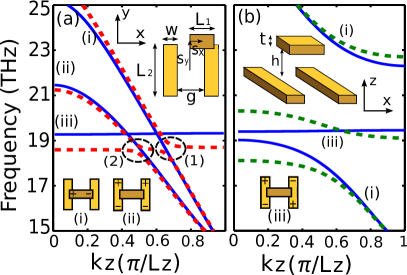
Both DCF and EIT metamaterials supporting the propagation of slow light can be implemented using a three-dimensional periodic arrangement of the unit cells comprised of three metallic antennas. Such unit cell shown in Fig. 2 consists of vertical and horizontal metallic antennas embedded in a dielectric medium with . It is reminiscent of the ones used for single-layer EIT metamaterials Zhang et al. (2008); Liu et al. (2009), except that both and are allowed to be non-vanishing, thereby dispensing with all reflection symmetries of the unit cell. The two vertical antennas support a bright dipole and a dark quadrupole resonances, while the single horizontal antenna supports another bright resonance. Within the general model described by Eqs. (1), the strengths of these resonances are measured by , , and , respectively. Coupling between all resonances is induced by breaking the reflection symmetries of the structure. For example, results in , while results in .
The PBS, calculated using the finite-elements software COMSOL, is shown in Fig. 2 for different geometric parameters of the unit cell. For example, by approximately matching and (this is done by choosing the appropriate length of the horizontal antenna) and selecting , , an EIT-SL band is obtained as indicated by the middle dashed line in Fig. 2(b) (-polarized bands are not shown). Note that the EIT-SL band is surrounded by the two stop-bands. On the other hand, when (i) , and (ii) the dark mode of the fully-symmetric structure () intersects the two propagation continua (solid lines), a DCF-SL band emerges as shown in Fig. 2(a) (dashed lines). The difference between the DCF bands in Figs. 1(a) and 2(a) is caused by the band-folding owing to the periodic nature of the metamaterial in the -direction.
While it is apparent from the PBS that light can be significantly delayed by either EIT or DCF-based metamaterial, the spectral width of such SL band is quite limited. To create a broadband SL, we propose a multi-layered structure with each layer having its DCF’s resonance frequency adiabatically varied along the propagation direction . In the metamaterial structure shown in Fig. 2 such tuning can be achieved, for example, by changing the length of the parallel antennas. Because the SL mode in the DCF-based metamaterial contains no band gaps, the adiabatic process smoothly converts one fast mode (e.g., -polarized) into the hybrid slow mode, and then into another fast mode (-polarized) without significant reflection. Such conversion is not possible for EIT-SL because the SL band is surrounded by the stop bands which lead to reflection of the SL as was recently demonstrated Tsakmakidis et al. (2007); Gan et al. (2008).
Specifically, we consider a broadband -polarized laser pulse with the central frequency and bandwidth incident upon an -layer metamaterial with adiabatically varying (where is the metamaterial’s layer number) as shown in Fig. 1(b). It is further assumed that, while is much larger than the spectral width of the SL portion of any individual layer, the following relations are satisfied: and . As the pulse passes through the structure, each frequency component is slowed down inside its corresponding layer satisfying while propagating with no significant delay through the other layers. The light pulse is also gradually converted from - into -polarized. Because all the frequency components of the pulse undergo the same adiabatic transition, the entire pulse is slowed down uniformly with no group velocity dispersion.
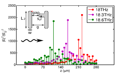
COMSOL simulations of a -layer DCF-SL metamaterial, with the single-layer unit cell shown in the inset to Fig. 3, were performed. Note that this unit cell, while topologically equivalent to the one shown in Fig. 2, is optimized to decrease Ohmic losses. Antennas are assumed to be made of silver with the dielectric permittivity described by the Drude model Ordal et al. (1985). The structure is triply-periodic with the period m and embedded in a dielectric with . The SL’s frequency is adiabatically varied from layer to layer by increasing from m to m. Other unit cell parameters are given in the caption. Field intensity enhancements evaluated at the corner of the left vertical antenna are shown in Fig. 3 for different frequencies. As Fig. 3 shows, different frequencies are slowed down inside different layers as indicating the corresponding field enhancement. Thus, light is slowed down over the entire spectral band .
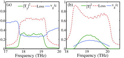
To underscore the advantages of the DCF-based approach to broadband SL, we compare a multilayer DCF-SL structure (unit cell is shown in Fig. 3) with its EIT-based counterpart (unit cell shown in Fig. 2, geometric parameters are given in the caption to Fig. 4). Both structures are based on silver antennas embedded in an dielectric. Figure 4 (a) and (b) shows the COMSOL simulations results for DCF-SL and EIT-SL structures, respectively. The group velocity is calculated as , where is the total length of the structure and is the phase difference between incident and transmitted waves. In the case of EIT, the bandwidth can be potentially increased by increasing the coupling between dipole mode and quadrupole mode (). However, it comes at the expense of the increased group velocity dispersion and transmission non-uniformity.
Specifically, both and transmittance increase in the middle of the EIT band while remaining small near the EIT band edge. In contrast, the adiabatic DCF layers provide uniform group velocity as well as uniform cross-polarized transmittance inside the SL band. The bandwidth can be increased further simply by adding more adiabatically-varying layers. Note that the group velocity in the DCF-SL structure plotted in Fig. 4 is averaged over layers. Inside the specific resonant layer, the group velocity of the corresponding frequency component is , which is consistent with the intensity enhancement of three orders of magnitude. The spectrally-flat transmission and absorption of the DCF-based metamaterial is appealing to a variety of linear and nonlinear applications. Moreover, because every frequency component is dramatically slowed down in a well-defined layer, applications to spectrally-selective active light manipulation can be envisioned.
In conclusion, we have proposed a new mechanism of slowing down light over a spectrally broad band by means of low-symmetry metamaterials exhibiting double-continuum Fano (DCF) resonance. This approach is conceptually different from the more common EIT-SL. It is shown that DCF-based broadband slow light with uniform group velocity and transmittance can be achieved by adiabatically changing the DCF resonance frequencies along the light propagation direction. Spectrally-flat light absorbers and filters, as well as various nonlinear devices requiring extreme light concentration are enabled by DCF-based slow-light metamaterials.
This work was supported by the grants from the Air Force Research Laboratory and the Office of Naval Research.
References
- Hau et al. (1999) L. V. Hau, S. E. Harris, Z. Dutton, and C. H. Behroozi, Nature 397, 594 (1999).
- Krauss (2008) T. F. Krauss, Nature Photonics 2, 448 (2008).
- Zhu et al. (2007) Z. Zhu, D. J. Gauthier, and R. W. Boyd, Science 318, 1748 (2007).
- Harris (1997) S. E. Harris, Physics Today 7, 39 (1997).
- Budker et al. (1999) D. Budker, D. F. Kimball, S. M. Rochester, and V. V. Yashchuk, Phys. Rev. Lett. 83, 1767 (1999).
- Shvets and Wurtele (2002) G. Shvets and J. S. Wurtele, Phys. Rev. Lett. 89, 115003 (2002).
- Avitzour and Shvets (2008) Y. Avitzour and G. Shvets, Phys. Rev. Lett. 100, 065006 (2008).
- Zhang et al. (2008) S. Zhang, D. A. Genov, Y. Wang, M. Liu, and X. Zhang, Phys. Rev. Lett. 101, 047401 (2008).
- Papasimakis et al. (2008) N. Papasimakis, V. A. Fedotov, N. I. Zheludev, and S. L. Prosvirnin, Phys. Rev. Lett 101, 253903 (2008).
- Liu et al. (2009) N. Liu, L. Langguth, T. Weiss, J. Kastel, M. Fleischhauer, T. Pfau, and H. Giessen, Nature Materials 8, 758 (2009).
- Fano (1961) U. Fano, Phys. Rev. 124, 1866 1878 (1961).
- Miroshnichenko et al. (2010) A. E. Miroshnichenko, S. Flach, and Y. S. Kivshar, Rev. Mod. Phys. 82, 2257 (2010).
- Luk yanchuk et al. (2010) B. Luk yanchuk, N. I. Zheludev, S. A. Maier, N. J. Halas, P. Nordlander, H. Giessen, and C. T. Chong, Nature Materials 9, 707 (2010).
- Tsakmakidis et al. (2007) K. L. Tsakmakidis, A. D. Boardman, and O. Hess, Nature 450, 397 (2007).
- Gan et al. (2008) Q. Gan, Z. Fu, Y. J. Ding, and F. J. Bartoli, Phys. Rev. Lett. 100, 256803 (2008).
- Ordal et al. (1985) M. A. Ordal, R. J. Bell, R. W. Alexander, L. L. Long, and M. R. Querry, Applied Optics 24, 4493 (1985).