Addendum to “Single photon logic gates using minimum resources”
Abstract
The authors call attention to a previous work [Qing Lin and Bing He, Phys. Rev. A 80, 042310 (2009)] on the realization of multi-qubit logic gates with controlled-path and merging gate. We supplement the work by showing how to efficiently build realistic quantum circuits in this approach and giving the guiding rules for the task.
pacs:
03.67.Lx, 42.50.Ex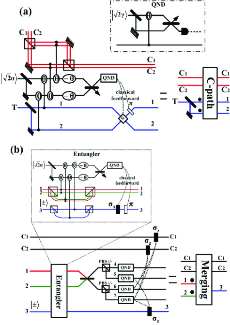
A core element for quantum computer is quantum logic gate. The realization of photonic logic gates is one of the main directions in the research of optical quantum computing. Compared with the linear optical approach klm ; l-review , deterministic photonic gates enjoy the advantages of efficiency and simplicity. The realizations of such gates are proposed mostly with nonlinear optical process such as cross phase modulation (XPM) in Kerr media p-p . In this approach, qubits in the basis can be simply encoded with photon number, polarization or spatial modes of single photons, and a gate operation dispenses with complicated ancilla photonic states. For example, an XPM between two photons directly implements a controlled phase gate with the transformation (with , and being unchanged). However, due to technical challenges, a value of in the order of radian could be difficult to come by. One feasible substitute is the weak nonlinearity approach w-n1 ; w-n2 . It is to couple coherent states of a large amplitude to single photons for the transformation , where could be rather small. Then the processed coherent states are measured for projecting out the proper output states of the single photons, which should be obtained by gate operation. Recently we developed the approach further by proposing an architecture using two element gates—controlled-path (C-path) and merging gate—for single-photon logic gates Lin2 . Multiple qubit control gates such as the Fredkin and the Toffoli gate, which are under extensive studies recently a1 ; a2 ; a3 ; a4 ; a5 ; a6 ; a7 ; a8 , can be efficiently realized by the combinations of the two element gates. This Brief Report supplements the previous study from the view of constructing the realistic circuits for implementing quantum algorithms.
A quantum circuit consists of various ingredients, e.g., single qubit gates, two-qubit gates, multi-control gates, etc. Individually all control gates involving more than two qubits can be realized with pair(s) of C-path and merging gate, together with the necessary single qubit gates Lin2 . A prominent feature in a realistic quantum circuit is that more than one control operation could be acted on a particular target qubit, so the photon to encode the target qubit should be separated by C-path gates and merged by merging gates again and again if we straightforwardly apply the elementary gates to implement a circuit operation. Actually such repetition can be saved if one modifies C-path and merging gate a little bit. Then a target photon could be merged only after all control operations have been performed on it, thus greatly simplifying circuit structure by reducing the number of the merging gates. Such simplification is particularly relevant to circuit operations involving large number of qubits, e.g., the implementation of quantum algorithms. To fulfill the simplification, a new element—the eraser for eliminating the unwanted photon correlations between the successive C-path gate operations, should be introduced, as we will explain below.
The control photon in an original C-path or merging gate carries only one spatial mode Lin1 ; Lin2 . Here we make a modification in the design so that a photon with more than one spatial mode could control the path of another photon (a similar modification in a special case is given in Lin3 ). In Fig. 1(a), we suppose that the input state (resulting from the action of the previous logic gates) for the gate is
| (1) | |||||
where denote the different spatial modes of the control photon, denote the polarization modes, and the components of the target photon is , where . The special forms of such inputs with or can be processed by the original C-path gate in Lin2 ; Lin3 ; Lin1 . We first use a 50:50 beam splitter (BS) to divide the target photon into two different spatial modes:
| (2) |
where the index and denote two different paths. And then, following the coupling patterns of XPM in Fig. 1(a), i.e., the first (second) coherent state is coupled to mode 1 (2) of the target and () mode on both and for the control photon, we will obtain the following total state (the global coefficient is neglected):
| (3) | |||||
After a phase shifter and a 50:50 beam splitter (BS) implementing the transformation are performed on the two ancilla beams, the eight terms in the above equation can be projected into two groups of output state by a photon number projection on one of the output beams, which could be in the state or . By the path switch and a phase shift on the target photon, which is conditioned on the measurement results , the two-photon state from both of the groups can be transformed to
| (4) |
thus realizing a deterministic control of the target photon’s paths by the polarizations ( and ) of the control photon carrying two spatial modes. The projection is implemented by a QND module, in which a beam in the state (where is large) is coupled to the above-mentioned output ancilla beam through an XPM implementing the transformation . Even if , the output coherent states can be still well separated with respect to their Poisson distributions of photon numbers, given a sufficiently large . Thus, a number non-resolving detector even without high detecting efficiency or a quadrature measurement can indirectly realize the deterministic photon number resolving detection corresponding to (see Lin3 for the details). The progress on the physical realization of such XPM based QND refers to, e.g., qnd1 ; qnd2 ; qnd3 ; qnd4 . The number of the controlling spatial modes for the C-path gate can be straightforwardly generalized to larger than two.
Similarly, we can modify a merging gate, which performs the inverse operation of the above C-path gate, see Fig. 1(b). By such merging gate with multi-spatial control modes, the output state in Eq. (4) can be transformed to
| (5) |
i.e., the merging of the target photon modes on path 1 and 2 to path 3.
Now we will put the element gates together to build a quantum circuit. Without loss of generality, we illustrate the architecture by a three-qubit circuit shown in dash-dotted line of Fig. 2. The input state for the circuit is (the global coefficient is neglected)
| (6) |
which could be either entangled or not entangled. Three CU operations and one Toffoli operation will be performed on the state. In the space where the qubits are encoded with the polarization modes of single photons, the CU operations are represented by the operators , where and . The Toffoli gate performs the operation .
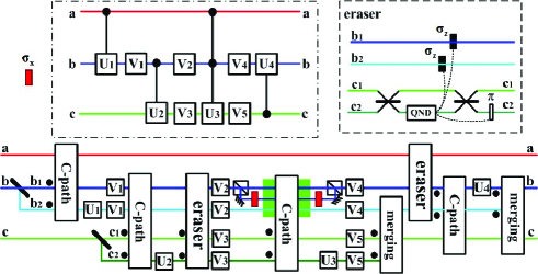
The first CU gate can be straightforwardly realized with a C-path gate plus single qubit operation . Before the implementation of the second CU operation involving photon and , we do not merge the spatial modes of photon and, instead, we directly use them to control the operation on the third photon in the next gate operation. The second CU operation can be implemented by a generalized C-path gate in Fig. 1(a), associated with the single-photon operation performed on the spatial mode .
The triple photon state after being processed by the first two CU gates is in the form
| (7) | |||||
where the specific forms of are determined by the operations , and the coefficients of the input state. The polarization modes of photon are entangled with the spatial modes of photon in the above expression ( of photon is always in the same terms with the spatial mode of photon , etc.). However, a proper state to be processed by the next C-path gate should be in the form of Eq. (2), where each polarization mode (irrespective of its spatial mode) for the control photon is in tensor product with the superposition of both spatial mode terms of the target photon. It is therefore necessary to eliminate such unwanted correlation between the polarizations of photon and spatial modes of photon .
We introduce a circuit ingredient illustrated in the dashed line of Fig. 2 for the purpose. The QND module here is the same as the previously described. After the interference of the spatial modes and by a 50:50 beam splitter (BS), a QND module projects the state to
| (8) |
Then one more BS, as well as the conditional operation on both spatial modes of photon and a conditional phase shift on the mode , depending on the classically feedforwarded detection results of the QND, will be applied. The whole operation will result in the state
| (9) |
which is similar to the form of the input in Eq. (2). We call this circuit ingredient an eraser.
Now the correlation between the polarization and spatial modes of photon and still exists, i.e., the mode of photon is always in the same terms with mode of photon , etc., see Eq. (9). This happens to be an advantage for implementing the following Toffoli gate. Then a C-path gate only by photon ’s polarizations on its all spatial paths will control the path of photon , thus realizing a Toffoli gate with a simplified structure from that in Lin2 .
It is not necessary to erase the correlation between the photons immediately after implementing the Toffoli gate, but the spatial modes of the third photon should be merged by a merging gate. There will be no control operation to be performed on this photon (photon ). The merging of its spatial modes will simplify the further control operation by itself. Before the final CU operation, one more eraser should be applied to eliminate the unwanted correlation between photon and .
The imperfections of the circuit operation could arise from losses of the photonic states. The decoherence effects on photonic states due to the losses in XPM and transmission are studied with the corresponding master equations in deco1 ; deco2 ; deco3 . In the implementation of the above circuit, the losses will mainly come from the XPM between single photon and coherent state if there is close to ideal performance of the linear optical components. It is shown in deco1 that, an XPM in lengthy optical fiber is impossible to avoid considerable decoherence, but the acceptable fidelities (with the ideal pure output states) could be achievable with the reasonable system parameters for the XPM in media under electromagnetically induced transparency (EIT) conditions. A feasible realization of the XPM between coherent and single photon state still awaits to be clarified further for building such photonic circuits.
The generalization to the circuits involving more qubits is straightforward. Here we give two examples for the implementation of quantum algorithms. The first is the Grover’s searching algorithm grover , which could be implemented with two-qubit gates Toffoli . The essential part of the algorithm is the following operation
| (10) |
where is the identity operator for qubits, and ( denotes Hadamard operations on qubits, respectively). The operator in the above equation is an -control Toffoli- gate, i.e., the logic of the first qubits conditions the operation on the -th qubit. Therefore, as a simple generalization from the two-qubit Toffoli gate in Fig. 2, it can be implemented with pairs of C-path and merging gates. Since the paths of the -th photon to encode the qubit is only controlled by the polarization modes of the -th photon, there are at most XPM operations including those in the QND modules for all C-path gates. Together with those of the merging gates, the total number of XPM operations should be , scaling linearly with the number of the involved qubits. Note that erasers are not necessary in this case. With the QND modules in the merging gates for preserving ancilla photon, in principle only one ancilla photon will be required for implementing the searching algorithm.
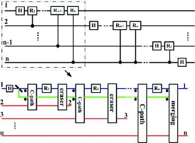
Another example is the Shor’s factoring algorithm shor . Quantum Fourier transformation (QFT) shown in the upper side of Fig. 3 is the crucial part for the algorithm. A QFT circuit consists of a series of qubit rotations controlled by other qubits. It can be realized with a regular combination of C-path and merging gates, see the lower side of Fig. 3. A general QFT circuit involving qubits consists of controlled rotations. It therefore demands C-path gates, erasers and merging gates for the realization in our architecture. Meanwhile, two points should be paid attention to in constructing such circuit:
(1) before implementing a two-qubit control gate, the correlation between the target photon and the previous control photon should be erased;
(2) if no further control operation is to be performed on a photon, its spatial modes should be merged with a merging gate.
Following these two rules, it is convenient to construct any quantum circuit with the modified C-path and merging gates. If one adopts the routine decomposition strategy into two-qubit and single-qubit gates for the realization of a quantum circuit (see, e.g., Nielsen ), the decomposition is generally irregular and the design could be rather complicated. Our architecture following the simple rules of combining C-path, merging gates, as well as erasers, considerably reduces such complexity.
Acknowledgements.
The authors thank Ru-Bing Yang for helpful suggestions. Q. L. was funded by National Natural Science Foundation of China (Grant No. 11005040) and the Natural Science Foundation of FuJian Province of China (Grant No. 2010J05008), and B. H. acknowledges the support by Alberta Innovates.References
- (1) E. Knill, R. Laflamme, and G. J.Milburn, Nature, 409 46, 2001.
- (2) P. Kok, W.J. Munro, K. Nemoto, T.C. Ralph, J. P. Dowling, G.J. Milburn, Rev. Mod. Phys. 79, 135 (2007).
- (3) I. L. Chuang and Y. Yamamoto, Phys. Rev. A 52, 3489 (1995).
- (4) K. Nemoto, W. J. Munro, Phys. Rev. Lett. 93, 250502 (2004).
- (5) W. J. Munro, K. Nemoto, T. P. Spiller, New J. Phys. 7, 137 (2005)
- (6) Q. Lin and B. He, Phys. Rev. A 80, 042310 (2009).
- (7) J. Fiurášek, Phys. Rev. A 73, 062313 (2006).
- (8) G. J. Milburn, Phys. Rev. Lett. 62, 2124 (1989).
- (9) Y. X. Gong, G. C. Guo, and T. C. Ralph, Phys. Rev. A 78, 012305 (2008).
- (10) J. Fiurášek, Phys. Rev. A 78, 032317 (2008).
- (11) T. C. Ralph, K. J. Resch, and A. Gilchrist, Phys. Rev. A 75, 022313 (2007).
- (12) B. P. Lanyon et al., Nature Physics 5, 134 (2009).
- (13) M. S. Tame et al., Phys. Rev. A 79, 020302(R) (2009).
- (14) R. Ionicioiu, T. P. Spiller, and W. J. Munro, Phys. Rev. A 80, 012312 (2009).
- (15) Q. Lin, B. He, J. A. Bergou, and Y. H. Ren, Phys. Rev. A 80, 042311 (2009).
- (16) Q. Lin and J. Li, Phys. Rev. A 79, 022301 (2009).
- (17) N. Imoto, H. A. Haus and Y. Yamamoto, Phys. Rev. A 32, 2287 (1985).
- (18) Yun-Feng Xiao et al., Optics Express,16, 21462(2008).
- (19) H. F. Hofmann and H. Nishitani, Phys. Rev. A 80, 013822 (2009).
- (20) N. Matsuda et al., Nature Photonics 3, (2009).
- (21) B. He, M. Nadeem, and J. A. Bergou, Phys. Rev. A, 79, 035802 (2009).
- (22) B. He, Y.-H. Ren, J. A. Bergou, Phys. Rev. A, 79, 052323 (2009).
- (23) B. He, Y.-H. Ren, and J. A. Bergou, J. Phys. B: At. Mol. Opt. Phys. 43, 025502 (2010).
- (24) L. K. Grover, Phys. Rev. Lett. 79, 325 (1997).
- (25) A. Barenco et al., Phys. Rev. A 52, 3457 (1995).
- (26) P. W. Shor, In Processings, 35th Annual Symposium on Foundations of Computer Science, IEEE Press, Los Alamitos, CA, 1994.
- (27) M. A. Nielsen and I. L. Chuang, Quantum Computation and Quantum Information (Cambridge University Press, Cambridge, UK, 2000).