The CALICE Software Framework and Operational Experience
Abstract
The CALICE collaboration is developing calorimeters for a future linear collider, and has collected a large amount of physics data during test beam efforts. For the analysis of these data, standard software available for linear collider detector studies is applied. This software provides reconstruction of raw data, simulation, digitization and data management, which is based on grid tools. The data format for analysis is compatible with the general linear collider software. Moreover, existing frameworks such as Marlin are employed for the CALICE software needs. The structure and features of the software framework are reported here as well as results from the application of this software to test beam data.
I Introduction
The CALICE collaboration [1] is formed of more than 300 physicists and engineers from Europe, America, Asia and Africa. Its purpose is to carry on a research and development program of hadronic and electromagnetic calorimeters for a future Linear Collider at the TeV scale.
Several test beam campaigns (see Tab. I) were successfully performed by the collaboration with different combinations of detectors: a hadronic calorimeter (HCAL) using steel or tungsten as absorber and scintillator tiles, read out by silicon photomultipliers (SiPMs), as active material [2], a Si-W ECAL [3], a Tail Catcher and a digital HCAL based on gas proportional chambers (RPCs) [4].
The detectors were accompanied by DAQ systems, triggers and drift chambers, which provide tracking information. The test beam campaigns resulted in several tens of terabytes of data saved on tape. For lasting physics results, it has to be insured that the data are treated consistently, despite the different types of detectors, and their different states of development.
In the following, the efforts done by the CALICE collaboration in developing the software needed to extract relevant physics results are presented.
| Location | Year | Detectors |
|---|---|---|
| DESY | 2006 | Scintillator/steel HCAL |
| CERN | 2007 | Si-W ECAL, |
| scintillator/steel HCAL, | ||
| Tail Catcher | ||
| FNAL | 2007/2008 | Si-W ECAL, |
| scintillator/steel HCAL, | ||
| Tail Catcher | ||
| FNAL | 2009 | Scintillator ECAL, |
| scintillator/steel HCAL, | ||
| Tail Catcher | ||
| CERN | 2010 | Scintillator/tungsten HCAL |
| FNAL | 2010 | Digital HCAL |
II The CALICE Data Flow
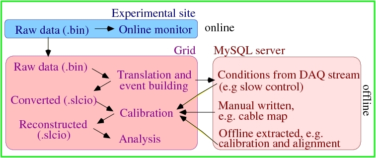
At the experimental site, the data are recorded in binary format and then transferred directly to the grid storage elements at DESY Hamburg, which provides a tape back-up, and replicated, for safety reasons, at the Computing Centre of IN2P3 at Lyon. The event building is also done on the grid and generates files in the LCIO format (see section III). Since the year 2005, a total of about 50 TByte of raw and processed data and simulation files have been managed using grid, i.e lcg tools [5].
In order to be analysed, the data need to be calibrated first. The calibration depends on the detector type and usually implies the usage of so-called calibration constants, which are extracted offline.
For a common storage of all calibration constants, the mappings of the different channels and alignment information, a MySQL data base, hosted at DESY, is employed by CALICE. Some of the information is written into the data base during conversion and some, like calibration constants, at a later stage by experts. Once the best available information is written to the data base, the corresponding folders are tagged. This ensures that the results can be reproduced and cross-checked later without problems.
The access to the data base is done based on IP-ranges. As soon as a new group joins the collaboration, their IP-ranges are added to the list. Even if the access to the data base may be sometimes slow from remote locations (like Japan), there is always the possibility of dumping the data base information on files which can be stored locally.
Actually, there are two instances of the data base: one for reading, available for everybody, and one for writing and reading, for experts work. The experts need to provide a password in order to be able to modify the contents of the data base. For test purposes, user folders are created. Once the expert is satisfied with the results, the information is copied to the central folders.
A schematic representation of the CALICE data flow is shown in Fig. 1.
The mass reconstruction is done centrally, upon request. This is based on jobs submitted to the grid (involving centres from all over Europe), as well as local batch farms. Once the data is calibrated (i.e. reconstructed), it can be analysed.
III The Structure of the CALICE Software
The CALICE software is based on the ILC software [6]. It uses the C++ programming language, and the cmake [7] tool for creating platform independent Makefiles. The documentation is done mainly inside the code, using doxygen [8].
The development is done by people from the various groups. There is a designated responsible for each group, and they are coordinated by a central software person.
The software is maintained with an SVN server hosted by DESY [9], and is organised in packages:
-
•
calice_userlib Contains general purpose classes, used in the other packages
-
•
calice_reco The main package, contains the reconstruction code for the scintillator HCAL, Si-W ECAL and for the Tail Catcher
-
•
calice_lcioconv Does the conversion from binary to LCIO format
-
•
calice_sim Includes digitisation of simulated events
-
•
calice_run Contains bash scripts for automatic generation of steering files, used for reconstruction, noise extraction and for the digitisation
-
•
calice_torso Contains , as start-up for new users
In addition, an external package, called RootTreeWriter, is used to create ROOT trees for simple analyses.
The software releases are announced on the main web page [10] and on dedicated mailing lists. With every release, a tar-ball is created and installed on the grid, for subsequent usage.
The simulation is realised by Mokka [11], which provides the geometry interface to the GEANT4 [12] simulation toolkit and is also used for full detector simulation studies. In order to save time, the digitisation step, performed in the calice_sim package is separated from the time consuming simulation step. The simulation and digitisation of the data runs are done centrally, upon request.
III-A CALICE Event Displays
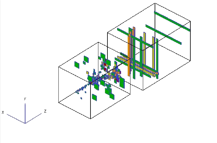
For displaying CALICE test beam events, currently two displays can be used: one based on CED, which is the standard ILC event display, used also for the full detector, and one based on ROOT geometry classes, named DRUID [13]. An example of such an event display is shown in Fig. 2.
III-B Testing
Before each release, it is tested if the software compiles, and if it produces the expected results. Nevertheless, since mistakes can always happen, a better solution is to do the testing in an automatised way, and to be able to easily compare results obtained with previous software tags. This is done for the CALICE software using ctest [14], which is a tool coming for free with cmake. This tool can be used for automatic updating from SVN, for configuring, building, testing, memory checking and for submitting results to a CDash dashboard system. CALICE uses the CDash server installed by the ILC software group at DESY Hamburg. Apart from automatisation, this has the advantage that the outcome of the tests is stored in a central place, and the view of the history in time is possible.
First basic ctest scripts are already being used for several CALICE packages (calice_userlib, calice_reco and calice_sim).
IV Application of the CALICE Software - PandoraPFA
In the beginning years of the collaboration, the software was written in view of the immediate needs of the specific group. As the groups evolved, more and more accent was put on modularity and flexibility, since new coming detectors need to be integrated easily. In addition, CALICE profits from the close collaboration with the ILC core software developers. The advantages of this integrated strategy are underlined by a recent analysis in which data recorded in test beam were subject to an analysis using tools developed for the full detector studies [15], namely the Pandora Particle Flow Algorithm (PFA) [16].
The aim of building a very high granular calorimeter is the capability to measure the details of hadron showers and ultimately recover neutral hadron energies in the vicinity of charged hadrons. This leads to an increased overall jet energy resolution (), since the energy of charged particles can be measured in the tracking detectors with much higher resolution than in the calorimeters. The resolution is degraded by the false assignment of hits to overlapping particle showers from charged and neutral particles. This depends on the deposited energy in the calorimeter as well as on the distance of the showers.
To study these effects test beam data samples with charged pions with energies from 10 to 50 GeV have been used, which were taken during the CERN test beam runs in 2007. The aim is to study the dependence of the energy recovery capability of the PFA in events containing two pions of the pion energies and their distance. The events containing two pions have been constructed by overlaying two single pion events, of which the energies have been measured with the standard procedure in the calorimeter, and varying their energy and distance of the shower axes. Additionally it has been assumed that one of the pions is neutral and it has been studied how well the energy of this pion is recovered by the PFA, after having mapped the event topology to a Linear Collider detector geometry.
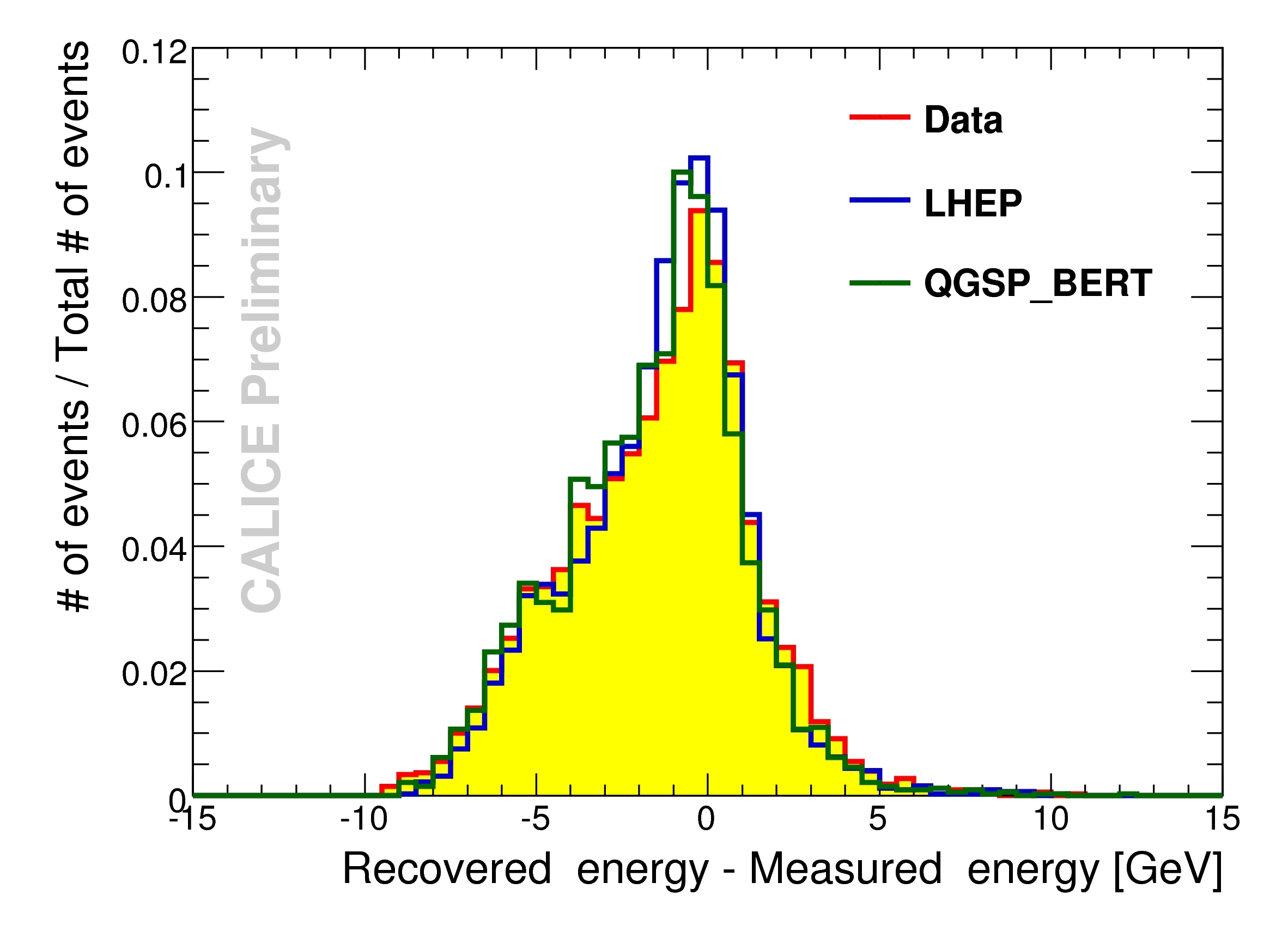
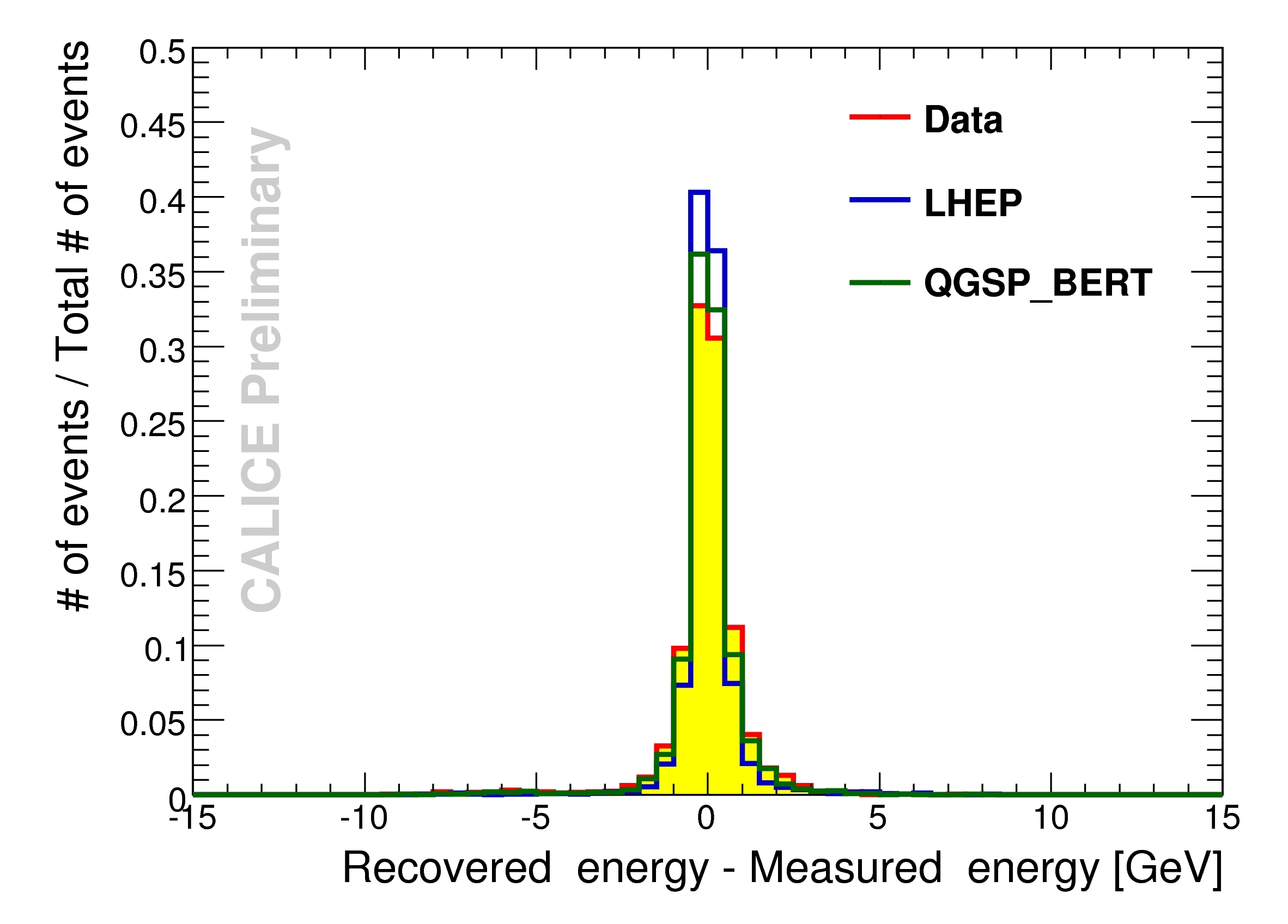
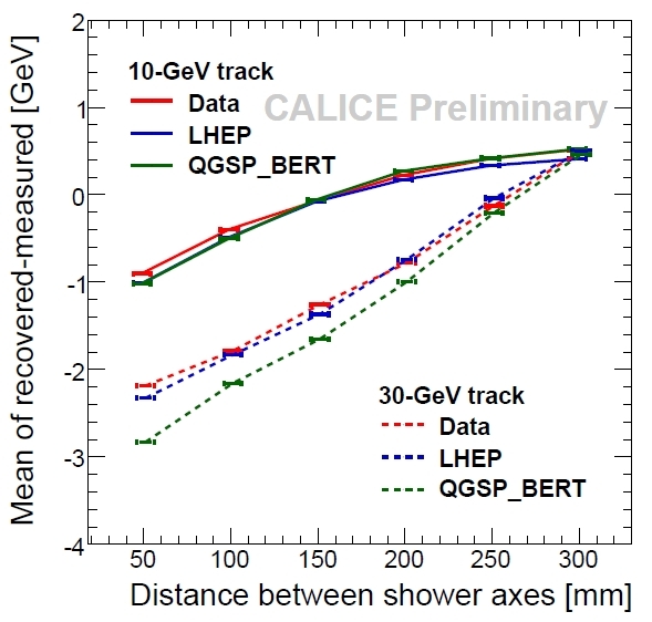
Fig. 3 shows the difference between the recovered energy and the previously measured energy of a 10 GeV neutral pion in the vicinity of a 10 GeV charged pion with a distance of 5 cm. The distribution is very broad and degrades even further for higher charged pion energies. As a comparison Fig. 4 shows the difference between the recovered energy and the previously measured energy for pions of the same energy, but with a distance of 30 cm. The width of the distribution is considerably smaller, which shows that the expected behaviour is reproduced by the algorithm. In both plots not only the test beam data distribution is shown, but also the MC predictions of the LHEP model and the QGSB_BERT model. Apparently, the simulation reproduces the results of the test beam data very well. A summary plot showing the mean of the difference between the recovered energy and the measured energy as a function of the distance of the shower axes for two different charged pion energies is given in Fig. 5. As discussed, the confusion depends on the radial distance between the showers, i.e. the showers overlap more at smaller distances. Again, good agreement between data and MC predictions is visible, which shows that the PandoraPFA is a reliable reconstruction program for a full size detecctor.
V Conclusions and Outlook
The CALICE collaboration has operated several test beam campaigns over the last years and the analysis of the data requires powerful software tools. This incorporates the data reconstruction and analysis as well as the data management. The CALICE software makes use of the developments done for the ILC analysis software and is fully integrated into this framework. In particular Marlin processors are used for the analysis and Mokka as the simulation framework. The worldwide computing grid is heavily used both for data storage and data processing. The CALICE software has been shown to scale for large data sets during years of test beam data analysis. A study of the PandoraPFA algorithm has been presented as an example of the successful application of the CALICE software in data analysis and it shows that it provides a reliable reconstruction for a full size experiment.
The next step for the development of the CALICE software is the integration of the technological prototypes as well as the Digital HCAL (DHCAL) and the Semi-Digital HCAL (SDHCAL). Integration means for example the usage of the LCIO data format and the common CALICE data base. This is necessary, since the DHCAL started taking test beam data recently and the SDHCAL will start data taking in 2011. Furthermore, the second generation of the CALICE DAQ is currently under development and has to be fully integrated into the CALICE software.
Acknowledgment
The authors gratefully thank the whole CALICE collaboration for the successful development and operation of the software framework as well as for useful discussions and contributions to the results presented here.
The software development has profited a lot from the close collaboration with the ILC core software developpers, who offer the framework, and continuous support. In addition, the data management is strongly supported by the DESY grid groups.
References
- [1] https://twiki.cern.ch/twiki/bin/view/CALICE/WebHome
- [2] C. Adloff et al., JINST 5, P05004 (2010) [arXiv:1003.2662 [physics.ins-det]].
- [3] J. Repond et al. [CALICE Collaboration], JINST 3, P08001 (2008) [arXiv:0805.4833 [physics.ins-det]].
- [4] B. Bilki et al., JINST 4, P10008 (2009) [arXiv:0908.4236 [physics.ins-det]].
- [5] http://lcg.web.cern.ch/lcg/
- [6] http://ilcsoft.desy.de/portal
- [7] http://www.cmake.org/
- [8] http://www.stack.nl/ dimitri/doxygen/
- [9] https://svnsrv.desy.de/websvn/wsvn/General.calice?
- [10] https://twiki.cern.ch/twiki/bin/view/CALICE/SoftwareMain
- [11] http://polzope.in2p3.fr:8081/MOKKA
- [12] http://geant4.cern.ch/
- [13] http://llr.in2p3.fr/ ruan/ILDDisplay/DruidNote.pdf
- [14] http://www.cmake.org/Wiki/CMake_Testing_With_CTest
- [15] O. Markin for the CALICE collaboration, PandoraPFA Tests using Overlaid Charged Pion Test Beam Data, to be published in CALOR2010 proceedings.
- [16] M. A. Thomson, Nucl. Instrum. Meth. A 611, 25 (2009) [arXiv:0907.3577 [physics.ins-det]].