Spin precession and modulation in ballistic cylindrical nanowires due to the Rashba effect
Abstract
The spin precession in a cylindrical semiconductor nanowire due to Rashba spin-orbit coupling has been investigated theoretically using an InAs nanowire containing a surface two-dimensional electron gas as a model. The eigenstates, energy-momentum dispersion, and the energy-magnetic field dispersion relation are determined by solving the Schrödinger equation in a cylindrical symmetry. The combination of states with the same total angular momentum but opposite spin orientation results in a periodic modulation of the axial spin component along the axis of the wire. Spin-precession about the wires axis is achieved by interference of two states with different total angular momentum. Because a superposition state with exact opposite spin precession exists at zero magnetic field, an oscillation of the spin orientation can be obtained. If an axially oriented magnetic field is applied, the spin gains an additional precessing component.
I Introduction
Semiconductor nanowires are almost ideal objects for studying quantum effects and electron interference phenomena. The use of the bottom-up approach for nanowire growth simplifies the preparation substantially and allows us to create novel confinement schemes, such as axial or radial heterostructures.Thelander et al. (2006); Lu and Lieber (2006) The large surface-to-volume ratio of nanowires means that surface properties are crucial for discussions of transport properties, so that low band-gap semiconductors, e.g. InAs, InN, or InSb, are particularly interesting. In these systems, the Fermi level at the surface is pinned inside the conduction band,Lüth (2010) and an accumulation layer is formed. This guarantees that the conductance is sufficiently large even at low nanowire radius. The presence of the surface accumulation layer means that a tubular conducting channel is formed, and this shape of the conductor has important implications for the magnetoconductance of the nanowires. An example is the theoretical prediction and experimental confirmation of flux-periodic oscillations in nanowires with a magnetic field applied along the wire axis. Tserkovnyak and Halperin (2006); Richter et al. (2008) The electronic states of a cylindrical two-dimensional electron gas in a transverse magnetic field were calculated by Ferrari et al.,Ferrari and Cuoghi (2008); Ferrari et al. (2008) while Magarill et al. Magarill et al. (1996, 1998) discussed the kinetics of electrons in a tubular conductor.
Many concepts have been developed for planar semiconductor layer systems that make use of the spin degree of freedom for device structures. The best-known example is the spin field-effect transistor,Datta and Das (1990); Egues et al. (2003); Schliemann et al. (2003) which uses the gate-controlled spin-precession induced by the Rashba effect. Nitta et al. (1997); Engels et al. (1997); Th. Schäpers et al. (1998) The Rashba spin-orbit coupling originates from a macroscopic electric field in an asymmetric quantum well.Bychkov and Rashba (1984) Meanwhile, research activities have been extended to planar quasi one-dimensional structures, which promise a superior spin control.Nitta et al. (1999); Kiselev and Kim (2001); Zülicke and Governale (2002) The energy spectrum and spin precession in these structures are governed by the interplay between confinement and energy splitting due to spin-orbit coupling. Guzenko et al. (2006, 2007) Only a few theoretical investigations have dealt with the effect of spin-orbit coupling in cylindrical conductors on the electronic states and on the quantum transport.Magarill et al. (1998); Tserkovnyak and Halperin (2006); Jin et al. (2010); Entin-Wohlman et al. (2010) The spin-dynamics in curved two-dimensional electron gases was discussed by Trushin and Schliemann Trushin and Schliemann (2008) while the weak antilocalization effect in cylindrical wires was studied by Wenk and Kettemann.Wenk and Kettemann (2010) The presence of spin-orbit coupling was confirmed for InN Petersen et al. (2009) and InAs semiconductor nanowires by measuring the weak antilocalization effect. Hansen et al. (2005); Dhara et al. (2009); Roulleau et al. (2010); Estévez Hernández et al. (2010)
The various possibilities of spin control in two-dimensional electron gases and planar wire structures opened up by the Rashba effect have inspired us to analyze theoretically the spin dynamics in tubular conductors. We have used a cylindrical InAs nanowire with a surface two-dimensional electron gas as a model system, but our findings also apply to other systems, e.g. InN or InSb nanowires. In Sect. II we analyze the electronic states, focusing on spin properties, and we discuss the conditions under which a spin precession can be observed in tubular nanowires at zero magnetic field (Sect. III) and in an axial magnetic field (Sect. IV). In Sect. V, we comment on the suitability of tubular conductors for spin electronic devices.
II Electrons in cylindrical wires
Electrons confined in a cylinder move along the axis with a linear momentum ( real) and around the axis with an angular momentum ( integer). As long as the translational and rotational symmetries of the cylinder are not perturbed these momenta are conserved quantities. The wave function of an electron
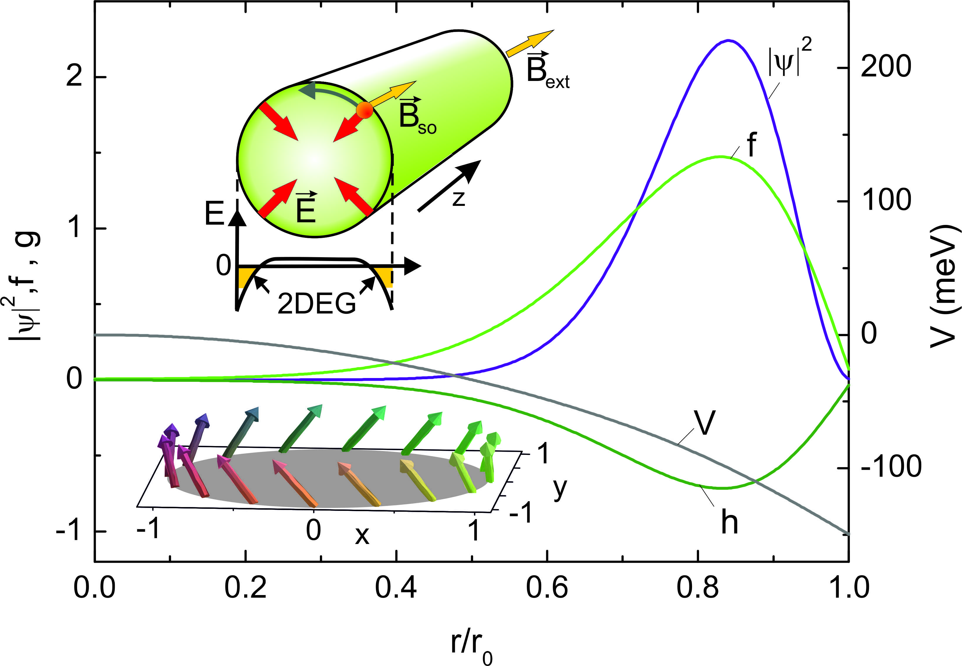
is a product of exponential functions in , the coordinate along the axis and the azimuthal angle around the axis respectively, and a radial distribution function . The distribution is determined by internal forces produced by the cylinder material. In our case, we took a planar 2-dimensional electron gas (2DEG) at the surface of InAs as a reference,Lamari (2003); Schierholz et al. (2004) i.e. assuming a surface state charge density of cm-2, a background -doping of cm-3 and an effective electron mass of . The calculations were done for a cylinder radius nm. A schematic illustration of the nanowire is depicted in Fig. 1 (upper inset). Electrons of atoms at the surface may find energetically more favorable states in the conduction band. Due to the Coulomb attraction between the electrons and the ions remaining at the surface the electrons get trapped in a layer close to the surface forming a 2DEG.Smit et al. (1989) The potential resulting from the charge density of occupied electron states , of ions at the surface and of dopants
| (1) |
is shown in Fig. 1. is the elementary charge, the spin index. is the bulk dielectric constant of InAs.Winkler (2003) It takes the polarization charges of the medium into account. The potential profile is determined by Poisson’s equation which is solved in cylindrical symmetry analytically
| (2) |
Equations (1) and (2) are solved self-consistently. Starting from the potential of a homogeneous distribution of electrons in the cylinder the distribution is recalculated using the Schrödinger equation given below [see Eq. (10)] and Eq. (1). The iteration procedure converges monotonically. We assumed an interface barrier of infinite height.
Due to the electric field across the surface of the cylinder the spin of the electron is coupled to its orbital motion
| (8) | |||||
The coupling-strength is determined by the band structure of the cylinder material ( nm2 for InAs).Winkler (2003) The second part of Eq. (8) expresses in terms of Pauli matrices for acting on a 2-component (spinor) wave function . The off-diagonal terms in raise (lower) the value of the orbital angular momentum of () by . The stationary states are eigenstates of the total angular momentum () with eigenvalues . The spinor is of the form:
| (9) |
where are real functions and solve the differential equations
| (10) |
Here, contains the contributions of the centrifugal force and the diagonal spin-orbit term, is the energy without the axial kinetic energy. At the wire boundary we assumed a barrier of infinite height.foo The influence of an external magnetic field is not included yet.
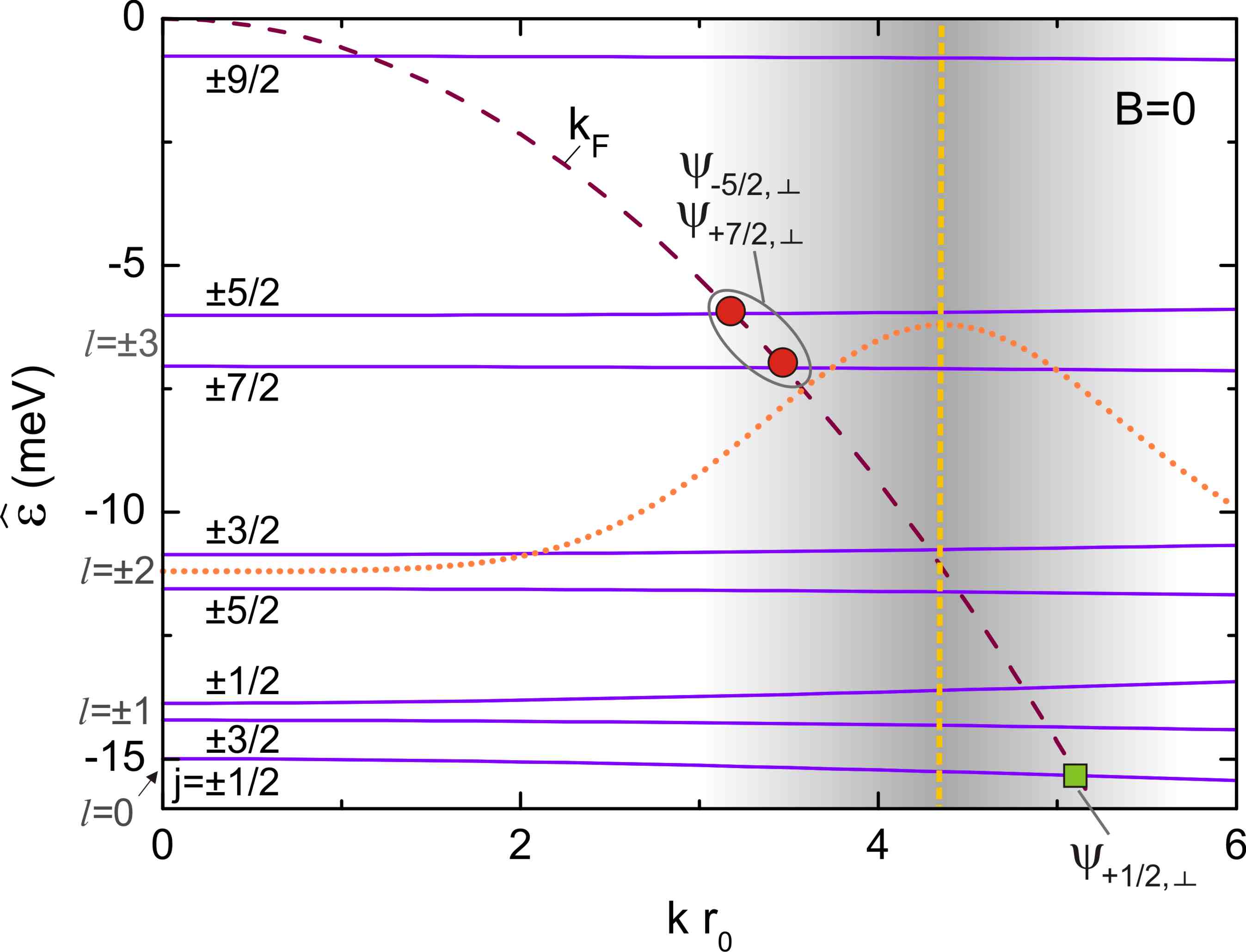
In Fig. 2 the energy is plotted for several -bands at . The parabola indicates the axial kinetic energy left out. It crosses the bands at the Fermi-momentum , i.e. states with energy below the parabola are occupied. At the coupling between and vanishes [cf. Eq. (8) ]. Classification with respect to is possible. The splitting between the second and third band () is caused by the diagonal part of and increases proportional to for the higher states. Due to the mirror symmetry states with angular momentum and spin reversed have the same energy. Therefore, all bands are twofold degenerate.
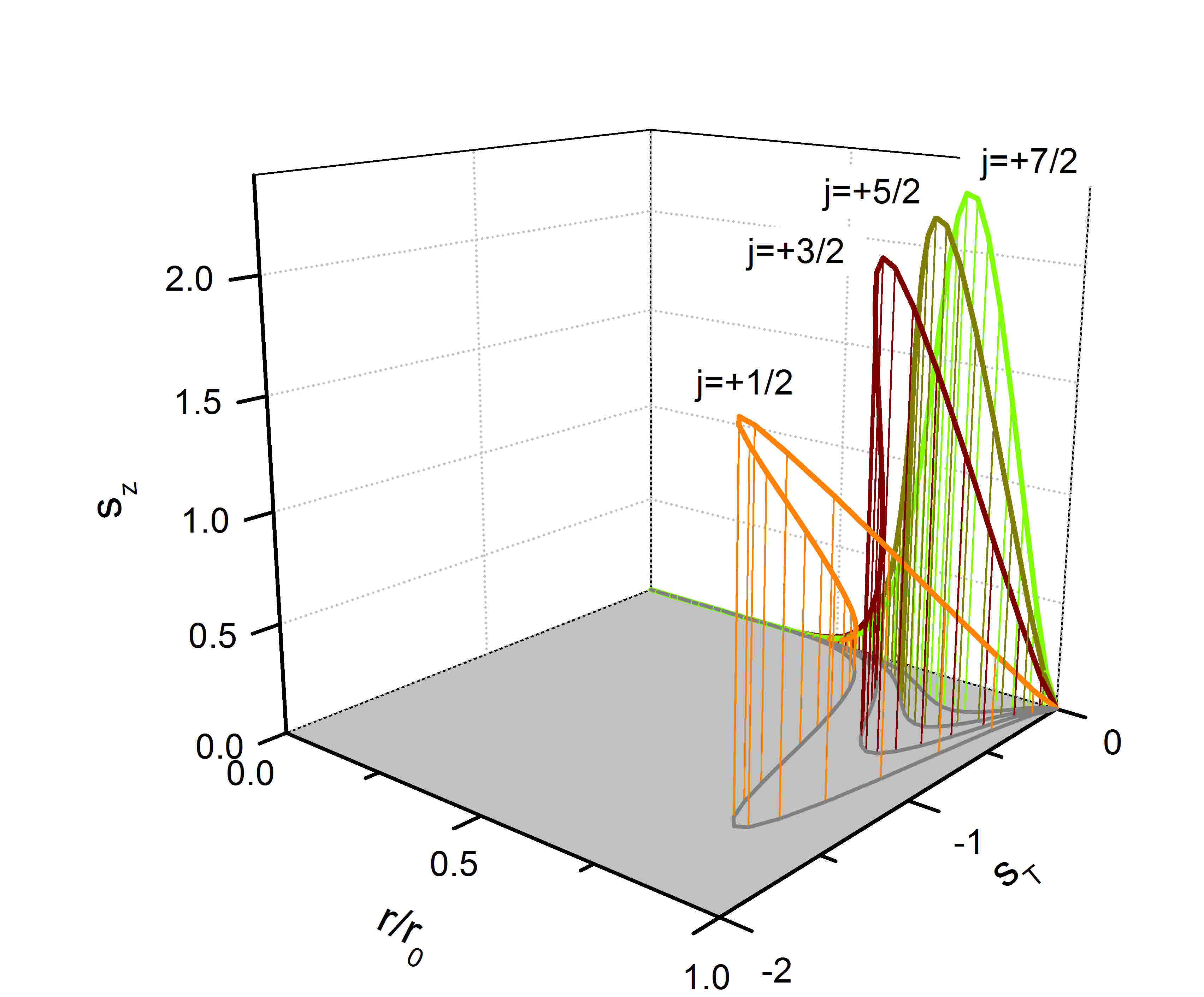
The solution of Eq. (10) for at is shown in Fig. 1. The spin-orbit coupling increases linearly with , i.e. at with there is the strongest spin-orbit coupling. The spin density attains a sizable tangential component
The component along the wire axis is
| (11) |
The radial component is zero. The spin orientation around the cylinder for is illustrated in Fig. 1 (lower inset). According to Eq. (11) the spin turns to the axial direction. This is shown for different values of in the plot of the spin densities and in Fig. 3. As can be seen here, the spin is oriented exclusively tangentially and along the axial direction. When averaged over the cylinder plane for each state the spin components and are zero, while a finite contribution remains along the -direction.
III Superposition States and Spin Precession
For each and there are two solutions of Eq. (10) . The (+)-state originates from , the ()-state from , the solutions at , with . They are orthogonal to each other and have opposite spin direction (). They have different energies and therefore different . Their superposition yields
The contributions of the basis states () almost cancel each other and are neglected further on. The interference between the states is constructive due to orthogonality and leads to
| (12) |
an oscillation of the average spin along the cylinder axis with a wavelength . The spin components , in the cylinder plane are both zero.
Superpositions of eigenstates with different ’s form states with a non-zero average spin component in the cylinder plane, e.g. . As one can easily retrace, these states originate from states with the same angular momentum . The interference term gives the only -independent contribution to the densities of . With
| (15) | |||||
| (18) |
the averages are
| (20) |
The contribution is small and does not depend on . In particular, for the superposition of the lowest two states is zero.
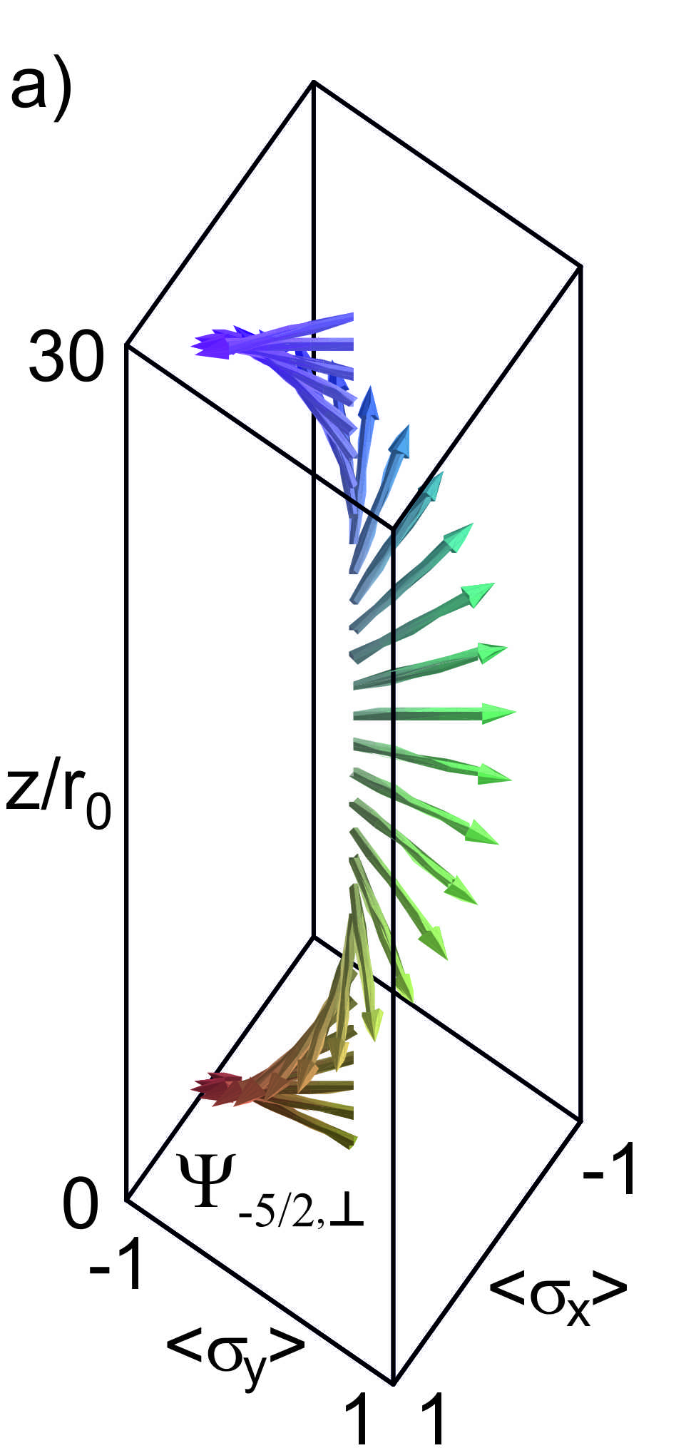
For , the superposition of and , the spin precesses counterclockwise in the cylinder plane along the cylinder axis, as illustrated in Fig. 4(a).
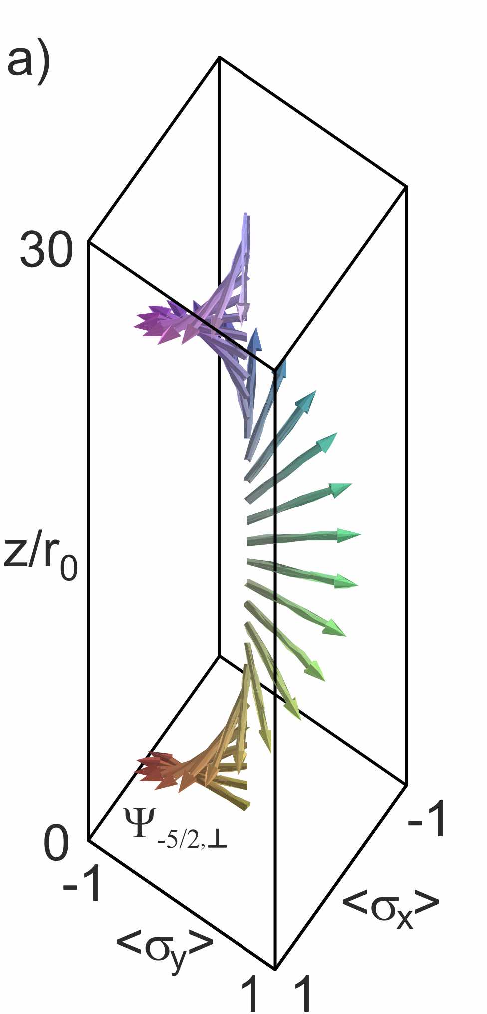

Here, we assumed an initial spin orientation along the direction, which in practice can be realized by spin injection from a spin-polarized electrode. For constituted of the opposite states and the spin precession is clockwise. Both precessions have the same period of . Their energy is degenerate. Due to their exactly inverse precession sense the combination of these states results in an oscillatory behavior of the net spin orientation, as depicted in Fig. 4(b). For an initial spin orientation along the direction the spin oscillates in the -plane. Superposition of the respective opposite states restores the left-right symmetry and eliminates spin precession. The oscillation period of depends on . For smaller , e.g. the corresponding difference in and becomes smaller so that the period is enlarged, as one can infer from Fig. 4(c) as compared to Fig. 4(b). The superposition state constituted of the two lowest lying energy states (cf. Fig. 2, square) shows no precession at all, because here and are identical. Figure 4(d) shows the spin variation for a Gaussian wave packet of width centered between the ’s of the states and . In position space this corresponds to a distribution of width . The oscillation deviates from a purely harmonic oscillation, as shown in Fig. 4(c), due to the contributions of the other states at the Fermi energy. This effect is also increasing with decreasing when the ’s get closer to each other.
The electron spin is usually injected from a spin-polarized electrode in all states at the Fermi energy having the correct spin direction. Thus, if only the direction of the spin is fixed by the electrode, all states are likely to transport electrons through the cylinder and a definite precession will not be observed. The total spin will only vary in the plane which is defined by the initial spin orientation and the -axis, similar to the situation illustrated in Fig. 4. In order to observe spin precession about the cylinder axis, a selection mechanism which breaks the left-right symmetry of the system must be adopted. As it will be discussed in the next section, this is achieved by applying a longitudinal magnetic field .
IV Spin Precession in a Magnetic Field
The vector potential of a longitudinal magnetic field introduces a paramagnetic (Zeeman-) and diamagnetic (Landau-) term into Eq. (10). is extended to
with the gyromagnetic-factor of the electron spin ( for InAsWinkler (2003)). The paramagnetic (second) term in raises for states with and lowers for states with . The energy difference increases for (cf. Fig. 5). For larger increase due to the diamagnetic (third) term. In the linear range the influence of the -dependence of the third term is negligible. The densities do not change significantly.
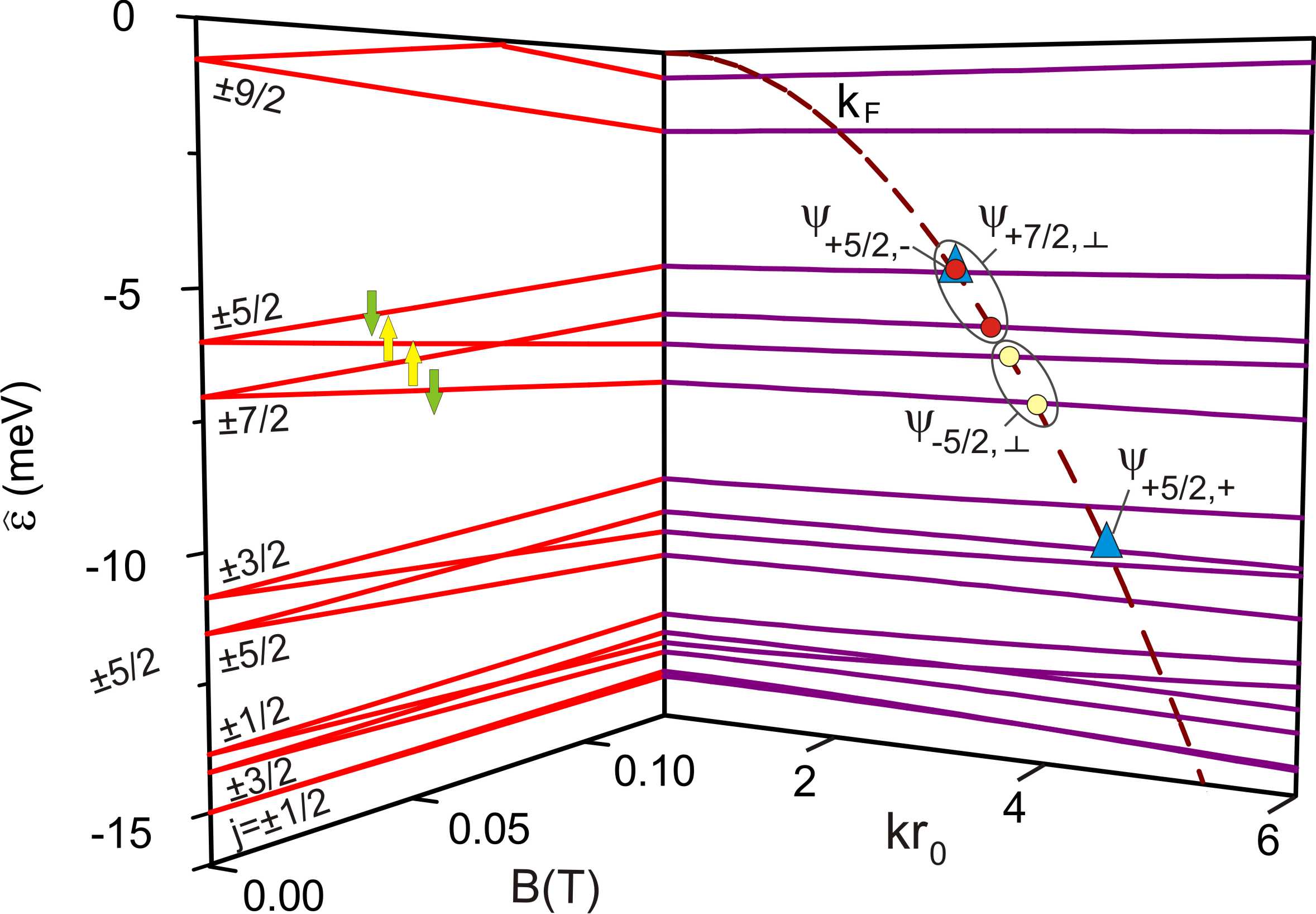
The main effect of is the energetic separation of the -states. It opens possibilities of observing spin dynamics in electronic transport. This will be demonstrated in the following at T. Figure 5 shows the -dependence at up to T and the -dependence at T of for states from to . Again, the parabola marks the Fermi edge. Superpositions with spin in the cylinder plane according to Eq. (20), are marked as pairs in Fig. 5. The lower pair corresponds to depicted in Fig. 4(a). As illustrated in Fig. 6(a), it shows the same counter-clockwise precession.
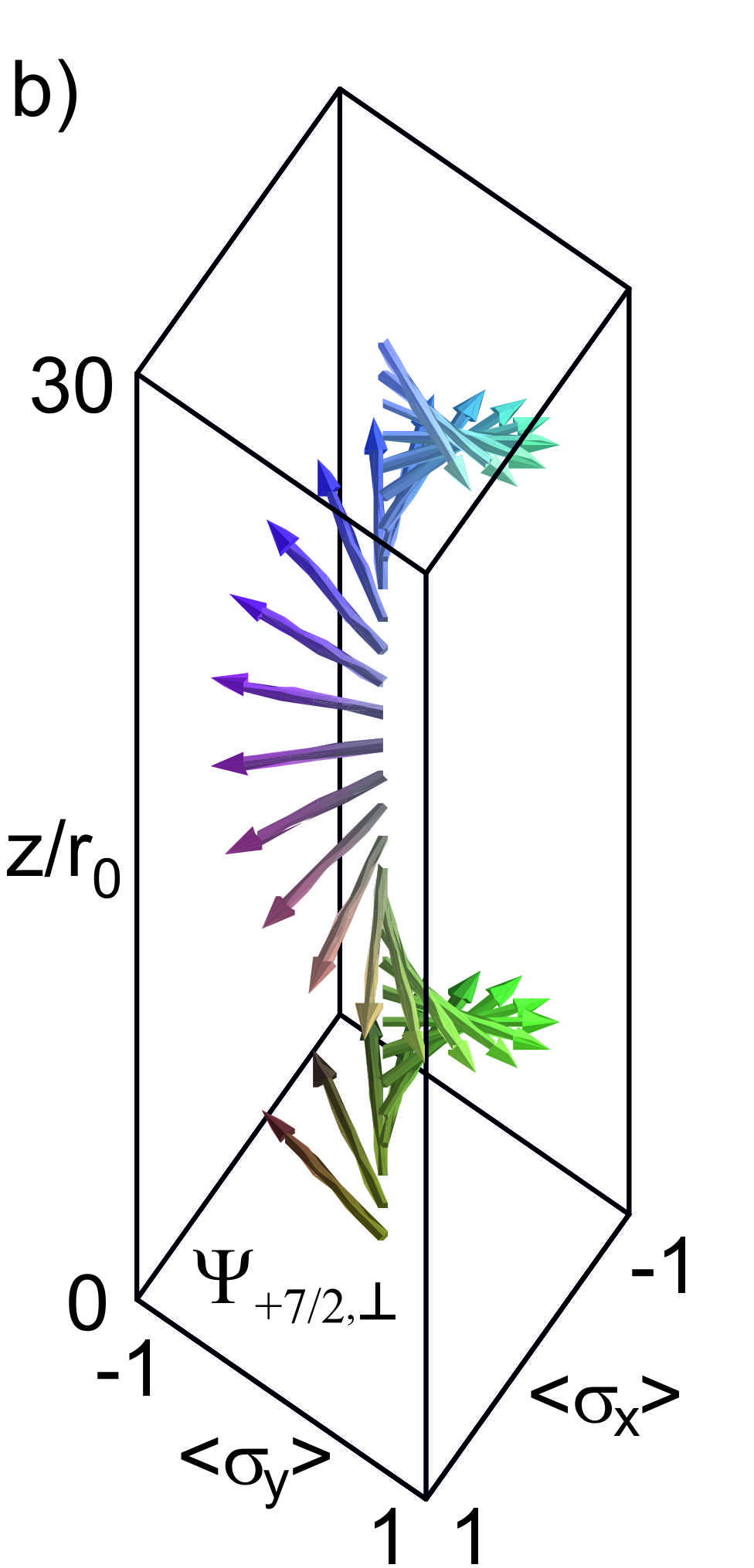
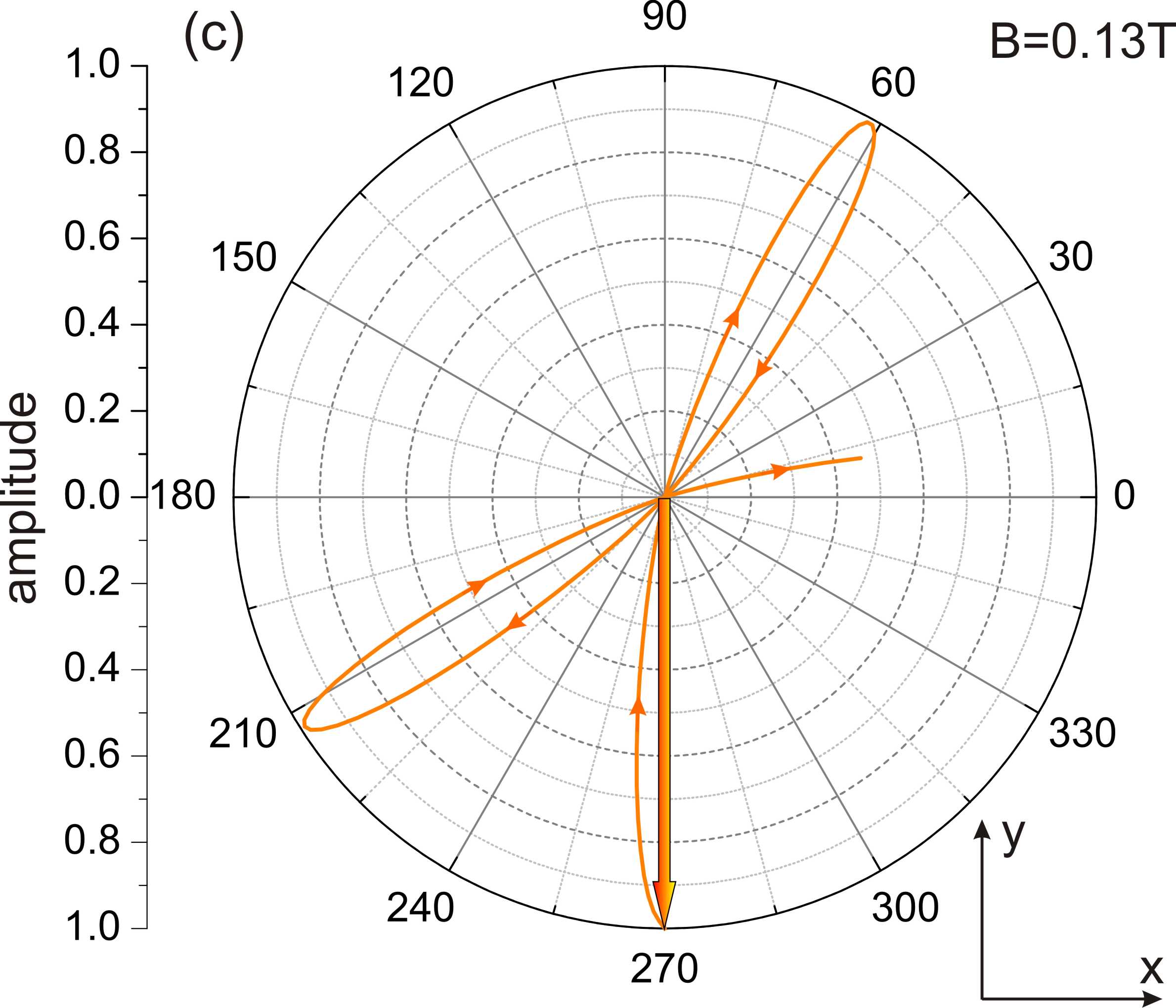
In contrast to the zero field case, now the superposition state has a larger -difference, i.e. a shorter precession length [cf. Fig. 6(b)]. Consequently, the precessions of and are not exactly opposite. In contrast to the case at , the spin still rotates following the state with the faster precession, when both states are superposed. This is illustrated in Fig. 6(c), where one finds that in addition to the oscillation of the spin amplitude its orientation is also changed during propagation. Thus, by applying a magnetic field a spin precession can be achieved.
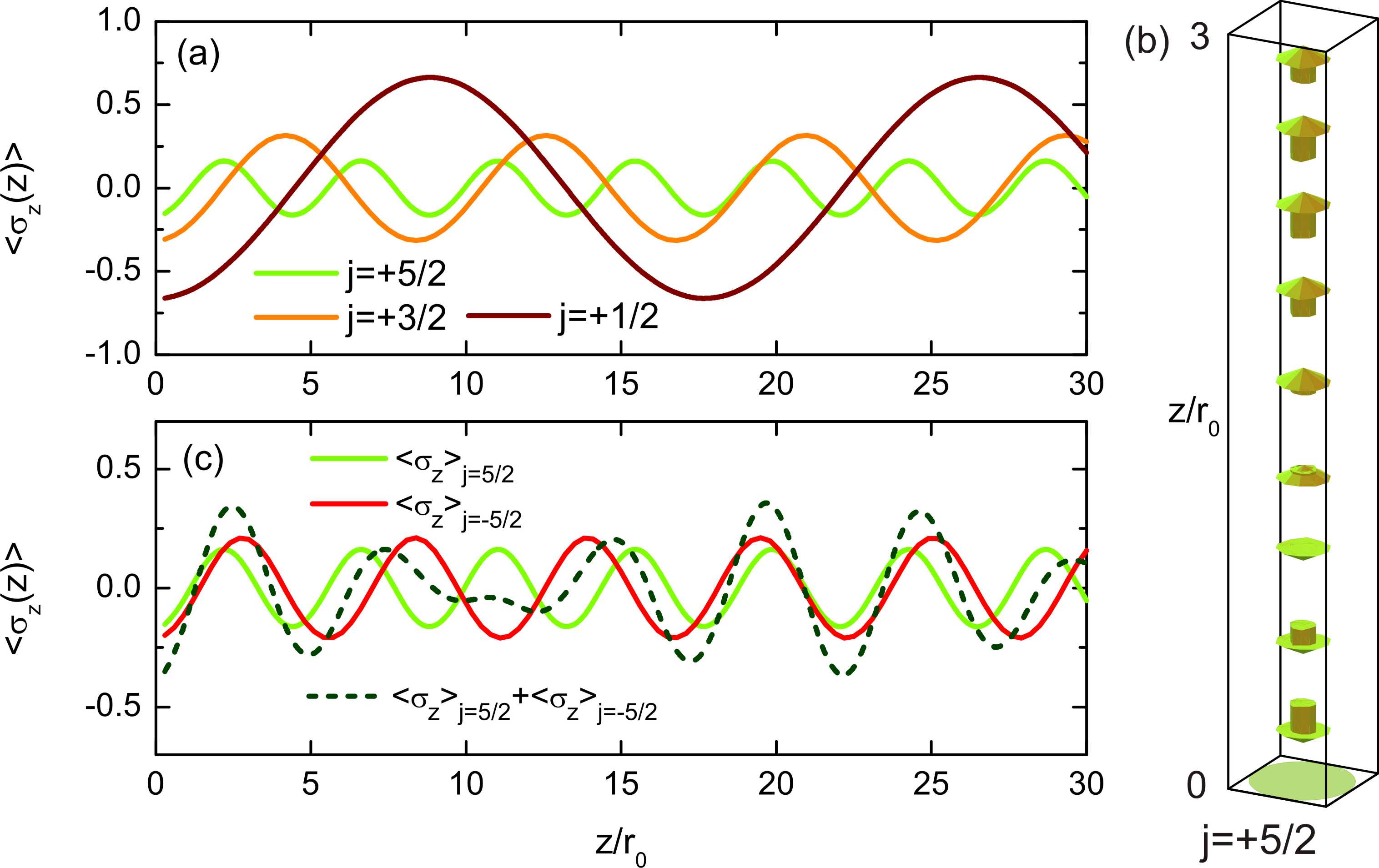
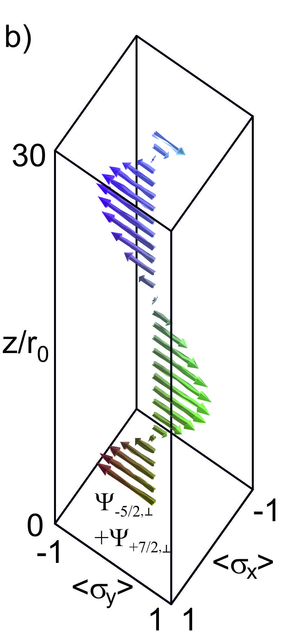
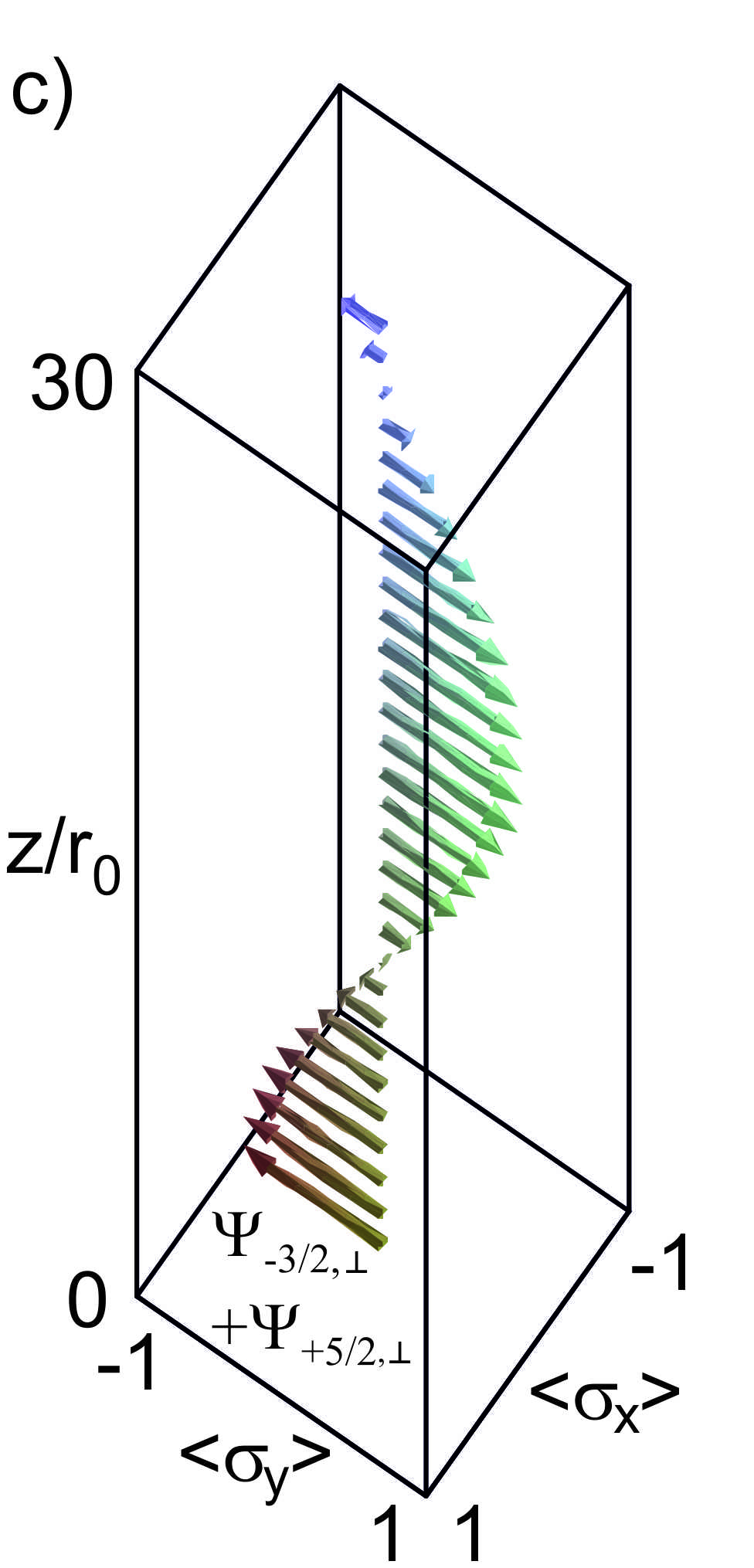
In the previous section, we already pointed out that the superposition state with equal total angular momentum but opposite spin orientation result in an oscillation of the average spin along the cylinder axis. In Fig. 7(a) and (b) these oscillations of are shown for different values of at T. One finds that for larger total angular momentum values the oscillation period is shorter owing to the larger difference of Fermi wave vectors. In Fig. 5 the states contributing to are marked by triangles. Compared to the previously discussed states, here the difference in the Fermi vectors is relatively large, leading to a faster oscillation compared to the spin precession period shown in Fig. 6(b).
Once again the application of an axial magnetic field breaks the symmetry of the states. As can be inferred from Fig. 7(c), a different oscillation period is found for the and states. Thus, when these states are combined a beating in the oscillation of the average spin appears.
V Conclusions
In the previous two sections we learned that an injected spin is strongly modulated while propagating through a cylindrical nanowire. For a spin injection along the wire axis, e.g. by a ferromagnetic electrode, the spin is carried by superposition states with equal total angular momenta. In analogy to the spin field-effect transistor based on a planar 2DEG,Datta and Das (1990) a transistor structure can be realized by placing a second magnetic electrode at the opposite terminal of the nanowire as a spin detector. Control of the spin orientation can achieved by manipulating the strength of the Rashba effect by means of a gate electrode. By applying a bias voltage to the gate, the strength of the electric field in the surface 2DEG is adjusted. In order to obtain a uniform control within the channel, a so-called wrap-around gate should be preferred.Bryllert et al. (2006) Usually, in a realistic situation a larger number of states with different total angular momenta is occupied. As we observed, for each superposition state different oscillation periods are found. This leads to a rather complex modulation of the spin along the axial direction. An obvious strategy for simplification is to reduce the number of occupied states, i.e. by depleting the channel by means of a gate. Another possibility might be to only occupy certain states by means of -selective filters. This might be realized by means of an injection through a single or a resonant tunneling barrier. As pointed out in Sect. III, one possible way to model this situation is to assume the formation of a state with a Gaussian distribution around the average momentum.
In addition to a spin injection and detection along the wire axis it is also possible to inject spins in transversal direction. Here, the spins are carried by superposition states constituted of states with different total angular momenta . As long as no magnetic field is applied the spin is exclusively modulated in the plane spanned by the injection orientation and the wire axis. Here, the output signal in a spin field-effect transistor is gained by gate-modulating the spin orientation along or opposite to a detector electrode, which is polarized parallel or antiparallel to the injector. By applying an axially oriented magnetic field, spin precession about the wire axis can be achieved. This additional feature might be an interesting option to implement more complex functionalities in spin electronic devices.
In conclusion, we have shown that semiconductor nanowires affected by Rashba spin-orbit coupling are promising candidates for future nanowire-based spin electronic devices. The complex spin dynamics in these cylindrically-shaped conductors provide many opportunities to tailor the device functionality.
Acknowledgements.
We thank N. Demarina (Forschungszentrum Jülich) for fruitful discussions regarding the Schrödinger-Poisson solver in cylindrical systems and U. Zülicke (Massey University, New Zealand) and R. Winkler (Northern Illinois University, USA) on the Rashba effect at semiconductor interfaces. Furthermore, we acknowledge the support of or work by S. Blügel and D. Grützmacher (Forschungszentrum Jülich). This work was supported by the Deutsche Forschungsgemeinschaft through FOR 912.References
- Thelander et al. (2006) C. Thelander, P. Agarwal, S. Brongersma, J. Eymery, L. Feiner, A. Forchel, M. Scheffler, W. Riess, B. Ohlsson, U. Gösele, et al., Materials Today 9, 28 (2006).
- Lu and Lieber (2006) W. Lu and C. M. Lieber, J. Phys. D: Appl. Phys. 39, R387 (2006).
- Lüth (2010) H. Lüth, Solid Surfaces, Interfaces and Thin Films (Springer–Verlag, Berlin, Heidelberg, New York, 2010).
- Tserkovnyak and Halperin (2006) Y. Tserkovnyak and B. I. Halperin, Phys. Rev. B 74, 245327 (2006).
- Richter et al. (2008) T. Richter, Ch. Blömers, H. Lüth, R. Calarco, M. Indlekofer, M. Marso, and Th. Schäpers, Nano Letters 8, 2834 (2008).
- Ferrari and Cuoghi (2008) G. Ferrari and G. Cuoghi, Phys. Rev. Lett. 100, 230403 (2008).
- Ferrari et al. (2008) G. Ferrari, A. Bertoni, G. Goldoni, and E. Molinari, Phys. Rev. B 78, 115326 (2008).
- Magarill et al. (1996) L. I. Magarill, D. A. Romanov, and A. V. Chaplik, JETP Letters 64, 460 (1996).
- Magarill et al. (1998) L. I. Magarill, D. A. Romanov, and A. V. Chaplik, J. Exp. Theor. Phys. 86, 771 (1998).
- Datta and Das (1990) S. Datta and B. Das, Appl. Phys. Lett. 56, 665 (1990).
- Egues et al. (2003) J. C. Egues, G. Burkard, and D. Loss, Appl. Phys. Lett. 82, 2658 (2003).
- Schliemann et al. (2003) J. Schliemann, J. C. Egues, and D. Loss, Phys. Rev. Lett. 90, 146801/1 (2003).
- Nitta et al. (1997) J. Nitta, T. Akazaki, H. Takayanagi, and T. Enoki, Phys. Rev. Lett. 78, 1335 (1997).
- Engels et al. (1997) G. Engels, J. Lange, Th. Schäpers, and H. Lüth, Phys. Rev. B 55, R1958 (1997).
- Th. Schäpers et al. (1998) Th. Schäpers, G. Engels, J. Lange, Th. Klocke, M. Hollfelder, and H. Lüth, J. Appl. Phys. 83, 4324 (1998).
- Bychkov and Rashba (1984) Y. Bychkov and E. I. Rashba, Journal of Physics C (Solid State Physics) 17, 6039 (1984).
- Nitta et al. (1999) J. Nitta, F. E. Meijer, and H. Takayanagi, Appl. Phys. Lett. 75, 695 (1999).
- Kiselev and Kim (2001) A. A. Kiselev and K. W. Kim, Appl. Phys. Lett. 78, 775 (2001).
- Zülicke and Governale (2002) U. Zülicke and M. Governale, Phys. Rev. B 65, 205304/1 (2002).
- Guzenko et al. (2006) V. A. Guzenko, J. Knobbe, H. Hardtdegen, Th. Schäpers, and A. Bringer, Appl. Phys. Lett. 88, 032102 (2006).
- Guzenko et al. (2007) V. A. Guzenko, A. Bringer, J. Knobbe, H. Hardtdegen, and Th. Schäpers, Appl. Phys. A 87, 577 (2007).
- Jin et al. (2010) S. Jin, J. Waugh, T. Matsuura, S. Faniel, H. Wu, and T. Koga, Physics Procedia 3, 1321 (2010).
- Entin-Wohlman et al. (2010) O. Entin-Wohlman, A. Aharony, Y. Tokura, and Y. Avishai, Phys. Rev. B 81, 075439 (2010).
- Trushin and Schliemann (2008) M. Trushin and J. Schliemann, Physica E 40, 1446 (2008).
- Wenk and Kettemann (2010) P. Wenk and S. Kettemann, Phys. Rev. B 81, 125309 (2010).
- Petersen et al. (2009) G. Petersen, S. Estévez Hernández, R. Calarco, N. Demarina, and Th. Schäpers, Phys. Rev. B 80, 125321 (2009).
- Hansen et al. (2005) A. E. Hansen, M. T. Björk, C. Fasth, C. Thelander, and L. Samuelson, Phys. Rev. B 71, 205328 (2005).
- Dhara et al. (2009) S. Dhara, H. S. Solanki, V. Singh, A. Narayanan, P. Chaudhari, M. Gokhale, A. Bhattacharya, and M. M. Deshmukh, Phys. Rev. B 79, 121311 (2009).
- Roulleau et al. (2010) P. Roulleau, T. Choi, S. Riedi, T. Heinzel, I. Shorubalko, T. Ihn, and K. Ensslin, Phys. Rev. B 81, 155449 (2010).
- Estévez Hernández et al. (2010) S. Estévez Hernández, M. Akabori, K. Sladek, S. A. Ch. Volk, H. Hardtdegen, M. G. Pala, N. Demarina, D. Grützmacher, and Th. Schäpers, subm. Phys. Rev. B (2010).
- Lamari (2003) S. Lamari, Phys. Rev. B 67, 165329 (2003).
- Schierholz et al. (2004) C. Schierholz, T. Matsuyama, U. Merkt, and G. Meier, Phys. Rev. B 70, 233311 (2004).
- Smit et al. (1989) K. Smit, L. Koenders, and W. Mönch, J. Vac. Sci. Technol. B 7, 888 (1989).
- Winkler (2003) R. Winkler, Spin orbit coupling effects in two-dimensional electron and hole systems (Springer–Verlag, Berlin, Heidelberg, New York, 2003).
- (35) We are aware that by our approach of assuming an infinite barrier at the wire boundary the leakage of the wavefunction into the barrier is neglected. It has been shown that the leakage of the wavefunction can contribute significantly to the Rashba effect.Th. Schäpers et al. (1998); Winkler (2003) However, since the InAs interface to the environment, e.g. to vacuum, cannot be described with sufficient accuracy, we decided to assumed a barrier of infinite height and adjusted the strength of spin-orbit coupling to the experimental data.Schierholz et al. (2004).
- Bryllert et al. (2006) T. Bryllert, L.-E. Wernersson, T. Lowgren, and L. Samuelson, Nanotechnol. 17, 227 (2006).