Digital Plasmonics
I MANUSCRIPT
The field of plasmonics barnes_surface_2003 offers a route to control light fields with metallic nanostructures through the excitation of Surface Plasmon Polaritons (SPPs) ozbay_plasmonics:_2006 ; polman_applied_2008 . These surface waves, bound to a metal dielectric interface, tightly confine electromagnetic energy schuller_plasmonics_2010 . Active control over SPPs has potential for applications in sensing prodan_hybridization_2003 , photovoltaics atwater_plasmonics_2010 , quantum communication altewischer_plasmon-assisted_2002 ; akimov_generation_2007 , nano circuitry ebbesen_surface-plasmon_2008 ; engheta_circuits_2007 , metamaterials liu_plasmonic_2009 ; ergin_three-dimensional_2010 and super-resolution microscopy fang_sub-diffraction-limited_2005 . We achieve here a new level of control of plasmonic fields using a digital spatial light modulator. Optimizing the plasmonic phases via feedback we focus SPPs at a freely pre-chosen point on the surface of a nanohole array with high resolution. Digital addressing and scanning of SPPs without mechanical motion will enable novel interdisciplinary applications of advanced plasmonic devices in cell microscopy, optical data storage and sensing.
Positioning and focusing waves in transparent media requires fine tuning of the phase profile so that waves converge and constructively interfere at a point. A conventional lens uses refraction to redirect the waves to the focus and a well-designed lens shape to align the phase vectors of these waves. Due to the fixed geometric shape of the lens, the position of the focus can only be controlled by mechanically moving the lens or changing the angle of incidence of the incident beam. Focusing and controlling the position where waves constructively interfere in complex structures require new methods that are more versatile. Optical wavefront shaping has became a popular method that allows to focus light even inside completely disordered materials VellekoopOL08 ; cizmar_in_2010 .
Positioning and focusing SPP waves in a controlled way is important for nanophotonic applications. To date plasmonics offers only a limited flexibility in the control of light fields: as with the conventional lens the geometry is typically fixed, so for a given optical frequency the locations of optical field enhancement are also fixed. Recently, some breakthroughs have been made on active control in which the intensity of the light fields is influenced in time, either through pump-probe dionne_plasmostor:metaloxidesi_2009 ; macdonald_ultrafast_2009 ; utikal_all-optical_2010 or through coherent control durach_toward_2007 . Only in specific cases this control also leads to spatial selectivity aeschlimann_adaptive_2007 ; li_highly_2008 ; volpe_controllingoptical_2009 . However, in the experiments the spatial selectivity is limited to a few modes predefined by the sample structure.
We demonstrate here a new level of control of SPP wavefronts. This control allows us to tune any SPP interference phenomenon with unprecedented flexibility. Specifically, we show that we can generate, focus SPPs and scan the focus on a nanohole array with an electronically controlled spatial light modulator and standard helium neon laser. Because the light-to-SPP conversion process is coherent, the structured optical wavefront is projected onto the SPP wavefront. This conversion gives us full phase control of the SPPs, allowing us to shape the SPP wavefronts digitally. Because we use optimization loops to determine the necessary wavefront, our method is applicable to any plasmonic structure. Such flexible and digital control of SPPs is a large step forward towards interdisciplinary applications of advanced plasmonics.
The sample is a nanohole array, similar to those used typically for Enhanced Optical Transmission (EOT) experiments garcia-vidal_light_2010 and recently suggested for super-resolution sentenac_subdiffraction_2008 . Our sample is composed of a 200 nm of gold film deposited on top of 1 mm BK7 glass substrate. The array covers an area of 30 x 30 and the hole period is 450 nm. Square holes were milled with sides of 177 nm. The SPP wavelength at the gold-air interface from incident radiation of = 633 nm is given by
| (1) |
with and the dielectric constants of gold and air, respectively. Using tabulated bulk values for johnson_optical_1972 we found = 600 nm.
Our aim is to digitally control the amplitude and phase of SPPs locally on the surface of the sample. This control is achieved by imaging a Spatial Light Modulator (SLM) onto the surface of the sample thus mapping each unit cell (pixel) of the SLM to a corresponding area on the sample. Amplitude and phase control of the SLM is achieved via the 4-pixel technique vanPuttenSLM08 where four adjacent pixels are grouped into a superpixel. We apply to the SLM a 32 x 32 superpixel division and we independently control amplitude and phase of each superpixel.
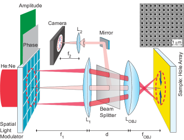
A diagram of the setup is given in Fig. 1. Based on SPP momentum conservation we designed the imaging system such that plasmons are launched toward the center. The light reflected from the sample is imaged on the detector. This light includes both the direct reflection of the illuminating beam and the scattered light from SPPs. Thus the resulting image is a combination of both the SLM amplitude pattern and the generated SPPs.
To separate plasmonic from optical effects we spatially design the amplitude of the incident light to define four bright plasmon launching areas and one central dark arena. Any intensity detected inside the arena is purely plasmonic. The designed amplitude profile for focusing experiments is a four-block pattern of fully “on” (A=1) superpixels on an “off” (A=0) background.
The resulting illuminated areas on a bare gold substrate are visible in Fig. 2a. The overall phase is constant. Each “on” block is 10 x 8 superpixels in size. Because no SPPs are launched on bare gold due to momentum mismatch, the image of Fig. 2a is used as a background reference and measure of contrast ratio between the “on” and “off” areas. The observed contrast is nearly three orders of magnitude confirming that no photons enter the SPP arena.
When the designed amplitude profile is projected onto the hole array, SPPs propagate into the central dark arena. The nanohole array has a dual role: it is used to launch SPPs (bright rectangles in Figs. 2b-2d) and to visualize the launched SPP’s through their out-of-plane scattering in the central arena. The SPPs are launched only along the direction of the incident polarization as seen in Figs. 2c and 2d, consistent with expectations van_oosten_nanohole_2010 . In Fig. 2b, the sample is illuminated both by the structured amplitude profile and an additional white light source, revealing both the hole array grating itself (the fast amplitude modulation) and the laser light. This figure also demonstrates the optical resolution of the setup: sufficient to resolve the presence of the hole array pattern but not the shape of holes.
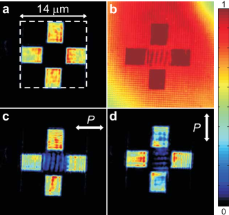
When two counterpropagating SPP waves interfere, a standing wave pattern of intensity is created. The observed period of the fringe pattern is clearly not half the SPP wavelength, as is expected for SPPs propagating on an ideally smooth and non-corrugated sample. The measured fringe period is m. We attribute the fringe patterns to a Moire effect between the true standing SPP wave and the periodicity of the arrays.
Now we present experiments of SPP focusing with digital phase control. The achieved SPP focusing is shown in Fig. 3. We use a phase optimization loop VellekoopOC2008 to focus SPPs at a pre-chosen target. This loop yields the optimal phase for each superpixel as well as the relative contribution to focus.The amplitude profile is the same as for the bare gold case with four launching areas and a central dark arena where only SPPs can propagate. The incident polarization is diagonal with the grating lines so as to have all available angles ( range) contributing to the focus, thereby maximizing the NA and resolution.
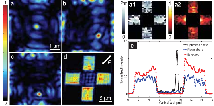
Successful focusing at center of the SPP arena is shown in Fig. 3a. The structured SPP wavefront produces an intensity in the designated target that is at least 20 times higher than the average SPP background of an unstructured wavefront. The measured size of the plasmonic focus is 420 nm, consistent with the diffraction limit of our optics. The flexibility of the method (scanning the focus) is demonstrated in Fig. 3b and Fig. 3c which show the SPP focus relocated without mechanical motion to controlled positions in the plasmonic arena. Thus the plasmonic arena is our field-of-view.
We interpret SPP focusing in terms of Green’s functions connecting the electric fields at any two points. We idealize every “on” superpixel with a light source positioned at and with phase and strength . The amplitude of the electric field (normalized to the incident field) at the target due to these sources is
| (2) |
where is the Green’s function connecting each source to the target, and the sum runs over all the “on” superpixels of the amplitude profile. The target field is maximal when all source contributions are in phase. The optimal phase for superpixel is . Imposing this phase to the superpixel yields an intensity increase of . We can write
| (3) |
Equation 3 implies that when a focus is achieved in the SPP arena, the recorded optimal phases and relative contributions of the superpixels give the Green’s function for a plasmonic source located at that exact focus point. Thus the superpixels of the SLM effectively behave as amplitude and phase sensitive detectors. These results are valid for any Green’s function or nanostructure and can be extended to the time domain FinkPRL and the transfer matrix approach popoff_measuringtransmission_2010 .
For a perfectly smooth sample with no corrugations the SPP Green’s function is simply a cylindrical wave in two dimensions (the Hankel function with the complex-valued SPP momentum). Our digitally measured Green’s function includes the light-to-SPP coupling and therefore presents much more complexity.
With digital plasmonics we demonstrate the first “black-box” with nanoscale SPP outputs and text file inputs. Specifically, we focus SPPs on hole arrays and locally scan the focus freely over a field-of-view (SPP arena) without any mechanical translation. In achieving such dynamic focusing we recorded amplitude and phase Green’s functions. These digital records, which contain the full complexity of the Green’s function, are used as self-calibrated inputs. The method can be extended to any plasmonic structure and to the time domain. This digital plasmonic workbench is anticipated to enable interdisciplinary applications in microscopy, optical data storage and in bio-sensing.
We thank Elbert van Putten and Jean Cesario for stimulating and helpful discussions. For sample fabrication we thank Hans Zeijlermaker. This work is part of the research program of the “Stichting voor Fundamenteel Onderzoek der Materie”, which is Financially supported by the “Nederlandse Organisatie voor Wetenschappelijk Onderzoek”.
References
- (1) Barnes, W. L., Dereux, A. & Ebbesen, T. W. Surface plasmon subwavelength optics. Nature 424, 6950, 824 (2003).
- (2) Ozbay, E. Plasmonics: Merging photonics and electronics at nanoscale dimensions. Science 311, 5758, 189 (2006).
- (3) Polman, A. APPLIED PHYSICS: plasmonics applied. Science 322, 5903, 868 (2008).
- (4) Schuller, J. A. et al. Plasmonics for extreme light concentration and manipulation. Nat Mater 9, 3, 193 (2010).
- (5) Prodan, E., Radloff, C., Halas, N. J. & Nordlander, P. A hybridization model for the plasmon response of complex nanostructures. Science 302, 5644, 419 (2003).
- (6) Atwater, H. A. & Polman, A. Plasmonics for improved photovoltaic devices. Nat Mater 9, 3, 205 (2010).
- (7) Altewischer, E., van Exter, M. P. & Woerdman, J. P. Plasmon-assisted transmission of entangled photons. Nature 418, 6895, 304 (2002).
- (8) Akimov, A. V. et al. Generation of single optical plasmons in metallic nanowires coupled to quantum dots. Nature 450, 7168, 402 (2007).
- (9) Ebbesen, T. W., Genet, C. & Bozhevolnyi, S. I. Surface-plasmon circuitry. Phys Today 61, 5, 44 (2008).
- (10) Engheta, N. Circuits with light at nanoscales: Optical nanocircuits inspired by metamaterials. Science 317, 5845, 1698 (2007).
- (11) Liu, N. et al. Plasmonic analogue of electromagnetically induced transparency at the drude damping limit. Nat Mater 8, 9, 758 (2009).
- (12) Ergin, T., Stenger, N., Brenner, P., Pendry, J. B. & Wegener, M. Three-Dimensional invisibility cloak at optical wavelengths. Science 328, 5976, 337 (2010).
- (13) Fang, N., Lee, H., Sun, C. & Zhang, X. Sub-Diffraction-Limited optical imaging with a silver superlens. Science 308, 5721, 534 (2005).
- (14) Vellekoop, I. M., van Putten, E. G., Lagendijk, A. & Mosk, A. P. Demixing light paths inside disordered metamaterials. Opt. Express 16, 1, 67 (2008).
- (15) Cizmar, T., Mazilu, M. & Dholakia, K. In situ wavefront correction and its application to micromanipulation. Nat Photon 4, 6, 388 (2010).
- (16) Dionne, J. A., Diest, K., Sweatlock, L. A. & Atwater, H. A. PlasMOStor: a Metal-Oxide-Si field effect plasmonic modulator. Nano Lett 9, 2, 897 (2009).
- (17) MacDonald, K. F., Samson, Z. L., Stockman, M. I. & Zheludev, N. I. Ultrafast active plasmonics. Nat Photon 3, 1, 55 (2009).
- (18) Utikal, T., Stockman, M. I., Heberle, A. P., Lippitz, M. & Giessen, H. All-Optical control of the ultrafast dynamics of a hybrid plasmonic system. Phys. Rev. Lett. 104, 11, 113903 (2010).
- (19) Durach, M., Rusina, A., Stockman, M. I. & Nelson, K. Toward full spatiotemporal control on the nanoscale. Nano Lett 7, 10, 3145 (2007).
- (20) Aeschlimann, M. et al. Adaptive subwavelength control of nano-optical fields. Nature 446, 7133, 301 (2007).
- (21) Li, X. & Stockman, M. I. Highly efficient spatiotemporal coherent control in nanoplasmonics on a nanometer-femtosecond scale by time reversal. Phys. Rev. B 77, 19, 195109 (2008).
- (22) Volpe, G., Cherukulappurath, S., Parramon, R. J., Molina-Terriza, G. & Quidant, R. Controlling the optical near field of nanoantennas with spatial Phase-Shaped beams. Nano Lett 9, 10, 3608 (2009).
- (23) Garcia-Vidal, F. J., Martin-Moreno, L., Ebbesen, T. W. & Kuipers, L. Light passing through subwavelength apertures. Rev. of Mod. Phys. 82, 1, 729 (2010).
- (24) Sentenac, A. & Chaumet, P. C. Subdiffraction light focusing on a grating substrate. Phys. Rev. Lett. 101, 1, 013901 (2008).
- (25) Johnson, P. B. & Christy, R. W. Optical constants of the noble metals. Phys. Rev. B 6, 12, 4370 (1972).
- (26) van Putten, E. G., Vellekoop, I. M. & Mosk, A. P. Spatial amplitude and phase modulation using commercial twisted nematic lcds. Appl. Opt. 47, 12, 2076 (2008).
- (27) van Oosten, D., Spasenovic, M. & Kuipers, L. Nanohole chains for directional and localized surface plasmon excitation. Nano Lett 10, 1, 286 (2010).
- (28) Vellekoop, I. & Mosk, A. Phase control algorithms for focusing light through turbid media. Opt. Commun. 281, 11, 3071 (2008).
- (29) Derode, A., Roux, P. & Fink, M. Robust acoustic time reversal with high-order multiple scattering. emphPhys. Rev. Lett. 75, 23, 4206 (1995).
- (30) Popoff, S. M. et al. Measuring the transmission matrix in optics: An approach to the study and control of light propagation in disordered media. Phys. Rev. Lett. 104, 10, 100601 (2010).