Breakdown of counterflow superfluidity in a disordered quantum Hall bilayer
Abstract
We present a theory for the regime of coherent interlayer tunneling in a disordered quantum Hall bilayer at total filling factor one, allowing for the effect of static vortices. We find that the system consists of domains of polarized superfluid phase. Injected currents introduce phase slips between the polarized domains which are pinned by disorder. We present a model of saturated tunneling domains that predicts a critical current for the breakdown of coherent tunneling that is extensive in the system size. This theory is supported by numerical results from a disordered phase model in two dimensions. We also discuss how our picture might be used to interpret experiments in the counterflow geometry and in two-terminal measurements.
I Introduction
In a quantum Hall bilayer at total Landau level filling , Coulomb interactions induce a state with interlayer phase coherence Murphy et al. (1994); Lay et al. (1994). This state is expected to be approximately the Halperin [111] state Halperin (1983), which can be understood as a Bose-Einstein condensate of interlayer excitons Fertig (1989); Eisenstein and MacDonald (2004). The motion of excitons corresponds to counterflowing electrical currents in the layers, so that excitonic supercurrents can give dissipationless electrical transport. The superfluid properties of the [111] state have been demonstrated theoretically by Wen and Zee Wen and Zee (1992, 2003).
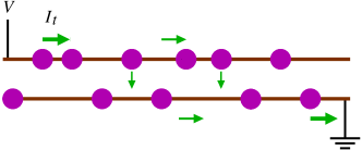
This counterflow superfluidity can be probed in tunneling experiments. In the tunneling geometry (Fig. 1), a current is injected into the top layer at one corner and removed from the bottom layer at the opposite corner. These current flows may be written as superpositions of layer-symmetric and layer-antisymmetric currents,
| (1) |
where the two components refer to currents in the two layers. Thus, the tunneling experiment corresponds to a flow of layer-symmetric current, with equal counterflow currents injected by both the electron source and drain. The symmetric component is transported by a dissipationless edge state, which does not penetrate the bulk due to an energy gap to charged excitations. However, the bulk can carry the counterflow component as a charge-neutral excitonic supercurrent. Since both these channels are dissipationless, we expect dissipationless electrical transport. In particular, a finite interlayer current at negligible interlayer voltage has been predicted Wen and Zee (1993); Ezawa and Iwazaki (1993). This has been recently confirmed by four-terminal measurements by Tiemann and coworkers Tiemann et al. (2008, 2009). This phenomenon can be regarded as a form of the Josephson effect Wen and Zee (2003). Note that thermally activated quasiparticles and contact effects Su and MacDonald (2010) can give rise to complications in actual experiments.
The Josephson-like regime persists for interlayer currents up to a critical value . Above , interlayer transport becomes dissipative. Nevertheless, interlayer coherence can still be detected in the interlayer characteristics of the system. A strong peak is observed at zero bias in the differential interlayer conductivity. This is followed at low bias by a regime with negative differential conductivity Spielman et al. (2000); Eisenstein (2003). This regime can be studied theoretically treating the interlayer tunneling as a perturbation Jack et al. (2004); Stern et al. (2001); Balents and Radzihovsky (2001).
In this paper, we focus on the Josephson regime below the critical current, and present a physical picture of its breakdown. We have previously presented, in a short paper Eastham et al. (2010), a theory of this breakdown based on numerical results on a one-dimensional model. The aim of the present paper is to present numerical results for a two-dimensional model, which directly demonstrate the breakdown mechanism in a realistic geometry. The key motivation of our work is to understand the observation Tiemann et al. (2009) that the critical current is proportional to the sample area. (Area scaling is also observed in the zero-bias peak of the interlayer conductivity Finck et al. (2008). We will discuss this in section VI.) The source and drain contacts for the applied current are located at opposite ends of the system. If one models this system as a clean homogeneous bilayer using reasonable estimates of the tunnel splitting, one finds that the injected current should have tunneled across the bilayer within a few microns of the source contact [ in Eq. (6)]. Such a current profile would suggest that the critical value of the interlayer current should not depend on the sample length in the direction of the current Fil and Shevchenko (2009); Abolfath et al. (2003); Su and MacDonald (2010). Put another way, the area scaling of the critical current could only be explained by a clean model of the bilayer if one accepts a tunnel splitting that is anomalously small by several orders of magnitude Su and MacDonald (2010).
A similar puzzle is found in the original observation of dissipationless counterflow Tutuc et al. (2004); Kellogg et al. (2004) in the counterflow geometry (Fig. 3). Again, counterflow currents apparently traverse the system over distances orders of magnitude further than expected. We will return to this geometry in the final section.
The resolution of this puzzle lies in the presence of disorder. We shall see (Fig. 2) that, in the presence of static phase disorder (pinned vortices), the supercurrent profile can be pinned by disorder. The time-independent supercurrents can then penetrate into the sample over indefinitely large distances, limited only by the finite size of the sample. In fact, we find that dissipation only appears when supercurrents completely fill the sample. This mechanism gives a critical current [Eq. (11)] which is proportional to the area of the sample. The magnitude of this critical current agrees with experiments, using reasonable estimates of the parameters Eastham et al. (2010).
This paper is organized as follows. We will discuss the origin of disorder in the bilayer in Section II. Then, in section III, we will introduce the phase Hamiltonian for the excitonic superfluid that describes the interlayer-coherent phase of the quantum Hall bilayer. In section IV, we discuss how quenched vortices in the superfluid affect the ground state of the system and its response to injected currents. Then, in section V, we present the results of a numerical simulation of the bilayer in the tunneling configuration to support the prediction of our theory. In the final section, we discuss how our picture can be used to interpret experiments for the bilayer in other configurations.
II Model of Disorder
Weak disorder, such as a spatially varying tunneling splitting, does not affect the tunneling properties of the system dramatically Ros and Lee (2010). A tunneling mechanism based on a disordered edge has been proposed by Rossi et al Rossi et al. (2005). However, such a theory predicted linear scaling with the sample length but not its area.
We consider here a bilayer with charge disorder in the bulk. One common source for this disorder is the electrostatic potential due to disordered dopant layers. We expect the incompressible quantum Hall phase to occupy only a fraction of the sample, with the remainder occupied by puddles of compressible electron liquid. Thus, the incompressible phase forms a network of channels separating puddles of size , the distance to the dopants. We suppose that the width of the channels is of the order of the magnetic length nm. This coherent network model was first studied in the context of the quantum Hall bilayer by Fertig and Murthy Fertig and Murthy (2005).
In a quantum Hall superfluid, excess charge nucleates vortices in the exciton superfluid Eastham et al. (2009); Fertig and Murthy (2005); Stern et al. (2001); Balents and Radzihovsky (2001); Fogler and Wilczek (2001). For a balanced bilayer with individual layer fillings these vortices are merons of charge . (In an unbalanced bilayer the charges are Roostaei et al. (2008) .) In previous work Eastham et al. (2009), we have studied how the vortex density is determined by a competition between the superfluid energy cost of the vortex and the charging energy of each puddle. We found that the bilayer can be strongly disordered in the current experimental regimes. This suggests that the random field due to the pinned vortices has an exponentially decaying correlation function in space.
The above scenario provides a specific physical model for quenched vortices with short-ranged correlations in the exciton superfluid. The theory we present below depends on the existence of trapped fractional charges to create these vortices but does not depend crucially on the details of the disorder distribution. Our results should be valid as long as the vortices are dense enough that their separation () is smaller than the clean tunneling length scale [Eq. (6)].
III Phase model
In the previous section, we have outlined a model of disorder which induced quenched vortices in a quantum Hall state. To describe this exciton superfluid with quenched vortices, we start with an effective Hamiltonian for the phase of the superfluid. We separate out the component, , of the phase field that is due to the quenched vortices. The remaining component, , would have no vorticity in the ground state but may acquire vorticity in the presence of injected currents and other external perturbations. It can be shown that the effective Hamiltonian can be written as a random field XY model:
| (2) |
which describes the low-energy phase fluctuations of a bilayer containing pinned vortices. This form is a simple extension of the form for a clean model Wen and Zee (1993). The first term describes the superfluid stiffness to phase twists while the second describes the interlayer tunneling. We will assume that the quenched phase field has a correlation length of .
In the Josephson regime, there is no quasiparticle flow at zero temperature. All currents are accounted for by superflow and coherent tunneling. The counterflow supercurrent density above the ground state, , and the interlayer tunneling current density, , are related to the phase field by:
| (3) |
A time-varying superfluid phase gives rise to an interlayer voltage difference via the Josephson relation
| (4) |
Therefore, a state with a finite interlayer current at zero interlayer voltage is time-independent, corresponding to a local minimum of the energy (2). The stationary equation is simply the continuity equation stating that the loss of counterflow current is accounted for by interlayer tunneling: . This can be written as
| (5) |
All states with zero interlayer voltage obey this equation. The dependence on the injected current arises as the boundary conditions at the source and drain specifying the injected counterflow component . In terms of the phase field, this is a boundary condition on .
We expect that the counterflow current injected at the boundary will decay into the sample because interlayer tunneling will recombine electrons and holes across the two layers, as depicted in Fig. 3. In the clean case (), one expects Fil and Shevchenko (2009); Bak (1982) the static solution to show all the injected counterflow current tunneling across the bilayer over a “Josephson length” of
| (6) |
This length scale is estimated to be of the order of a few microns using realistic parameters.
Since the phase angle is compact, this implies a maximum injected current density of . For higher injected currents, phase slips enter and propagate through the system. This gives rise to a time-varying phase and hence a non-zero interlayer voltage via the Josephson relation (4).
Note that this picture of current penetration into the clean system gives a penetration depth as a microscopic length scale independent of the injected current. We will see below that the disordered system behaves qualitatively differently — the current can penetrate into an indefinitely large area of the system. The reason is that injected phase slips are pinned by disorder and therefore a static solution to Eq. (5) can persist to higher injected currents. In the next section, we will discuss this picture of pinning.
IV Pinned superfluid
We will now review the heuristic theory of pinning presented in our previous work Eastham et al. (2010) in order to provide the context to interpret our simulation results. The quenched vortices play a crucial role for the critical current. They pin any injected supercurrents and sustain dissipationless states. This is reminiscent of how disorder pins magnetic flux in superconductors Tinkham (1996); Larkin and Ovchinnikov (1979); Vinokur and Koshelev (1990), or charge in charge-density waves Fukuyama and Lee (1978). However, we emphasize that there is a significant difference in the bilayer compared to these other systems. In the superconductor, the depinning force arises from the Lorentz force on the flux lines due to the bulk transport current. In charge-density-wave systems, depinning originates from the electric field in the bulk which is an insulator when the charge density cannot slide. In the quantum Hall bilayer, depinning arises from the injected charge current which is applied only at the sample boundary. Thus, in this case, the critical current will depend on how the depinning “forces” are transmitted through the system. In such a geometry, it is not immediately obvious how the critical current would scale with the area of the whole sample.
We will borrow from the Fukuyama-Lee theory Fukuyama and Lee (1978) of disordered charge density waves and the Imry-Ma theory Imry and Ma (1975) for ferromagnets in random fields. We recall the form of the ground states of the random field XY model, Eq. (2), in the weak disorder regime relevant for the bilayer. In this regime, it is energetically costly for the phase to follow the random field which varies over the scale of the correlation length . The ground state consists of domains of polarized phase. These domains cannot be arbitrarily large because the energy cost of the mismatch between the phase and random field grows with the domain size. The energy cost for a phase twist that varies over the scale is in dimensions. The typical tunneling energy of a polarized region of size is obtained by summing random energies in the range for its correlation areas, giving . The phases will twist when exceeds . Therefore, the ground state consists of domains of size determined by
| (7) |
This “Imry-Ma scale” for the domain is:
| (8) |
In this ground state of polarized domains, the average coarse-grained phase over a domain is chosen such that the tunneling energy of each domain is minimized. Since is the tunneling current at position , the total tunneling current over the domain vanishes.
In two dimensions, . We see that, in the experimentally relevant regime of , this new disorder-induced length scale is much larger than the Josephson length. This is the length scale controlling current penetration into the sample. However, as we see below, this should not be interpreted simply as a renormalized length scale for how far counterflow currents penetrate into the sample.
Consider now the effect of an injected counterflow which imposes a phase twist at the boundary. The phase will therefore twist away from its equilibrium configuration. We assume that the domain at the boundary remains polarized at short distances and so will rotate uniformly on the scale of . This generates a tunneling current which reduces the counterflow current. The residual counterflow currents will be transmitted further into the sample, causing the domains there to rotate in a similar way.
This picture allows us to average over each domain. The total tunneling current in a domain consists of a similar random sum to that for the tunneling energy, , and is given by where
| (9) |
is the deviation of the coarse-grained phase from its equilibrium value, and the range of is typically . To minimize the region pushed out of equilibrium by the injected current, each domain will rotate so as to minimize the counterflow current transmitted into the sample. This maximizes the tunneling current and is achieved if we choose . Thus, we argue that forcing at a boundary leads to a self-organized critical state, in which the driven part of the system is saturated at the threshold . This means that the area of the system driven out of equilibrium to provide coherent tunneling is simply proportional to the number of domains necessary to carry the injected current . Each domain can support a current of and so
| (10) |
The critical current is reached when all domains in the sample are saturated: for a 2D sample of area . Therefore the critical current for a sample of area is
| (11) |
This formula also applies to the 1D case with being the sample length.
V Numerical results
We will now present numerical results to support the theory in the previous section. Our numerical results are obtained using the dissipative model
| (12) |
whose stationary solutions are the local minima of Eq. (2). This is performed on a lattice model. The phase field at site is uncorrelated with the phase field at any other site. This corresponds to taking the lattice spacing to be the correlation length of the original continuum model. The natural unit of current is . The results that we present below are the results for a 20020 lattice, averaged over 500 realizations of the disorder. For this illustration, we take the ratio of the tunneling strength to the superfluid stiffness to be . This corresponds to a Josephson depth of the order of a lattice spacing and a domain size of 2 lattice spacings. Although this is not deep in the weak-disorder regime considered in the previous section, our results appear to support the conclusions in that section.
The boundary conditions for Eq. (2) are determined by the current flows through the sample Su and MacDonald (2010). We consider a tunneling geometry in which, as seen in Fig. 2, a current is injected into the top layer at the bottom left corner and removed from the bottom layer at the bottom right corner. As already discussed [Eq. (1)], the counterflow component of the currents corresponds to equal counterflow currents injected by both the electron source and drain.
The ground state of the system is found by evolving from a random state using the dissipative dynamics (12) with the boundary condition of no injected current. From Eq. (3), this corresponds to everywhere on the boundary with being the normal to the boundary. To model the current injection in a tunneling experiment, we then slowly increase the counterflow current at the source and drain sites (1 and 2) to the final values . For the low values of the injected current , the dynamics reach a static solution, corresponding to the Josephson regime with vanishing interlayer voltages. At higher currents, these time-independent solutions break down and the phase winds continuously in time. This corresponds to the breakdown of the d.c. Josephson regime and the appearance of a state with finite interlayer voltages.
We expect that the counterflow current injected at the boundary will decay into the sample because interlayer tunneling will recombine electrons and holes across the two layers. We find that the manner in which this occurs is qualitatively different in clean and disordered bilayers. As mentioned in section I, the penetration depth of the injected current is simply the Josephson length in the clean case. We see in Fig. 2 that, for the disordered case, current penetrates further and further into the sample as we increase the injected current from the two ends. We see from the border of the regions with finite tunneling () that the counterflow region increases linearly in area () with the injected current. This is consistent with the prediction [Eq. (10)] for as a function of the injected current from our theory.
At a high enough injected current (), the current profiles from the contacts (lower left and right corners) will meet in the middle of the lattice. Beyond this point, further increases in current cannot be accommodated by coherent tunneling and an interlayer voltage develops.
We emphasize that this interpretation of the threshold for the breakdown of the stationary solutions is qualitatively different from the clean case. In the clean model, the breakdown can be understood in terms of the injection of phase solitons at the boundary Littlewood and Rice (1982); Fil and Shevchenko (2009) when the injected current exceeds the superflow that can be supported by a static phase twist . These phase solitons propagate through the sample. Thus, the phase at any point varies in time, and the system develops an interlayer voltage by the a.c. Josephson effect. In this language, we can say that these injected solitons can be pinned by disorder so that stationary solutions exist even when there are many solitons in the system.
VI Discussion
We have so far focused our discussion on the bilayer in the tunneling geometry. Finally, we will discuss how two other experimental situations can be interpreted in our theory. The first setup is the transport in the bilayer in a counterflow geometry where the source and drain contacts are on the same side of the bilayer while the other end is short-circuited to allow the current to flow from the top layer to bottom without the need for tunneling. This is depicted schematically in Fig. 3. This was first investigated by Tutuc et al Tutuc et al. (2004) and Kellogg et al Kellogg et al. (2004). A large current ( in figure) was found passing through the short circuit that join the top and bottom layers. This seems to imply that there is no leakage by tunneling across hundreds of microns. As we discussed in section I for the case of the tunneling geometry, a realistic estimate of the tunneling rate based on a clean bilayer predicts that the injected current would have tunneled across the bilayer within a micron and no current should remain at the far end.
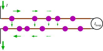
In our theory, this situation can be simulated by solving Eq. (12) with injected counterflow current at one end only, say the left end of Fig. 2. We expect the tunneling domains to saturate successively from this end, and the current profile is the same as that found in Fig. 2 for this side of the sample. There will be no current flow on the right side. In other words, we expect to see zero current in the short-circuit loop () in the Josephson regime. As we increase the injected current to , the current-carrying region reaches the other end of the sample. Any further currents will pass through the short circuit. For an ideal loop, we expect . However, the short circuit itself should have a finite resistance. Therefore, the presence of a non-zero implies a small interlayer voltage at the end of the sample. In the phase theory, the Josephson relation (4) means that the superfluid phase must wind in time. Thus, a static solution to Eq. (12) becomes impossible anywhere in the system and the whole sample develops an interlayer voltage. We expect that the phase dynamics will be complex and chaotic. The nature of the steady state would depend on details of the damping mechanisms. This provides a zero-temperature picture of the counterflow geometry and is consistent with the recent experiments of Yoon et al Yoon et al. (2010), in which the loop current is negligible for tunnel currents below a critical value. We should keep in mind that, at finite temperatures, there may be in-plane resistances associated with the flow of thermally activated quasiparticles.
The second situation we wish to discuss is the two-terminal measurements of zero-bias interlayer conductance, , by Finck et al. Finck et al. (2008) Within our theory, this could be interpreted as the dissipative regime (i.e. no static solutions for the phase) above the critical current. We note that these measurements were performed close to the phase boundary between the excitonic superfluid with interlayer coherence and the incoherent quantum Hall liquid. We expect the critical current to vanish near the phase boundary Tiemann et al. (2009); Eastham et al. (2010). Therefore, it is easy to exceed the critical current in this region of the phase diagram. Then, we see in Fig. 2 that a non-zero interlayer voltage develops across the whole sample and the tunneling current exists over the whole sample. In other words, should be proportional to the area of the sample, as seen by Finck et al. We point out that, whereas this interpretation gives an intrinsic zero-temperature source of a finite conductance, there may be other sources of dissipation. Even below there could be a finite dissipation due to contact resistances and thermal activated vortex motion. Fluctuations in the pinning energies could also lead to very weakly pinned regions in large samplesCoppersmith (1990), which may lead to dissipation below even at .
In summary, we have presented a theory of the Josephson regime of coherent tunneling in a disordered quantum Hall bilayer with static pinned vortices. We find that, in the tunneling geometry, there are two current-carrying regions emanating separately from the source and drain contacts. In these regions, coherent tunneling is saturated. All injected counterflow current is lost by tunneling at the edge of these regions. The area of the saturated region grows linearly with the injected current . This linear relation is predicted by our theory and is confirmed by the numerical results presented here. This is analogous to the Bean critical state for flux penetration into a disordered superconductor.
This picture tells us that the system reaches the critical current when the whole sample is saturated with coherent tunneling. This results in a critical current that is extensive for sufficiently large samples that contain many domains of polarized phase. In contrast, the clean limit Su and MacDonald (2010) sees area scaling for only for small samples (small compared to the Josephson length).
Theoretically, our results are qualitatively different from clean theories Su and MacDonald (2010) because of the existence of these pinned polarized domains. The size of these domains is a disordered-induced length scale that emerges in our theory [Eq. (8)]. This scale has no counterpart in the clean system. It would be therefore be useful if this length scale can be probed in experiments. We note that, for the area-scaling formula (11) to apply, the sample should be large enough to include many complete domains. For sample dimensions smaller than , the system should cross over to a regime where scales with the square-root of the sample dimension Eastham et al. (2010):
| (13) | |||||
| (14) |
This crossover provides an experimental probe of the domain size .
We thank P. B. Littlewood for helpful discussions. This work was supported by EPSRC-GB (EP/C546814/01) and Science Foundation Ireland (SFI/09/SIRG/I1952).
References
- Murphy et al. (1994) S. Q. Murphy, J. P. Eisenstein, G. S. Boebinger, L. N. Pfeiffer, and K. W. West, Phys. Rev. Lett. 72, 728 (1994).
- Lay et al. (1994) T. S. Lay, Y. W. Suen, H. C. Manoharan, X. Ying, M. B. Santos, and M. Shayegan, Phys. Rev. B 50, 17725 (1994).
- Halperin (1983) B. I. Halperin, Helv. Phys. Acta 56, 75 (1983).
- Fertig (1989) H. A. Fertig, Phys. Rev. B 40, 1087 (1989).
- Eisenstein and MacDonald (2004) J. P. Eisenstein and A. H. MacDonald, Nature 432, 691 (2004).
- Wen and Zee (1992) X. G. Wen and A. Zee, Phys. Rev. Lett. 69, 1811 (1992).
- Wen and Zee (2003) X. G. Wen and A. Zee, Int. J. Mod. Phys. B 17, 4435 (2003).
- Wen and Zee (1993) X. G. Wen and A. Zee, Phys. Rev. B 47, 2265 (1993).
- Ezawa and Iwazaki (1993) Z. F. Ezawa and A. Iwazaki, Phys. Rev. B 48, 15189 (1993).
- Tiemann et al. (2008) L. Tiemann, W. Dietsche, M. Hauser, and K. von Klitzing, New J. Phys. 10, 045018 (2008).
- Tiemann et al. (2009) L. Tiemann, Y. Yoon, W. Dietsche, K. von Klitzing, and W. Wegscheider, Phys. Rev. B 80, 165120 (2009).
- Su and MacDonald (2010) J.-J. Su and A. H. MacDonald, Phys. Rev. B 81, 184523 (2010).
- Spielman et al. (2000) I. B. Spielman, J. P. Eisenstein, L. N. Pfeiffer, and K. W. West, Phys. Rev. Lett. 84, 5808 (2000).
- Eisenstein (2003) J. P. Eisenstein, Solid State Commun. 127, 123 (2003).
- Jack et al. (2004) R. L. Jack, D. K. K. Lee, and N. R. Cooper, Phys. Rev. Lett. 93, 126803 (2004).
- Stern et al. (2001) A. Stern, S. M. Girvin, A. H. MacDonald, and N. Ma, Phys. Rev. Lett. 86, 1829 (2001).
- Balents and Radzihovsky (2001) L. Balents and L. Radzihovsky, Phys. Rev. Lett. 86, 1825 (2001).
- Eastham et al. (2010) P. R. Eastham, N. R. Cooper, and D. K. K. Lee, arXiv:1003.5191 (2010).
- Finck et al. (2008) A. D. K. Finck, A. R. Champagne, J. P. Eisenstein, L. N. Pfeiffer, and K. W. West, Phys. Rev. B 78, 075302 (2008).
- Fil and Shevchenko (2009) D. V. Fil and S. I. Shevchenko, J. Phys.: Condens. Matter 21, 215701 (2009).
- Abolfath et al. (2003) M. Abolfath, A. H. MacDonald, and L. Radzihovsky, Phys. Rev. B 68, 155318 (2003).
- Tutuc et al. (2004) E. Tutuc, M. Shayegan, and D. A. Huse, Phys. Rev. Lett. 93, 036802 (2004).
- Kellogg et al. (2004) M. Kellogg, J. P. Eisenstein, L. N. Pfeiffer, and K. W. West, Phys. Rev. Lett. 93, 036801 (2004).
- Ros and Lee (2010) O. G. C. Ros and D. K. K. Lee, Phys. Rev. B 81, 075115 (2010).
- Rossi et al. (2005) E. Rossi, A. S. Nunez, and A. H. MacDonald, Phys. Rev. Lett. 95, 266804 (2005).
- Fertig and Murthy (2005) H. A. Fertig and G. Murthy, Phys. Rev. Lett. 95, 156802 (2005).
- Eastham et al. (2009) P. R. Eastham, N. R. Cooper, and D. K. K. Lee, Phys. Rev. B 80, 045302 (2009).
- Fogler and Wilczek (2001) M. M. Fogler and F. Wilczek, Phys. Rev. Lett. 86, 1833 (2001).
- Roostaei et al. (2008) B. Roostaei, K. J. Mullen, H. A. Fertig, and S. H. Simon, Phys. Rev. Lett. 101, 046804 (2008).
- Bak (1982) P. Bak, Rep. Prog. Phys. 45, 587 (1982).
- Tinkham (1996) M. Tinkham, Introduction to superconductivity (McGraw-Hill, Inc., New York, 1996).
- Larkin and Ovchinnikov (1979) A. I. Larkin and Y. N. Ovchinnikov, J. Low. Temp. Phys. 34, 409 (1979).
- Vinokur and Koshelev (1990) V. M. Vinokur and A. E. Koshelev, Sov. Phys. JETP 70, 547 (1990).
- Fukuyama and Lee (1978) H. Fukuyama and P. A. Lee, Phys. Rev. B 17, 535 (1978).
- Imry and Ma (1975) Y. Imry and S. Ma, Phys. Rev. Lett. 35, 1399 (1975).
- Littlewood and Rice (1982) P. B. Littlewood and T. M. Rice, Phys. Rev. Lett. 48, 44 (1982).
- Yoon et al. (2010) Y. Yoon, L. Tiemann, S. Schmult, W. Dietsche, K. von Klitzing, and W. Wegscheider, Phys. Rev. Lett. 104, 116802 (2010).
- Coppersmith (1990) S. N. Coppersmith, Phys. Rev. Lett. 65, 1044 (1990).